Warco WM250

Advert

Warco WM250

Viewing 25 posts - 1 through 25 (of 245 total)
  • Author
    Posts
  • #32886
    Dusty
    Participant
      @dusty

      Lathe has just died

      Advert
      #280409
      Dusty
      Participant
        @dusty

        I had been using my Warco this afternoon for about 40 minutes. I had stopped the lathe to change tools, pressed the start button, nothing, deader than a whole lot of dead things. Now I know nothing about electrickery. I am sure that one of you clever electrickery bods can point me in the right direction to effect a repair.

        Good job I have a recently acquired Myford so I could complete the job.

        #280414
        John Rudd
        Participant
          @johnrudd16576

          Ok, going to have to do this the hard way…

          Is the nvr switch latched on?

          Chuck guard in place? can you check the plug fuse?


          Edited By John Rudd on 26/01/2017 20:13:34

          #280417
          JasonB
          Moderator
            @jasonb

            The only time my 280 failed to start was when the speed control pot on the front went. Try it at full speed as when they go they act more like a switch – all or nothing.

            Suppose we should also ask if it is a DC or newer AC motor version.

            #280418
            John Stevenson 1
            Participant
              @johnstevenson1

              Fuse in a holder either on the rear of the machine or front panel, one of the unscrew with a thumb nail type.

              Does it have a separate E-Stop switch or rely on the No-volt switch ? If it has an E-stop check it hasn't been pressed by accident. [ Don't ask ] wink

              10A if I remember right.

              Again as John R has said, chuck guard? guard covering the change gears on the end ?

              #280498
              Dusty
              Participant
                @dusty

                Thanks Guys, plenty of things to try later on my return from taking you know who shopping, bah. having a brother who was an electrician has not helped but unfortunately I am no longer able to call on his assistance.

                #280555
                Dusty
                Participant
                  @dusty

                  Well I have checked all those things suggested and all appear O.K. except the switch does not latch on. I replaced the fuse in the plug with a brand new one but still no life. Is this the switch is defective or something more. For your information the lathe is about 8yrs old so is fitted with a DC motor and is as original. The micro switches on the chuck guard and gear cover are disabled and have been since new without problems. Where do I go to from here?

                  #280570
                  John Rudd
                  Participant
                    @johnrudd16576

                    Dusty,

                    Does the lathe run when you press the Green button on the nvr switch even tho' it doesnt latch?

                    If the motor runs, then it suggests a fault with either wiring associated with the latch part of the nvr sw or the nvr switch is defective( coil….)

                    Report back your findings and we will continue…

                    #280584
                    Les Jones 1
                    Participant
                      @lesjones1

                      Hi John,
                      I could not find a wiring diagram for the WM250 but I have found this one for the WM180 which I would think would be similar. I don't think you can go any further until Dusty answers your question.

                      Les.

                      #280586
                      Dusty
                      Participant
                        @dusty

                        No the lathe does not run at all. it makes the DoDo look healthy.

                        #280591
                        John Rudd
                        Participant
                          @johnrudd16576

                          Dusty,

                          Do you have a multimeter/know how to use one?

                          If you have/can use one, then with it switched to ohms( resistance) with one lead clipped to the Live pin of the plug ( unplug it from the mains first!) can you trace the wiring from there through to the speed control board, where there will be a wire attached to one of the Line connectors….so with the other meter probe connected to the Line connection…does the meter read approx 0.2 ohms?

                          then repeat with Neutral pin thru to the other Line connector on the speed controller….and report back your findings please….

                          #280623
                          Dusty
                          Participant
                            @dusty

                            Oh dear, I started to use my head for thinking rather than somewhere to put my hat. I came to the conclusion that power was not getting to the switch. I replaced the fuse in the back of the lathe lo and behold life, but oh dear a horrible clunking rattle noise a bit like gears not engaged properly. Speed was poor, so I used the speed control , made no difference, no change in speed still the horrid noise, that's when the board tripped out on the lathe circuit. I suspect it is the motor that is causing the noise, but is that through problems with the motor or problems with the electronics?

                            Edited By Dusty on 27/01/2017 17:14:57

                            #280627
                            John Rudd
                            Participant
                              @johnrudd16576

                              If you suspect that the board may be the cause, disconnect the motor from the lathe.

                              Follow the wires from the motor to where they are terminate, I suspect a fwd-o-rev switch?

                              Then connect a household 60watt lamp, mounted in a bulb holder with a length of cable attached…..connect to the terminals where the motor was wired to.

                              Now, go through the start procedure you use to run up the machine, but with the speed pot at minimum. Then increase the speed pot and observe if the lamp increases in brightness as you turn the pot……if the lamp glows dimly or is at max brightness, there is an issue with the control board……

                              If the above shows that speed controller appears fine, you will need to remove the motor for further checks.

                              NOTE…..if you remove any wiring, ensure you mark it to ensure it goes back from whence it came……

                              #280629
                              Dusty
                              Participant
                                @dusty

                                John, silly question will that work with a D.C. control circuit, as I said I know next to nothing about electrikery.

                                #280630
                                Richard Marks
                                Participant
                                  @richardmarks80868

                                  Check for sticky brushes and carbon deposits in the motor causing tracking, common fault on these motors.

                                  #280634
                                  John Rudd
                                  Participant
                                    @johnrudd16576

                                    The light bulb doesnt care what the supply to it is….AC or DC…..

                                    Edited By John Rudd on 27/01/2017 17:44:28

                                    #280641
                                    SteveW
                                    Participant
                                      @stevew54046

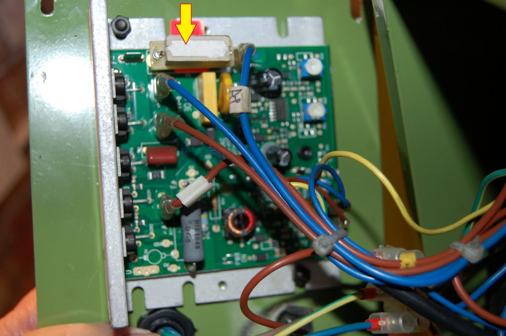
                                      Check out earlier threads. When mine died it was just this resistor. Not pressed fully home. I checked motor with 12v charger.board.jpg

                                      #280841
                                      Dusty
                                      Participant
                                        @dusty

                                        Well some sort of success it appears the speed control is working O.K. I got the result that John described, the only thing was the NVR needed holding in and started buzzing whilst doing the test.

                                        #280950
                                        John Rudd
                                        Participant
                                          @johnrudd16576

                                          Dusty,

                                          Do you have a dvm/ multimeter and know how to use it?

                                          If so, you need to trace the wiring to the coil side of the nvr switch…..

                                          The wiring associated with the interlocks that were removed is intact?

                                          Before condemning the switch, its easier to verify whats going in with it first…

                                          #280954
                                          Les Jones 1
                                          Participant
                                            @lesjones1

                                            It is possible that the interlock switches (Chuck guard, change wheel cover and any emergency stop switches) are wired in series with the coil on the NVR switch. This would mean that the motor would run while the start button was pressed when the interlock circuit was broken but the NVR switch would not latch in. This is the way my Chester DB10G was originaly wired.

                                            Les.

                                            #280962
                                            Dusty
                                            Participant
                                              @dusty

                                              The interlocks first. When I purchased the lathe the micro switch on the change wheel guard was broken (physically} I was sent a new one and this was fitted by someone local who Warco had arranged. He fitted it but bypassed it as he said it is likely to be a source of problems. The chuck guard micro switch is as fitted but the chuck guard is removed leaving it permanently closed. No other switches in circuit. I have acquired a multimeter but have no experience of using it. I have now located the operators manual and lo and behold in it is a wiring diagram.

                                              Edited By Dusty on 29/01/2017 09:50:37

                                              #280999
                                              John Rudd
                                              Participant
                                                @johnrudd16576

                                                If you can scan the wiring diagram, we can advise ( Les, myself, anyone else with a bit of knowledge of elektrikery) how best to proceed……

                                                #281281
                                                Dusty
                                                Participant
                                                  @dusty

                                                  Having scanned the wiring diagram it has dawned on me that I do not know how to get it into a post, never having needed to before. I know that it can be done from an album but as the only way to upload to an album is by JPEG format, it does not help me. This is a learning curve I did not anticipate..

                                                  #281285
                                                  Nick_G
                                                  Participant
                                                    @nick_g
                                                    Posted by Dusty on 30/01/2017 16:33:45:

                                                    I know that it can be done from an album but as the only way to upload to an album is by JPEG format,

                                                    .

                                                    If you upload it to an album somebody here will post it into the forum for you. yes

                                                    Nick

                                                    #281286
                                                    John Rudd
                                                    Participant
                                                      @johnrudd16576

                                                      Dusty,

                                                      Send me a private message with your email address, I'll email you back with mine, then you can send me the scanned drawing.

                                                      I'll take a look and advise you on what to check…..unless you have an alternative…

                                                    Viewing 25 posts - 1 through 25 (of 245 total)
                                                    • Please log in to reply to this topic. Registering is free and easy using the links on the menu at the top of this page.

                                                    Advert

                                                    Latest Replies

                                                    Viewing 25 topics - 1 through 25 (of 25 total)
                                                    Viewing 25 topics - 1 through 25 (of 25 total)

                                                    View full reply list.

                                                    Advert

                                                    Newsletter Sign-up