Smart & Brown Model A

Advert

Smart & Brown Model A

Home Forums Workshop Tools and Tooling Smart & Brown Model A

Viewing 16 posts - 1 through 16 (of 16 total)
  • Author
    Posts
  • #409599
    Andrew Evans
    Participant
      @andrewevans67134

      Hello

      Does anyone on here own a Smart and Brown Model A toolroom lathe? What are your thoughts on it for the home workshop? Apart from the lathes.co.uk site there isn't much information out there.

      My current lathe is a Denford Viceroy 280 – I would like a machine that is a pleasure to use but I am not sure if a Model A would just feel very outdated. I have seen a number of people saying they love their S&B 1024 lathes – is a Model A going to give a similar experience?

      Andy

      Advert
      #19346
      Andrew Evans
      Participant
        @andrewevans67134
        #409606
        Lathejack
        Participant
          @lathejack

          I own a Model A that I've had for years, a great machine. Being a toolroom lathe it is built like a tank and is rock solid.

          I think mine is 1957 vintage, and shows no signs of wear at all. It is 4 1/2 inches centre hight but will swing about 9 1/2 inches. The width of the bed at 9 1/2 inches is more than twice the centre hight. When the crosslide is wound back far enough to machine at the maximum swing the cutting tool is still sat within the width of the bed, not overhanging the edge of the bed, so it cuts beautifully without trying to flex the saddle or twist the bed. So they are really nice machines to use if they are not badly worn.

          The cabinet is made from cast iron which also adds to the rigidity of the lathe. If the capacity of 9 inch swing by I think 20 between centres is enough then they are great for the home workshop, but being a proper toolroom lathe they are a bit heavier and little larger than some general purpose workshop lathes of the same capacity.

          #409631
          Clive Foster
          Participant
            @clivefoster55965

            Agree with Lathejack about the rock solidity, durability and high quality of the S&B Model A. If looking to buy one definitely go for a Mk 2 unless the price is very right on a Mk 1. Although the difference is, as Lathes.co.uk says, pretty much just a matter of tidying up details the end result is a far nicer machine to use.

            Objectively the major disadvantages of the S&B A are the screwfitting spindle nose and small spindle bore. I'd also find it an irritating faff to change the belt over for high / low range speed shifting. Although, to be fair most jobs will be either high range or low range ones so in practice the belt won't need shifting as often as might be expected. Before buying one do verify that the belt is in good order as a replacement needs to be joined in situ. Not massively difficult but its one of those jobs that most folk need to do a couple or three times before you get the technique nailed down. Irritating on a job you will only do once.

            VFD drive would get round the belt swopping business but the motor will almost certainly be hard wired 440 volts (220-380 was an option but rare in the UK) so its either get inside to alter the connections or fit a new motor. The S&B DNA demands heavy motor mount assemblies with very little access room. Pulling the motor for mods ready for VFD fitting will be a serious work out.

            If properly lubricated and in good order the spindle bearings pretty much "last for ever". Which is good as you seriously do not want to faff about getting adjustment right or (quadruple eek!) pull the spindle.

            The standard threads list is a little limited by some standards but the 27 provided should handle most things. It should have the excellent ball bearing intermediate gear assembly in the end gear train. Conversion between imperial and metric thread is generally easier than with many lathes beacuse the 127 conversion gear goes on the gearbox input shaft so a compound gear is not required for almost all metric pitches below 2 mm. Coarser than 2 mm needs a compound gear.  Pretty sure fitting a compound gear involves removing the banjo to change the stud assembly to take plain bore gears, as per the 1024 in standard form, which is a PIA.  I believe the gear specifications are the same as my 1024 so if you need more most can be got off the shelf from folk like HPC. Considerably cheaper than the usual hunt for factory specials.

            Its heavy. Around 1,300 lb, just over half a ton, bare.

            Bottom line is its a seriously good machine but I have to say that, were I in that market, I'd keep looking for a decent 1024 VSL which isn't much bigger overall but has usefully larger capacity. But I'm biased 'cos thats what I did with no regrets once we'd sweated, strained and cursed it into place. Twice the weight of the A!

            I have a PDF version of the manual. PM me if you'd like to see it. But frankly there is very little of great import inside.

            Clive

            Edited By Clive Foster on 17/05/2019 13:31:20

            Edited By Clive Foster on 17/05/2019 13:41:58

            #409643
            Andrew Evans
            Participant
              @andrewevans67134

              Thanks Lathejack and Clive, i appreciate the advice and the offer of the manual PDF. The one I had my eye on is on eBay and is a Mk.1 – looks good condition though. What are the main differences between the Mk.1 and Mk.2 besides the shape of the base?

              In terms of weight of this or a 1024 – I can move my Denford around with a pinch bar on my own, albeit its inch by inch – are these movable once they are in place without a big faff? Is there any space under the base to get a toe jack in for example so it can go onto pipes?

              Andy

              #409644
              Stueeee
              Participant
                @stueeee

                Some of the early mk 1s had a different arrangement for engaging the back gear. The power feed selector on the saddle is different too on the mk 1. More detail here: weblink

                Either version in reasonable condition will be a rigid accurate machine.

                #409652
                Norman Barber
                Participant
                  @normanbarber28134

                  I have owned a Mk2 B&S Model A for over twenty years and cannot speak too highly of it. If you are buying one make sure that it has a comprehensive range of collets – they are not easy to find second hand if any are missing. My only criticism of the machine is the flat belt drive which (for my machine) is a limiting factor for metal removal rate.

                  Norman

                  #409681
                  Lathejack
                  Participant
                    @lathejack

                    S&B produced some MK 2 Model A lathes built onto the MK1 cast iron cabinate, which is what my machine is. The later MK2 cabinate has all the controls mounted higher up, so you don't have to keep stooping down to adjust anything.

                    The old flat belt to the spindle on my Model A hasn't given any trouble, it is smooth and quiet. The reason a flat belt was used by S&B was to give a smooth drive from the motor and gearbox mounted in the bottom of the cabinet, without transmitting any vibration to the headstock spindle. That, along with the adjustable plain spindle bearings should give a fine finish on the workpiece.

                    #409701
                    Clive Foster
                    Participant
                      @clivefoster55965

                      Andrew

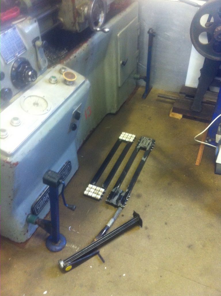
                      When it comes to moving machines both the Model A and 1024 can be shifted on pipe rollers or, often better, by sliding along steel rods laid rail fashion. Rail fashion rods tend to work much easier on a not quite flat concrete floor especially so if the final tamping has left slight ridges. If you have a really good surface such as proper floor coating / "paint", old fashioned metal loaded lino type "stuff' or the waterproof chipboard underflooring sheets that I have shallow roller devices work well. Basically up-engineered versions of the cheap ones sold for home owners moving cookers and other white goods.

                      The picture shows what I use with the 1024. Not sure how relevant the details will be to a Model A but it may spark some ideas. The roller frames were welded up from 1" square tubing off-cuts from the speed-frame system. Roller heads are about 4" square. The parts carrying the rollers were converted to U shape by milling off one side. Rollers are 1" nominal diameter nylon just under 1/2" wide so two fit inside each section of speed frame with thin separator collars about 1/2" diameter to reduce rubbing friction. Axles are 1/4" steel rod. Because the axle span inside the speed frame U sections is short the load capacity is "considerable". Lots of small rollers means the device can turn large radii without too much scuffing. Complex manoeuvres require a good deal of lifting and repositioning under the machine tho'.

                      The 1025 has 4 holes to take lifting rods. Old style 1" bore, thick wall, steel water pipe fits nicely. I modified some car jacks to fit securely in the pipes for easy lifting. Rover SD1 jack in the back corner permanently attached with the handle replaced by a welded on nut. Being tall it can be reached over the top of the lathe without serious contortions. Ford Capri one slides in on front tailstock end, Lancia HPE one at front headstock end and, I think, Citroen or Renault one fits in the back. Not sure about the last one as it was scavenged from a friends throw away pile.

                      lathe lift ga.jpg

                      1024 feet are shallow so a normal toe jack won't go under. I have used a click-click climb up then pole type farm jack in the aperture provided at the headstock end to get at the electrical relays after removing the door but this was less than stable. Done once only to slide 1/2" steel rod rails under and subsequently to remove them.

                      Hope this helps.

                      Clive

                      Edited By Clive Foster on 17/05/2019 21:12:13

                      #409709
                      Andrew Evans
                      Participant
                        @andrewevans67134

                        Thanks Clive, that is really useful. Andy

                        #409719
                        Hopper
                        Participant
                          @hopper

                          Posted by Lathejack on 17/05/2019 10:47:37:

                          It is 4 1/2 inches centre hight but will swing about 9 1/2 inches. The width of the bed at 9 1/2 inches is more than twice the centre hight. When the crosslide is wound back far enough to machine at the maximum swing the cutting tool is still sat within the width of the bed, not overhanging the edge of the bed, so it cuts beautifully without trying to flex the saddle or twist the bed.

                          Sign of a proper toolroom lathe.

                          #505033
                          jon edwards
                          Participant
                            @jonedwards85320

                            hello.

                            i have a type A smart and brown rescued from a pigeon infested barn….

                            i wonder if anyone has a manual showing how to correctly adjust the belt on the motor to the gearbox. mine is just not driving…

                            many thanks in advance

                            jon

                            #505140
                            old mart
                            Participant
                              @oldmart

                              We have a Mk 1.5 at the museum, it has the older type of backgear mechanism which I have improved. If you have a choice, get a Mk 2 with the totally revised and improved backgear. You can tell the difference at a glance, as the three speed gearbox control in the Mk 1 is in the middle and at the right hand side in the Mk 2. Another vital check before buying is to lift the belt lid and remove the cover to the right of the pulleys. The bronze gear must have a reasonable ammount of tooth depth on it. These are as rare as hens teeth, I have only seen one for sale ever.

                              The 1024 would be a better choice being slightly bigger as long as the spindle bearings are ok.

                              Do look at the "lathes UK" website before deciding. Remember the lathe weighs 3/4 of a ton.


                              Edited By old mart on 03/11/2020 15:11:50

                              #505153
                              Clive Foster
                              Participant
                                @clivefoster55965

                                Probably need to slacken off the main drive belt first so the gearbox can move to adjust the primary drive belt tension.

                                From the pictures I have it looks as if the main, flat belt drive, tension lever pivots off the gearbox so tightening the primary belt also tightens the main belt.

                                Going into more detail.

                                I have a pdf with two manuals and some supplementary "stuff" covering the Model A. I think the manuals are for the Mk 1.5 and Mk 2 versions.

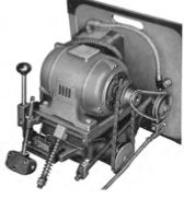
                                No explicit details on adjusting the motor to gearbox belt but there are a couple of pictures of the complete assembly removed from the machine. It appears that the motor sits on a platform with the gearbox hung beneath it on a pin. The picture shows a screwed rod with two nuts and a compression spring hanging in the wind close to a lug on the gearbox. I surmise that this arrangement allows the gearbox to be pivoted in a controlled manner to adjust the drive belt tension by rotating the nuts.

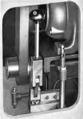
                                However the second, flat, drive belt tension lever is hung off the gearbox with a separate adjusting nut labeled A on another picture. The manual states that nut A is used to adjust the main drive belt tension.

                                Looks to me that the procedure for gearbox drive belt adjustment is to first loosen off the flat belt drive adjuster so there is slack in the system so the gearbox can safely be moved. Then adjust the gearbox drive belt before resetting the flat belt drive tension so that the release lever works correctly.

                                PM me your E-Mail address and I can send the pdf over.

                                Clive

                                #505178
                                Clive Foster
                                Participant
                                  @clivefoster55965

                                  Hi Jon

                                  Had another look at those manuals and figured out how to get a picture up.

                                  I'm now sure that the main belt tension lever lifts the gearbox up against the spring on the screw hanging in the wind in the picture below. Its proper place is probably in the lug with a U shape cut out behind it.

                                  drive unit.jpg

                                  So if there is slack in the main drive belt releasing the locked pair of nuts and screwing them down the rod will let the motor fall under the influence of gravity and the spring so tensioning the gearbox drive belt.

                                  Then you need to re-adjust the main drive belt as it will surely now be too tight. Picture and text from the manual.

                                  main belt adjustment.jpg

                                  Screw A adjusts the belt tension set by lever B.

                                  I presume you can get at things through the door on the front. The panel carrying the motor and all the gubbins hangs on the back of the cabinet. It will all be very heavy if you attempt to remove it.

                                  Clive

                                  #505187
                                  old mart
                                  Participant
                                    @oldmart

                                    The adjustment of the belts is one of the most frustrating and non intuative parts of the design. I did know how, but have forgotten and would have to learn it all over. The primary belt on the museum's machine is one of the linked types. It ran out of adjustment some years ago and Mike managed to extract it through the aperture where the speed control is screwed on. This was on the MK 1 and Mk 1.5 central control which is in line with the motor. The Mk 2 must have a remote linkage, so reaching the belt could be even more difficult. Mike removed one link and it has been ok ever since, I bought a metre of 13mm link belt just in case but it has not been needed yet.I have just got hold of a complete Norton gearbox and both leadscrew and feedscrew for the model A The casing is cracked, but could be repaired and nobody wanted it on ebay, so I got the lot for £45 including postage for 37 Kg of old iron.

                                    Edited By old mart on 03/11/2020 19:36:25

                                  Viewing 16 posts - 1 through 16 (of 16 total)
                                  • Please log in to reply to this topic. Registering is free and easy using the links on the menu at the top of this page.

                                  Advert

                                  Latest Replies

                                  Viewing 25 topics - 1 through 25 (of 25 total)
                                  Viewing 25 topics - 1 through 25 (of 25 total)

                                  View full reply list.

                                  Advert

                                  Newsletter Sign-up