A Fabricated Small DIY Tool & Cutter Grinder – Joe in Swakopmund

Advert

A Fabricated Small DIY Tool & Cutter Grinder – Joe in Swakopmund

Home Forums Workshop Tools and Tooling A Fabricated Small DIY Tool & Cutter Grinder – Joe in Swakopmund

Viewing 21 posts - 1 through 21 (of 21 total)
  • Author
    Posts
  • #18285
    Joseph Noci 1
    Participant
      @josephnoci1

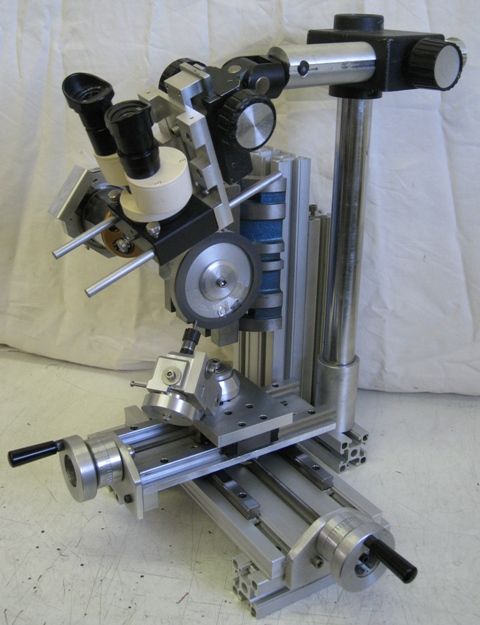
      A Basic Small T&C grinder, chiefly to sharpen small carbide drills and engraving D Bits.

      Advert
      #268637
      Joseph Noci 1
      Participant
        @josephnoci1

        Since I was asked to tell more about this small grinder, Here goes:

        mini grinder right view.jpg

        Post Character Count requires extreme brevity….

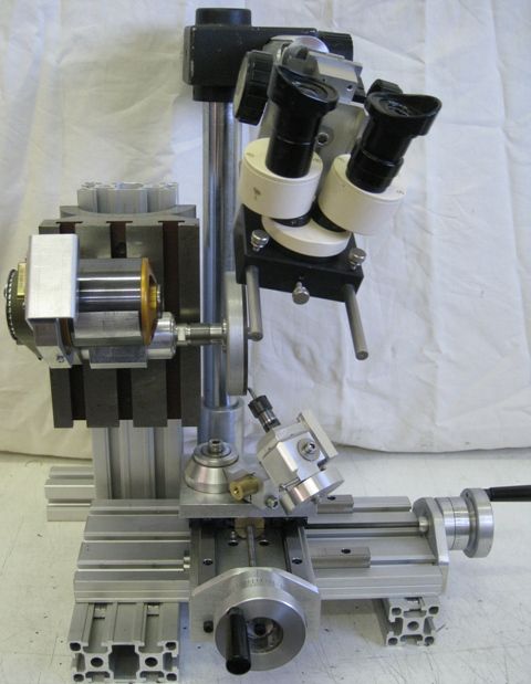
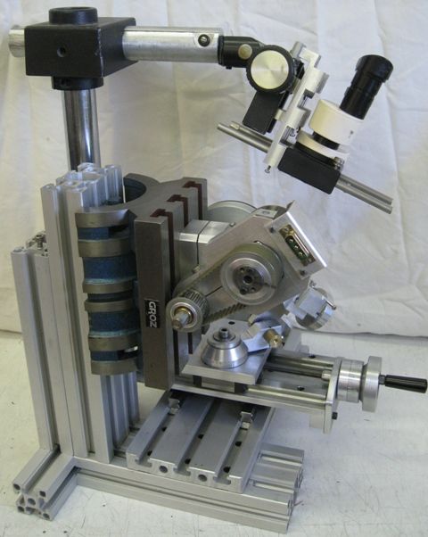
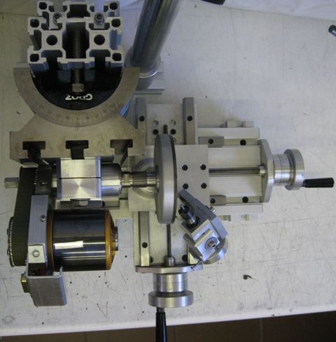
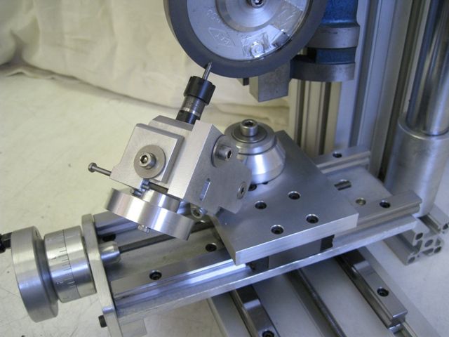
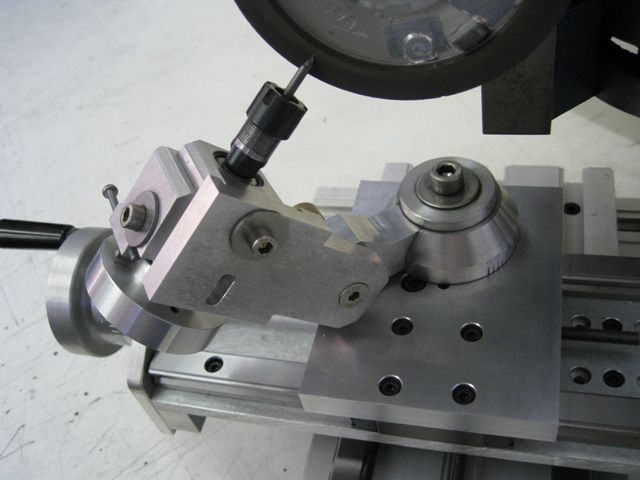
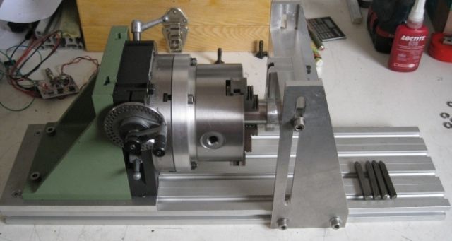
        A small grinder to sharpen small Carbide drill bits and V -D-engraving bits. (See a little in my 'new-member' intro).

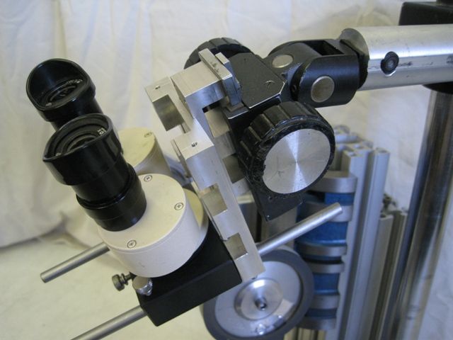
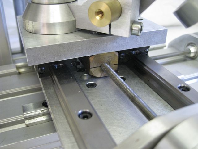
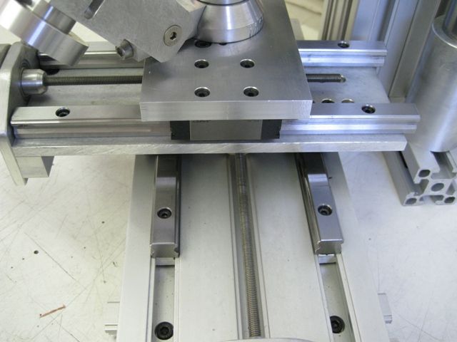
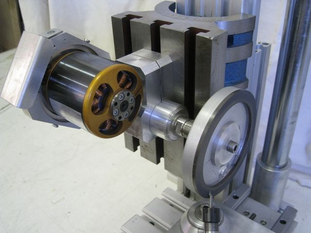
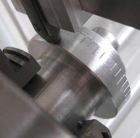
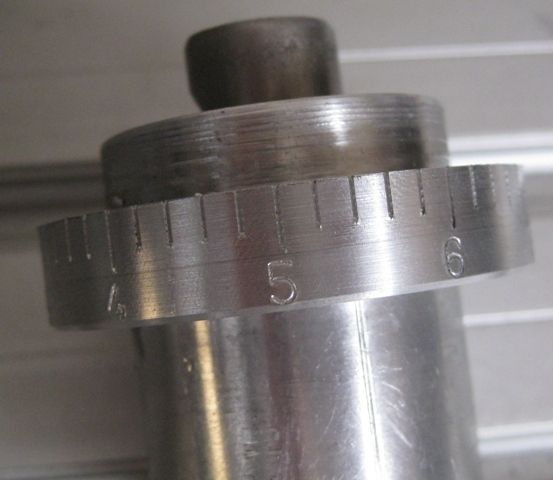
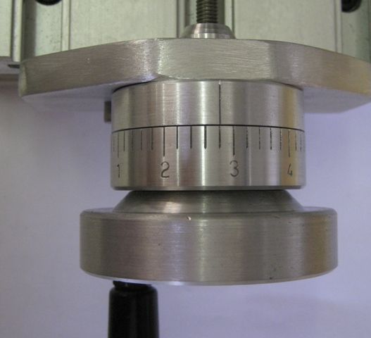
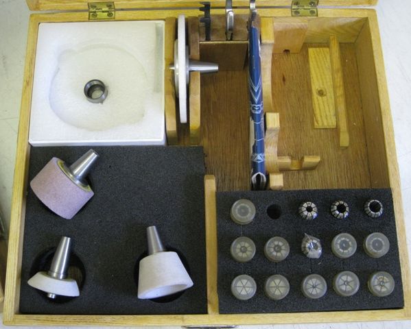
        Aluminium extrusions for the main structure, machine slider rails and blocks for the 3 axes. 1mm pitch M6 Stainless steel threaded leadscrews with split brass nuts. Handwheel graduations giving 0.02mm per graduation. EN8 Spindle, ER16 collet fits on the end and a drawbar for the wheels. Bearings – 10mm ID, 22mm OD, ZZ . Brushless motor, 280kV ( 380RPM/Volt) – 3amps at 8000 RPM. Variable 12-36v DC power supply. A PWM generator for the PWM signal to the RC motor driver (ESC) unit. Speed range at the wheel of 800 RPM to 12000 RPM.

        The motor and drive pulley was dynamically balanced.

        mini grinder front view.jpg

        mini grinder left view.jpg

        mini grinder top view.jpg

        bausch&lomb microscope.jpg

        Leadscrew and split nutleadscrews and split nut.jpg

        slides1.jpg

        holder closeup.jpg

        holder closeup1.jpg

        motor and wheel close1.jpg

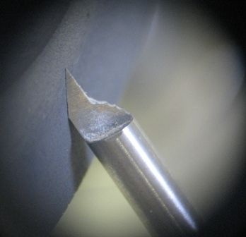
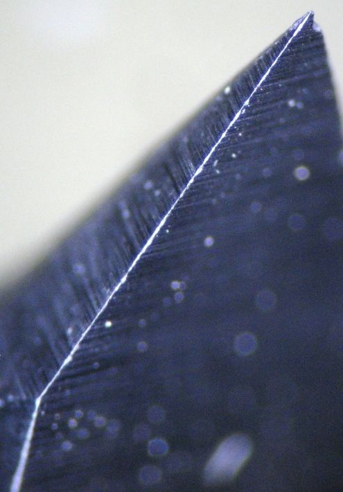
        Engraver tip through Microscope

        engraver tip sharpening1.jpg

        redge1.jpg

        redge3.jpg

        stamping no1.jpg

        stamping no2.jpg

        rough stamped.jpg

        indexing1.jpg

        indexing3.jpg

        dial final.jpg

        Motor Balance Strip.

        balance strip on motor.jpg

        Wheel Weights

        diamond wheel balancing.jpg

        ER11 Toolpost grinderer11 brushles motor toolpost grinder.jpg

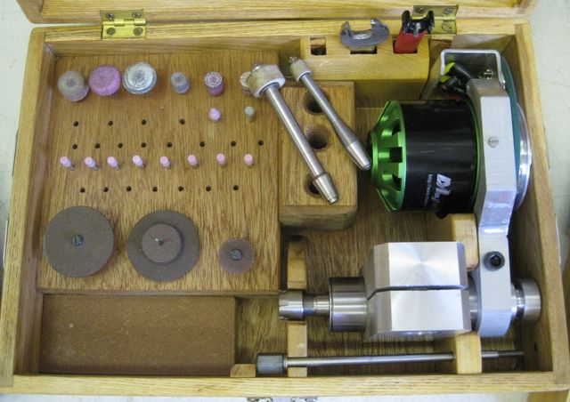
        ER16 Grinder boxer16 brushles motor toolpost grinder.jpg

        The Power supply


        #268640
        Michael Gilligan
        Participant
          @michaelgilligan61133

          Thanks, Joe

          That's very sensible use of the alloy extrusions, and the tilting table yes

          … Lovely job all round.

          A few words about the motor and its drive would be appreciated.

          MichaelG.

          #268643
          Rik Shaw
          Participant
            @rikshaw

            I am always very interested to see other blokes take on T&C machines and this one is fascinating for me as it is capable of doing the "small" stuff. It has certainly given me ideas on making more mods to my machine. Thanks Joe for a great set of detailed photos. yes

            Rik

            #268675
            Joseph Noci 1
            Participant
              @josephnoci1

              Ok Michael, some info on the motor and Drive..

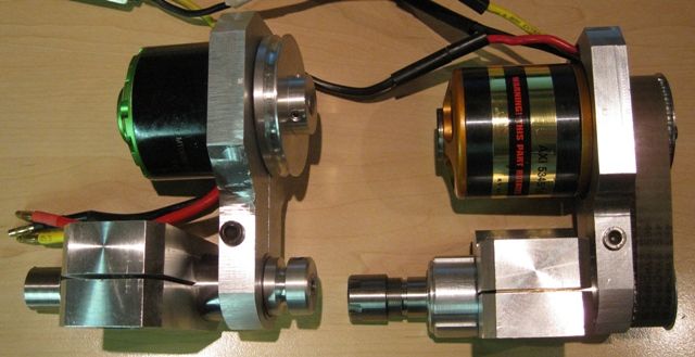
              The Motor is an AXI ( East European) brushless 3 phase Model aircraft motor – 280 RPM/Volt. It is capable of 2.5KW output in an aircraft, sort of 40V in at 100 amps…But not in this application! The max speed of the Grinder results in no more than 4 amps drawn from the DC supply.

              The motor is about 52mm diameter and 60mm long, and is of the 'outrunner' type, ie, the outer casing, containing the magnets, rotates. This gives high torque capability.

              The DC supply, run from the 220VAC mains, can give 8 amps at voltage from 10 volts up to 36volts. This is fed to a brushless motor electronic speed controller (ESC). This connects to the three phases of the motor. Since the ESC requires a Pulse Width Modulated input to control the motor speed, this is provided by a simple 555 timer, generating a pulse every 20 milliseconds, the pulse width being variable between 1 milliseconds and 2 milliseconds ( max speed). The motor has best performance when the PWM value is at 2 milliseconds, so normally I just set it to 2ms, and vary the motor speed using the variable voltage supply. Actually, its the ESC that works best, least losses, when the PWM value is max, so better to give max and vary the DC voltage supply.

              This PWM signal is the signal that in a model plane would normally come from the radio control receiver module.

              At 36volts the motor RPM is around 10000 RPM. The pulley ratio between motor and spindle is 1.25, giving a spindle RPM of around 12600 RPM, more than enough!

              That all there is to it. These motors make very attractive drive units – they are inexpensive, the larger ones have very good torque capability, and the ESC is likewise inexpensive. A source of PWM signal, if you are not up to fiddling with 555's or the like, is, from the same model Shop, a model servo tester – a little box, with a control knob on it, giving said pulse out.

              I have used the same concept on the toolpost grinders, the Hi-speed spindle of my CNC PCB engraver, and on the Sensitive Hi-Speed drill. The one variable power supply / PWM signal generator is used on each machine when required.

              Will try make a post of these as well…

              Regards

              Joe

              #268678
              Joseph Noci 1
              Participant
                @josephnoci1

                Sorry, meant to comment on the use of the tilting table..

                Although the table does allow the Wheel to be angled, I have never needed to do so. The greater benefit of the Table was, in fact, its weight..

                Originally the vertical column was just the extrusion, and even after dynamic balancing the rotating parts, the micro-vibrations was still a problem. The 'chipped' edge of the engraving cutters , as seen in the microscope images, shows this. The minute resonance was a problem. Adding the Table provided a 'massive' inertial mass that stilled all the resonances totally. There is a good reason that the Pro-grinders are all heavy…No more chipped cutters now.

                The chipped cutter would still shave the hair from my arm no problem, but since the cutter is typically at a 10 to 15deg included angle, the tip is very fine indeed. The tip needs the usual relief, and only penetrates the PCB surface by between 40 and 45um – we only want to engrave or isolate the copper layer, around 35um thick. So any chipping of the edge results in burrs on the copper edge, which causes the CNC Engraver floating head to lift minutely, and the cutter lifts, etc. Generally , getting a really good cutting edge take 2 or 3 grinds..

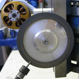
                The grade of Diamond grit plays a big role – a very fine grit is best for the final polish, but bad for tip-regrinds after breakage. And swapping wheels must be done carefully. All my wheels are balanced in situ, and their mounting position on the spindle carefully marked so they go back in the same rotation. And, strangely, I have a CBN wheel which gives me the best results ever when doing these bits – an equivalent diamond wheel, with the same bonding resin, does not do as good – Yes, I know, CBN and Diamond, all dissolving, etc…The temperatures are kept very low, very small, shallow grinds, NEVER a red tip, and so far the CBN wheel has done maybe 60 cutters, each with 2 or 3 grind sessions, with little sign of wear.

                Joe..

                #268679
                Michael Gilligan
                Participant
                  @michaelgilligan61133
                  Posted by Joseph Noci 1 on 27/11/2016 20:41:11:

                  Ok Michael, some info on the motor and Drive..

                  The Motor is an AXI ( East European) brushless 3 phase Model aircraft motor – 280 RPM/Volt. It is capable of 2.5KW output in an aircraft, sort of 40V in at 100 amps…But not in this application! The max speed of the Grinder results in no more than 4 amps drawn from the DC supply.

                  .

                  Many thanks, Joe … that 4 amp draw is the bit that makes it all do-able star

                  I always had a fear that these motors would need to be driven from LiPo sources.

                  MichaelG.

                  .

                  P.S. … Just seen your follow-up note … This all makes good sense.


                  Edited By Michael Gilligan on 27/11/2016 21:01:17

                  #268690
                  Neil Wyatt
                  Moderator
                    @neilwyatt

                    > Yes, I know, CBN and Diamond, all dissolving,

                    No-one seems to have practical problems with this in a hobby workshop, whatever the theory says. As you hint it's probably that we don't work the wheels very hard.

                    Neil

                    #268700
                    Anonymous
                      Posted by Joseph Noci 1 on 27/11/2016 20:56:43:
                      Yes, I know, CBN and Diamond, all dissolving, etc…The temperatures are kept very low, very small, shallow grinds, NEVER a red tip, and so far the CBN wheel has done maybe 60 cutters, each with 2 or 3 grind sessions, with little sign of wear.

                      It's well known that hot iron has an affinity for carbon, albeit probably not a problem with diamond wheels in the home workshop.

                      But what is the problem with CBN? I've used CBN inserts for turning hardened steel (~65Rc) without any apparent issues. The feeds and speeds used are designed to ensure that the shear zone is red hot, but the CBN insert seemed fine afterwards. As one might expect, as they're sold for machining hardened steel.

                      Andrew

                      #268714
                      JA
                      Participant
                        @ja

                        I have been wary of using diamond wheels on steel after being advised by a supplier of such wheels not to use one to grind hardened escapement pallets.

                        JA

                        #268718
                        Joseph Noci 1
                        Participant
                          @josephnoci1

                          Andrew, not really a problem at all. Diamond 'should' be used on carbides and CBN wheels on steels, but that really only applies when working at the engineering limits of these materials, ie, running the temperatures high.

                          Diamond tends to reduce to amorphous carbon when grinding carbide at high temperatures( above 700degC), ie, deep grind, high feed rates and lack of coolant, and tend to 'dissolve' steels at similar temps. CBN wheels are best used on steels at those high temps.

                          The only reason to not use CBN wheels on carbide is that CBN is 'only' about 64% as hard as Diamond, so the wheel will wear a little faster. This may be valid for our kind of work, as the wheels we tend to use are small rimmed, with a thin abrasive layer…

                          Regards

                          joe

                          #268749
                          Anonymous

                            Joe: Thanks for the detailed information, useful to know. At the moment all my grinders (bench, surface, cylindrical and T&C) have AlOx wheels, and one silicon carbide wheel for grinding TIG electrodes. But I may use the more esoteric wheels at some point in the future for the T&C grinder.

                            Andrew

                            #268753
                            Circlip
                            Participant
                              @circlip

                              Might only be metallic "Dust" floating from the wheel, but I think I would have protected rear of outrunner cooling slots.

                              Regards Ian

                              #268801
                              Joseph Noci 1
                              Participant
                                @josephnoci1

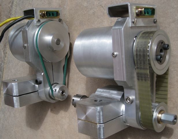
                                Circlip, you are on the mark with your comment. The grinder head you see there is one of two toolpost grinders I made, the other being smaller, an ER11 collet spindle – this one being ER16. The original design catered for a cover – an aluminium Cup-Cake baking thingy…see them without and then with in the pics below –

                                Without

                                Tool post Grinders -1

                                With

                                Tool Post Grinders with Covers

                                The pic does not show the air inlet slots and on the underside periphery of the cover, nor the outlets behind the drive pulley. But it does not work! The air wants to enter at the rear,ie, the backend of the outrunner, so anywhere else, there is no airflow, And then the thing get unbelievably hot in an instant! there is about 3mm clearance tween motor and inner of the cover, and the air friction there rapidly heats the air – the case outer reaches 90degC within 20 seconds! So, the only way is to fit some sort of filter on the rear ofthe cover itself, or fit a fan on the unenclosed motor, blowing the other way..Noise, unbalance again…

                                Still scheming..

                                Regards

                                Joe

                                #268957
                                mick70
                                Participant
                                  @mick70

                                  given me some ideas as we have loads of aluminium extrusion at work.

                                  #268958
                                  Emgee
                                  Participant
                                    @emgee

                                    Hi Joseph

                                    Does the use of a toothed belt drive cause any vibration to the spindle at the high rpm you are using ?

                                    Emgee

                                    #269015
                                    Joseph Noci 1
                                    Participant
                                      @josephnoci1

                                      Hello Emgee,

                                      I believe it does a little, and that is something that cannot be Dynamically balanced out. As I intimated above, even after I balanced the motor and pulley, and the spindle and wheel, separately, I still experienced what I call 'mico vibrations' that hardly registered at all on the vibration sensors, or at least not in a specific angular position, but randomly, albeit they were tiny. That was probably due to the belt itself, rather than the teeth a such. However, the weight of the Tilting Table fixed the problem, as I described.

                                      Joe

                                      #269679
                                      simondavies3
                                      Participant
                                        @simondavies3
                                        Posted by Joseph Noci 1 on 28/11/2016 15:38:38:

                                        The pic does not show the air inlet slots and on the underside periphery of the cover, nor the outlets behind the drive pulley. But it does not work! The air wants to enter at the rear,ie, the backend of the outrunner, so anywhere else, there is no airflow, And then the thing get unbelievably hot in an instant! there is about 3mm clearance tween motor and inner of the cover, and the air friction there rapidly heats the air – the case outer reaches 90degC within 20 seconds! So, the only way is to fit some sort of filter on the rear ofthe cover itself, or fit a fan on the unenclosed motor, blowing the other way..Noise, unbalance again…

                                        Still scheming..

                                        Regards

                                        Joe

                                        Joe,

                                        Really impressed with this as well as your other use of brushless motors – I did something similar as a high speed spindle but I used an inrunner and added a water cooling jacket – which was not ideal (It was written up in a ME a couple of years ago)

                                        Regarding the airflow – or lack of it – are you having an issue with the proximity of the outrunner body and the casing leading to a boundary layer being permanently attached to the motor?

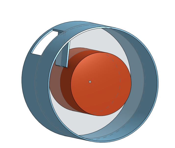
                                        I might be tempted to try a) a larger diameter cover and b) a 'scraper blade almost touching the rotating body and directly in front of a slot which forms the exit path. A corresponding slot or set of tiny holes greater in cross section than the slot to allow air to enter

                                        this quick sketch might make my point clearer (the red is the motor assuming it is turning clockwise, the blue is the casing):

                                        capture.jpgSimon

                                        #269716
                                        Joseph Noci 1
                                        Participant
                                          @josephnoci1

                                          Great Idea Simon! Sort of a tubular Tesla Turbine!

                                          However, there are just too many issues still – The motor wants to suck air in from the rear, and if it is in a cup, with the rear covered then the air has to come around the side to the rear somehow, and I do not see how it will get there – there is maybe a 2 to 2.5mm clearance between the cup inside and the motor outside and it is exactly the boundary layer that is the problem. And if I make holes in the rear then the dust gets in there again, and then I must fit a filter of sorts. I can't easily fit a larger cup – this one is an off-the shell goody from the baking shop, and i have not found others close yet. Also, a larger cup means hacking a mounting for it – I made such a nice recess for the current one..

                                          So, I use the thing, and blow it out when done! Not a long term option, esp when using the grinder as a toolpost grinder doing magnetic steels..

                                          The Plans of Mice and Men..

                                          Joe

                                          #269719
                                          Bazyle
                                          Participant
                                            @bazyle

                                            Perhaps feeding in air from your compressor is the answer. With suitable design the air would be expansion cooled too. Ditching the cover but a cowl for the air feed would get close to the as designed for use in aeroplanes situation.

                                            #498873
                                            Gene Pavlovsky
                                            Participant
                                              @genepavlovsky

                                              Joe, did you make any changes with regards to the motors cooling? I'm planning to make a small toolpost grinder similar to yours, my motor is significantly smaller (SunnySky X2216 III), I'm thinking about using a 40×40 DC fan for cooling.

                                              How do you adjust belt tension in your designs?

                                              I'm also wondering what kind of power connectors you're using between the ESC and the motor. It looks like a D-sub shell with some sort of RC connector installed inside (MR60?).

                                              One thing I don't quite understand, both toolpost grinders have ER collet chucks, however I see some accessories with tapered shafts at the back. How are those mounted?

                                              Did you machine the ER spindles (the inner, rotating parts) yourself, or are they straight shank ER collet chuck extensions like this one?

                                              –Gene

                                              Edited By Gene Pavlovsky on 01/10/2020 14:20:21

                                            Viewing 21 posts - 1 through 21 (of 21 total)
                                            • Please log in to reply to this topic. Registering is free and easy using the links on the menu at the top of this page.

                                            Advert

                                            Latest Replies

                                            Viewing 25 topics - 1 through 25 (of 25 total)
                                            Viewing 25 topics - 1 through 25 (of 25 total)

                                            View full reply list.

                                            Advert

                                            Newsletter Sign-up