WARCO MAJOR QUILL REMOVAL

Advert

WARCO MAJOR QUILL REMOVAL

Home Forums Manual machine tools WARCO MAJOR QUILL REMOVAL

Viewing 5 posts - 76 through 80 (of 80 total)
  • Author
    Posts
  • #559180
    ChrisH
    Participant
      @chrish

      0.07mm is a tad under 0.003" – I have to convert to thous so that it means something to me – which is not bad at all but I have to say I had hoped you'd get better than that! Is there a possibility of being able to micro adjust it? I am looking forward to reading of the traps you experienced, that should be informative.

      I have this afternoon rigged up a mirror for the laser to reflect back onto a target on the mill, but not tested it in anger yet. I set the mirror as true to vertical as I could, I have a fairly accurate level, and then set the laser beam to reflect back onto the mill, it was way off the way I had set it before. Then I put a bit of masking tape over the place where the beam came back and drew round the laser dot to create the 'target'. Then I ran out of time to do anymore, but I will report back here what I find when I do check it out.

      Chris

      Advert
      #559182
      old mart
      Participant
        @oldmart

        You might be able to fine tune the rack to loose some of that error. The other thing you could do is to take measurements at several points along the head travel and make a simple error chart which would account for the error. Exaggerating the 0.07mm on the chart would make it easy to read, and also work at intermediate positions. This would also work even if the rack was not exactly straight, 12 readings would be very accurate.

        It would be interesting to hear from you how the modification was carried out.

        Edited By old mart on 20/08/2021 20:27:30

        #559194
        Terry Turner 2
        Participant
          @terryturner2

          I would have liked a slightly better outcome but the law of ' diminishing returns ' means that I could now put more and more effort into this head alignment issue but achieve proportionally less outcome.

          My machine is after all a round column mill with all its defects and for most of my engineering the level of repeatable alignment I now have is sufficient.

          I may well come back to the alignment question in the future and consider some of the more sophisticated solutions out there but for the time being I want to work on fitting a 3 phase motor, inverter and speed controller.

          So, with grateful thanks to all those who have helped me, not least Edwin White, I will leave the head alignment question for further thought in the future.

          I'll write up the 'traps' I found tomorrow, in the hope that they help anyone who wants to try the Edwin White 'improvement'.

          Best Wishes


          Terry T

          Edited By Terry Turner 2 on 20/08/2021 22:34:02

          Edited By Terry Turner 2 on 20/08/2021 22:34:39

          Edited By Terry Turner 2 on 20/08/2021 22:36:33

          #559211
          Terry Turner 2
          Participant
            @terryturner2

            The Edwin White 'improvement' appears to be a straightforward process capable of producing good results and greatly improve the head alignment problem with round column mills ..but… I found several elements of the work where I could have ended up with a poor outcome…

            1/. The prospect of hand drilling four holes through the rack ( 11mm) and the column ( 17mm) and ensuring that the resultant hole was an accurate tapping size, then countersinking those holes in the rack, troubled me.

            I removed the rack and used the mill to pre-drill two 6.6mm holes ( smaller than recommended for 8mm threads ) top and bottom ( 40mm apart ) and countersink them.

            How did I do that when there was no rack on the mill I hear you ask..? Support the spindle/head on blocks of wood on the table before removing the rack, lock the head clamps and then use the quill control to raise or lower it, ( it is heavy..! )

            I then had a pre-drilled rack which also acted as a guide for the holes I needed to hand drill in the column.

            I ended up with very tight threads and good countersinks.

            2/. My mill stand was actually 0.6 degrees off the horizontal so I had to incline my laser 'target ' by the same amount and I used an electronic gauge to do that accurately. ( Thanks to old mart for the ' heads up' on that. )

            3/. The next, crucial , stage is positioning the head before drilling/tapping holes in the column and I very nearly made a serious mistake here… !

            I drilled and tapped the lower of the four holes in the column and screwed the rack into position. I put the head into its lowest position and aligned the laser on target. I then raised the head to its highest position, moved it to align the laser/ target and prepared to drill / tap the crucial top hole.

            BUT… somehow ….I noticed that when I moved the head up the rack, the rack did not appear to move at all… ? I would have expected the upward movement of the head to 'shove' the rack across as it went higher and it did not…???

            There was a a 1.63mm gap between the head casting and the rack, which I was able to measure using feeler gauge blades and I then used those blades to make a shim to correct the problem. I recommend that everyone does this first. Edwin white uses a shim but appears to do it last…?

            More to follow later

            #559301
            Terry Turner 2
            Participant
              @terryturner2

              More elements of the work that could have produced a poor outcome….

              4/. There are dangers associated with 'firing' lasers , even low powered ones, across a workshop but using one with a vertical linear 'target' proved to be very worthwhile. (If the laser is shone into an eye it can cause immediate, irreversible damage and when I was walking across my workshop I forced myself to look at the ground.)

              I used the laser/ target to determine the rack positions and when I had screwed the rack to the column I used the worm drive/ handle to raise the head.

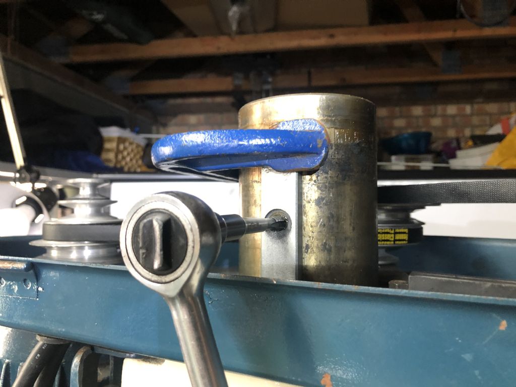
              top clamp with tap.jpg When I raised and lowered the head I expected the laser dot to track along the middle of the vertical target but in the middle of the movement the laser was wavering all over everywhere ?

              I found that even when held top and bottom by two 8mm counter sunk screws the rack was simply not rigid/ strong enough and it was visibly flexing !

              Fixing the rack with another 8mm counter sunk screw in the middle of the toothed section would leave too little metal so I decided to use a 6mm screw with the normal socket head which I turned down to a tight fit on a 8mm hole, which I drilled free hand. That stopped the rack flexing and corrected the error.

              In the future I may consider using one of the other column mill head alignment projects that can be found on the internet but for the time being I shall stick with what I have.

              Best Wishes

              Terry T

            Viewing 5 posts - 76 through 80 (of 80 total)
            • Please log in to reply to this topic. Registering is free and easy using the links on the menu at the top of this page.

            Advert

            Latest Replies

            Home Forums Manual machine tools Topics

            Viewing 25 topics - 1 through 25 (of 25 total)
            Viewing 25 topics - 1 through 25 (of 25 total)

            View full reply list.

            Advert

            Newsletter Sign-up