WARCO MAJOR QUILL REMOVAL

Advert

WARCO MAJOR QUILL REMOVAL

Home Forums Manual machine tools WARCO MAJOR QUILL REMOVAL

Viewing 25 posts - 51 through 75 (of 80 total)
  • Author
    Posts
  • #557587
    old mart
    Participant
      @oldmart

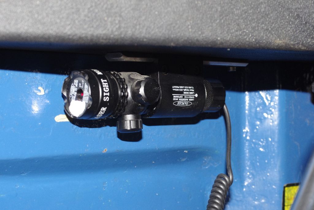
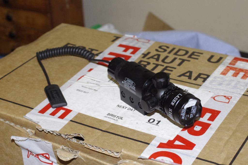
      _igp2799.jpgThis laser for a gun has been on the drill mill for years. The beam reflects off a window about ten feet away and back to the face of the laser. It can be easy to get 0.002" repeatability. An extension switch dangles from the rear of the laser and has to be squeezed to switch it on, there is never a danger of running the batteries down.

      _igp2798.jpg

      Advert
      #557597
      Terry Turner 2
      Participant
        @terryturner2

        Thanks old mart,

        I had in mind positioning the rack with one tapped screw at the bottom then using the laser to make sure the head is accurately positioned high up, before I drill tap the second screw at the top , thus making sure it is accurate all along its travel.

        I will then add other screws to make sure the rack is rigid al along its position..?

        How does that sound…?

        #557601
        ChrisH
        Participant
          @chrish

          Terry – I purchased a TEC 0.75kW (1hp) 4 pole motor and a Schneider ATV12 0.75kW inverter from Inverter Supermarket. Cost was about £200 three years ago. Had a set-up problem when commissioning and the Technical Support chap from Inverter Supermarket was superb, landed the jumbo over the phone. The installation has transformed the usability of the machine; I would not go back!

          I made up a little control panel to control the inverter, and hence the motor, to give forward, reverse and jog with a variable rheostat to control the frequency and hence speed. Also incorporated a 4 digit display to show quill rpm triggered by a little magnet fixed to the quill pulley passing a sensor.

          Old Mart – my laser is very much smaller than yours and was made to bolt to the underside of a pistol. I don't have the luxury of a pull switch, the on/off switch is just a button on the back and the beam is not reflected back so I tend not to see it and just forget it's on! Interesting you bounce it off a window and back, I had thought of bouncing it off a mirror back to a target on the mill head, the mirror would have to be truly vertical to work I think but I also think it would greatly improve accuracy.

          Chris

          #557603
          old mart
          Participant
            @oldmart

            I have never checked the surface of the window to see whether it is truly vertical, but have thought about a mirror to get a stronger reflection. I did try the laser on the front of the mill head pointing sideways at the other end of the building about 70 feet away, but it didn't seem to be an improvement. Those lasers come from ebay and include a number of mounting options as well as the remote squeeze switch for use with a rifle.

            Terry, you have got your "upper and lower" quill bearing races the wrong way round.

            Edited By old mart on 08/08/2021 20:59:54

            #557656
            Terry Turner 2
            Participant
              @terryturner2

              My ball races are the wrong way round.. ( in the description.. ) Thanks ‘old mart’

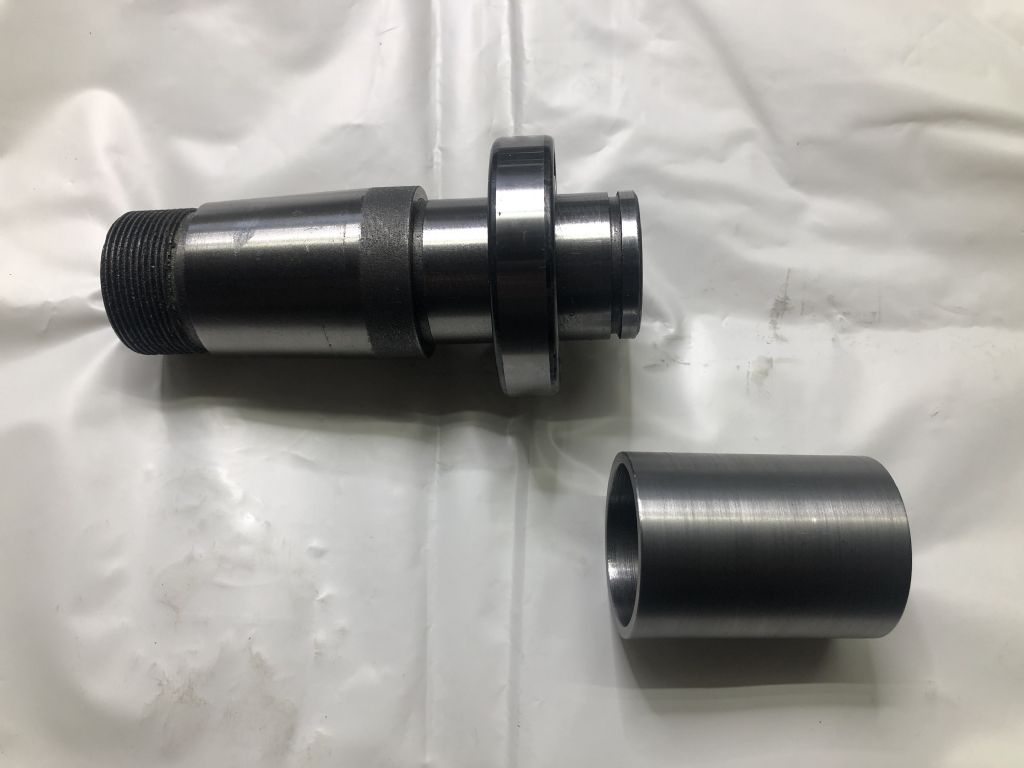
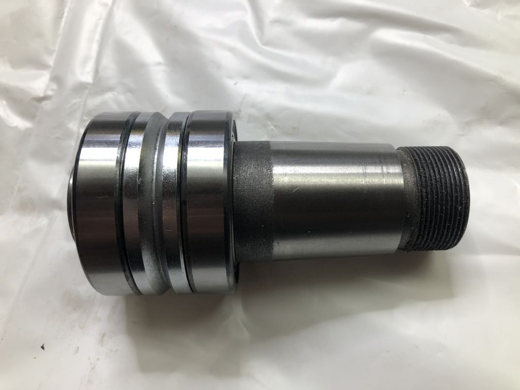
              The rebuild going well , delayed a little because I had to turn a sleeve to press the pulley shaft bearings in place.. I didn’t want to ‘hammer’ them in ,

              Terry T

              #557660
              old mart
              Participant
                @oldmart

                That close up of the lower outer bearing race shows machining marks, not exactly an indicator of quality. I have only replaced the lower bearing in the drill mill, there was a delay in getting an SKF, so I took a chance on a Chinese one, and it was ok. I have been thinking of replacing both bearings in that machine, they are not too expensive and with the front of the head exposed, easy to fine adjust the preload without removing the quill to do it.

                #557710
                Terry Turner 2
                Participant
                  @terryturner2

                  I have all four new bearings for the quill /spindle and the pulley shaft.

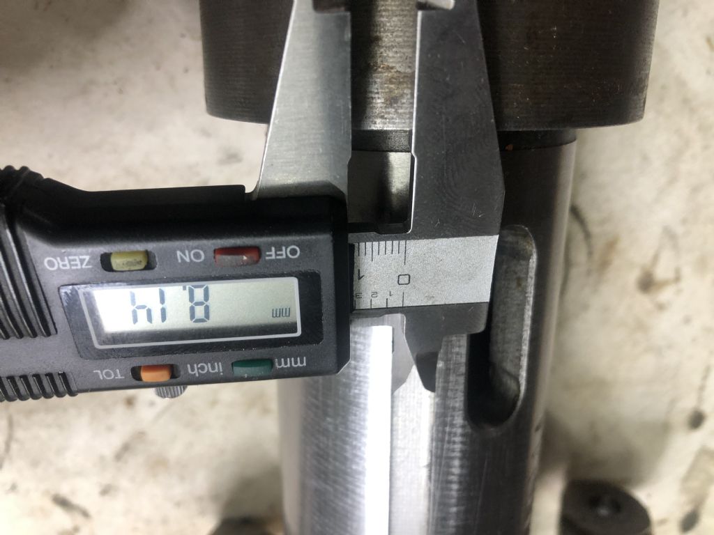
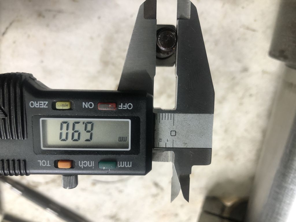
                  Whilst I was waiting for them ( 1 hour from a very local distributor ) I turned up a new anti-rotation ( 10mm ) grub screw as the original was very ill fitting.

                  anti rotation groove.jpganti rotations screw size.jpgSorry they pics appear upside down but you can see that a 6.9 screw will be very sloppy in a 8.14 groove.

                  I then turned a sleeve to fit the pulley shaft bearing inner race so I could press them on to the pulley shaft without any fear of distortion or damage.

                  pulley shaft sleeve.jpg img_9777.jpgThe pulley shaft bearings / shaft are a snug fit into the top of the head, ensuring that you don't set them too far down in to the head ( there is no seating ledge) and feeling/ setting the grub screw on the side of the housing so that it is positioned in the groove in the bearing spacer.

                  #557775
                  old mart
                  Participant
                    @oldmart

                    That antirotation screw on the museum's Taiwanese round column drill mill is unusual in that it's thread is either Whitworth or UNC, not metric.

                    I notice that your spindle is Morse taper and there is an extraction slot for when larger drills are fitted directly to the spindle. That will prevent overpacking with grease alright. laugh

                    Edited By old mart on 10/08/2021 15:45:59

                    #557817
                    Terry Turner 2
                    Participant
                      @terryturner2

                      I have rebuilt the mill.

                      After some bad experiences with lawn mowers I wasn't looking forward to rewinding the quill return spring but it was ok..a much better design.

                      The new/, better fitting, anti rotation screw works well and although I had originally thought that a better fit would prevent the rotational forces being almost entirely taken up by the quill teeth, that is irrelevant if the quill clamp is used properly.

                      So…..new belts on…plug in…switch on…press the green button and ……..NOTHING !!!

                      Checked the microswitches on the pulley cover and chuck guard…….pressed the green button. again but still nothing..???

                      So tomorrow , armed with trusty analogue multi meter , I shall check the circuits and see what is happening.

                      I am not too worried as I am expecting delivery of a 3 phase motor and inverter/ speed controller , as the final part of my improvements so the existing electrics will be stripped out anyway.

                      Whilst I am waiting for the new motor I will do the Edwin White ' improvement' to the head alignment . I'll let you know how it goes…

                      Best WIshes

                      Terry T


                      Edited By Terry Turner 2 on 10/08/2021 21:43:50

                      #557926
                      Terry Turner 2
                      Participant
                        @terryturner2

                        I found the electrical problem easily this morning and the mill now runs…….the metal catch on the inside of the pulley cover wasn't quite pressing the micro switch hard enough…

                        The mill is very smooth and quiet …well worth all the effort.

                        Thanks to everyone who helped / advised.

                        Terry T

                        #557930
                        old mart
                        Participant
                          @oldmart

                          It's very satisfying to hear of a sucessful outcome, your machine is better than new now and everyone has learned something to boot.

                          #557943
                          Terry Turner 2
                          Participant
                            @terryturner2

                            Thanks old mart,

                            I have to say the project has been one of the most enjoyable bits of work I have done for a long while.

                            TerryT

                            #557950
                            DiogenesII
                            Participant
                              @diogenesii

                              That was a useful week's work, Terry,. ..nicely done..

                              #557955
                              Terry Turner 2
                              Participant
                                @terryturner2

                                Thanks Diogenes II, Now on to the Edwin White improvement…

                                I have fitted a laser to my mill so I can accurately measure the angular error over a six metre distance before I start drilling /tapping holes in the column.

                                I will back that up with some dial gauge readings on the quill and then get out my drill.

                                I hope to start later today. I will let you know how it goes.

                                #558145
                                Terry Turner 2
                                Participant
                                  @terryturner2

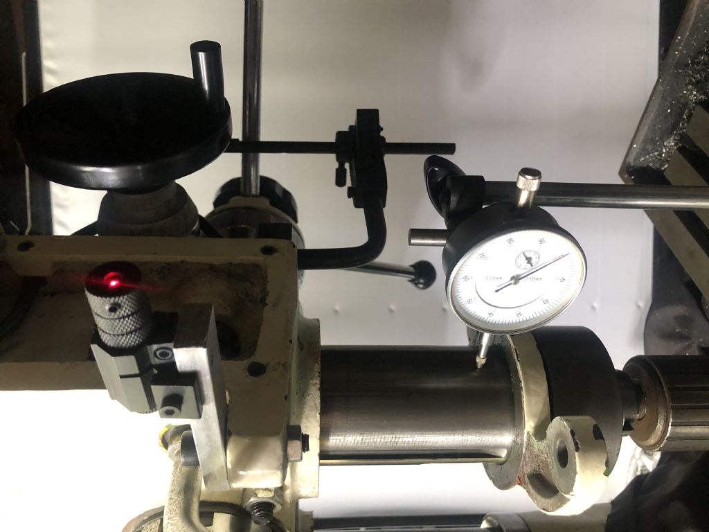
                                  The laser is bolted to the head and has a 4mm wide 'target' 6 metres away. The dial gauge is obviously reading the quill position

                                  laser and dial.jpg

                                  laser target 4mm.jpgBoth methods have already been used by people to successfully reposition the head with good accuracy. ( Thanks to them for sharing the information ) I shall use those methods to measure angular error before I drill / tap the rack and column.

                                  The mill table is 1 degree off horizontal so that will have an effect on the laser measurement at the ' target ' but with both measuring methods working simultaneously , I thought it was worth a test to see what accuracy / repeatability I can achieve.

                                  table level.jpg

                                  Please tell me what you think…?

                                  As ever I greatly appreciate any advice and comment.

                                  Terry T

                                  #558173
                                  old mart
                                  Participant
                                    @oldmart

                                    Your tilt measuring device is not sensitive enough. I was going to suggest that you match the tilt of the line to that of the table, but a tenth of a degree would be on the coarse side.

                                    Assuming 4mm at 6 metres and reducing that to whatever your column to spindle distance is would give an approximate movement of the spindle sideways. Say the column to spindle centre distance was 333mm, then the angle moved would be 0.0382 degrees, and the spindle would move 0.222mm. I use the reflection back to the end of the laser which would double the effective distance.

                                    It would be nice to find a laser with a smaller diameter beam, mine is similar to yours. Estimating the centre of the beam should give better results. Make sure the lens of the laser is clean.

                                    Your dial gauge should be 90 degrees further around the quill, either direction, so that movement in line with the X axis is measured.

                                    Edited By old mart on 13/08/2021 20:09:23

                                    #558176
                                    Terry Turner 2
                                    Participant
                                      @terryturner2

                                      Thanks old mart,

                                      I agree about the size of the laser dot on the ' target ' and will be contacting a friend of mine to see if I can borrow his laser rifle sight, in the hope it is better..?

                                      Also, thanks for your advice about the dial gauge position.

                                      Before I do anything, I will be clamping / shimming the rack , moving the head and testing / comparing the measurements to see how accurate / compatible they are.

                                      Only when I have the measuring 'devices' working will I use them to determine the position at which I drill/tap the rack/column.

                                      Best Wishes

                                      Terry Y

                                      #558184
                                      old mart
                                      Participant
                                        @oldmart

                                        One way of keeping the vertical movement is a version of the aircraft suspension, using a pair of folding links with close fitting bearings. They are normally fitted at the back of the column.

                                        #558188
                                        Terry Turner 2
                                        Participant
                                          @terryturner2

                                          Thanks old mart,

                                          There are indeed a number of methods., some quite complex but I want to try the Edwin White method at the moment.

                                          I am sure that the Edwin White method will give sufficient accuracy for my needs , but I must get the measuring systems right before I carry out the process.

                                          Since my last posting I have found my surveyors distance measuring laser which emits a much more powerful laser beam ………….and a friend of mine, who was trained to work with precision lasers , is searching for one of his many laser emitters that can be focussed to give a fine dot on the 'target'. More about that later.

                                          In the light of your last response though I will try to mount the laser on the centre line of the column so that angular calculations can be more precise…

                                          It's great fun and stirring up some long forgotten trigonometry must be good for me…

                                          Best WIshes

                                          Terry T

                                          #558211
                                          ChrisH
                                          Participant
                                            @chrish

                                            That is the biggest problem with cheap laser pointers – the red dot is quite large with fuzzy edges – or mine seems to be at any rate – which makes determining the centre quite difficult.

                                            I have just purchased a cheap mirror £5.50, sized 500x150mm, from Ikea, (delivered for £2 which saved a trek to the store, bargain!) which I am going to mount on a true flat backing board (ie not bowed like the present target) and mount vertically so as to refect the dot back to mill and try and get it to always return to a fixed target position and see how that goes. I think the problem will lie in getting the set-up right so the mirror is truly vertical and at the correct angle to hit the target, we shall see.

                                            Old Mart – do you have a link to the folding links similar to aircraft suspension links please?  Sounds interesting!

                                            Chris.

                                            Edited By ChrisH on 14/08/2021 11:03:11

                                            #558248
                                            old mart
                                            Participant
                                              @oldmart

                                              Chris, the top picture shows the folding links which keep the upper and lower parts of an undercarriage lined up with each other. I have seen this applied sucessfully to a round column drill mill.

                                              Terry, you will get better results if you shim the mill where it bolts to the stand to get the bed horizontal. If you don't have a reasonable level, a ball bearing sitting on the bed should not move.


                                              **LINK**

                                              Edited By old mart on 14/08/2021 19:15:02

                                              Edited By old mart on 14/08/2021 19:15:30

                                              #558252
                                              ChrisH
                                              Participant
                                                @chrish

                                                Thanks Old Mart – all is clear now, picture worth a thousand words and all that!

                                                Chris

                                                #558384
                                                Terry Turner 2
                                                Participant
                                                  @terryturner2

                                                  I spent my time today ensuring that my measuring systems were as good as I can get them before attempting to carry out any of the Edwin White process.

                                                  The ( expensive ) surveyors laser measuring device only gave a marginally better 'dot'.( The top one in this picture )

                                                  laser comparisonbest.jpg

                                                  When used in comparison with the dial gauge on the quill I found that I could get results which allowed me to carry on.

                                                  I positioned the head .03mm off centre on the gauge and could see the core of both lasers displaced to the left line and return to centre when I 'zeroed' the head /guage position.

                                                  3hundredth guage.jpg

                                                  3hundredth laser .jpg

                                                  The object of the exercise is to measure the lowest position of the head and fix / screw the bottom of the rack there.

                                                  Then raise the head to its highest position, use the laser and gauge measurements to restore it to a correct alignment and fix the top of the rack there.

                                                  I have chosen to use two 8mm countersunk socket headed screws 40mm apart at each location to give the strength necessary.

                                                  Then I should be able to raise and lower the head and watch the laser dots track up the twin lines and watch any displacement on the dial gauge.

                                                  My mill is not horizontal on its stand so I will first measure the true extent of that error accurately ( thanks 'old mart'. ) and then angle the lines to the same degree so that the tracking is a true measurement of the head position. The guage reading should confirm the accuracy..?

                                                  Best Wishes

                                                  Terry T


                                                  Edited By Terry Turner 2 on 15/08/2021 20:12:08

                                                  #558388
                                                  old mart
                                                  Participant
                                                    @oldmart

                                                    I have found that even with a large size laser dot, that it is easy to estimate the centre. Of course, a tiny dot would be nice if possible.

                                                    #559178
                                                    Terry Turner 2
                                                    Participant
                                                      @terryturner2

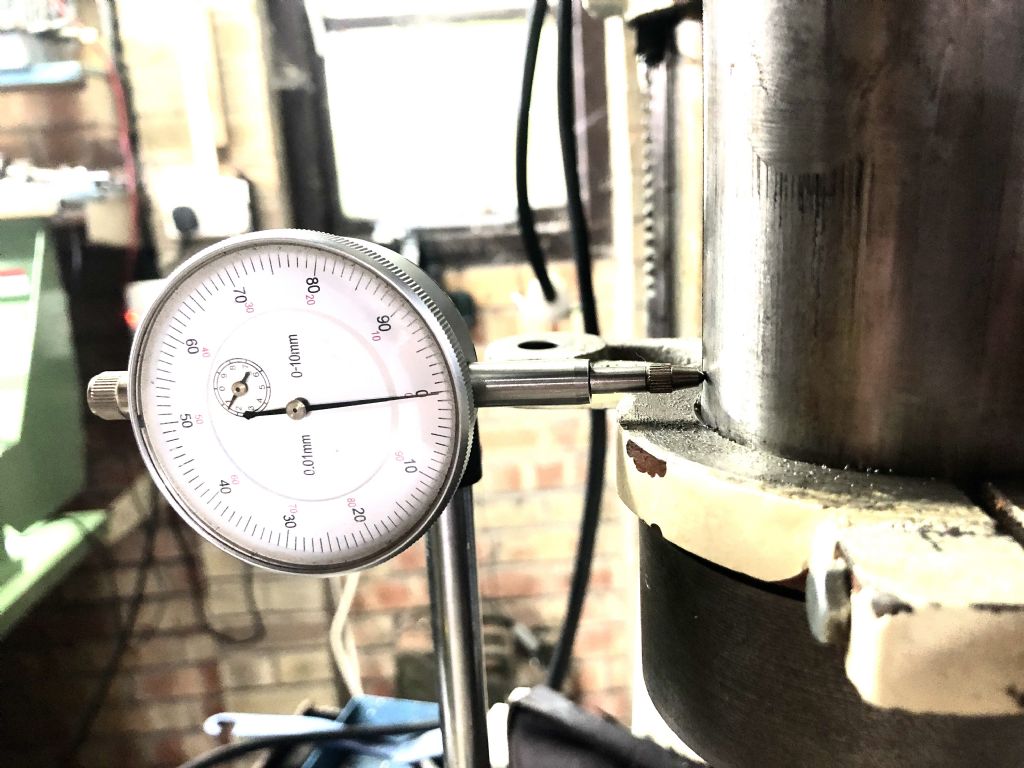
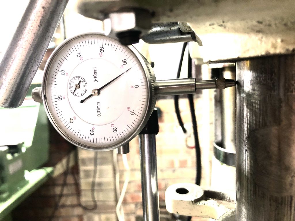
                                                      I have completed the Edwin White 'improvement' on my Chester Eagle round column mill.

                                                      These pictures show results I have repeated several times.

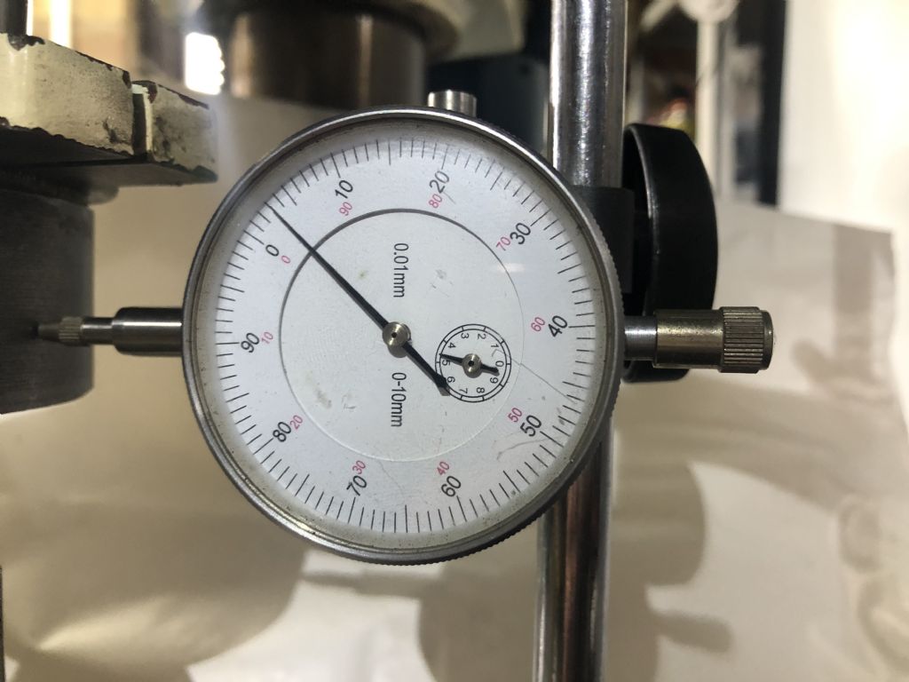
                                                      Lower the quill to its full extent. Place the dial gauge in contact with the lowest part of the quill. Zero the gauge.

                                                      final zero.jpg

                                                      Lower the head using the worm gear. ( Approx 120mm movement ) Read the gauge – 0.07mm deflection.

                                                      final .07.jpg

                                                      I can't recall what the outcome was for Edwin White but for me that is pleasing. ( rounding things for errors in my measurement…about 3 ' thou '  in old money )

                                                      What do you think …? Worth the effort…?

                                                      The process itself is fairly straightforward but there were some real traps on the way… !

                                                      More about that later

                                                      Terry T


                                                      Edited By Terry Turner 2 on 20/08/2021 20:02:13

                                                      Edited By Terry Turner 2 on 20/08/2021 20:03:49

                                                    Viewing 25 posts - 51 through 75 (of 80 total)
                                                    • Please log in to reply to this topic. Registering is free and easy using the links on the menu at the top of this page.

                                                    Advert

                                                    Latest Replies

                                                    Home Forums Manual machine tools Topics

                                                    Viewing 25 topics - 1 through 25 (of 25 total)
                                                    Viewing 25 topics - 1 through 25 (of 25 total)

                                                    View full reply list.

                                                    Advert

                                                    Newsletter Sign-up