Struggling to understand a drawing.

Advert

Struggling to understand a drawing.

Home Forums Beginners questions Struggling to understand a drawing.

Viewing 21 posts - 1 through 21 (of 21 total)
  • Author
    Posts
  • #7694
    Gas_mantle.
    Participant
      @gas_mantle
      Advert
      #196123
      Gas_mantle.
      Participant
        @gas_mantle

        Hi all,

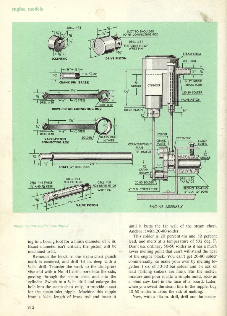
        Can someone please help me understand a small detail in this drawing please.

        I'm not from an engineering background and struggling to understand the measurements to make the eccentric on this little engine I've almost completed.

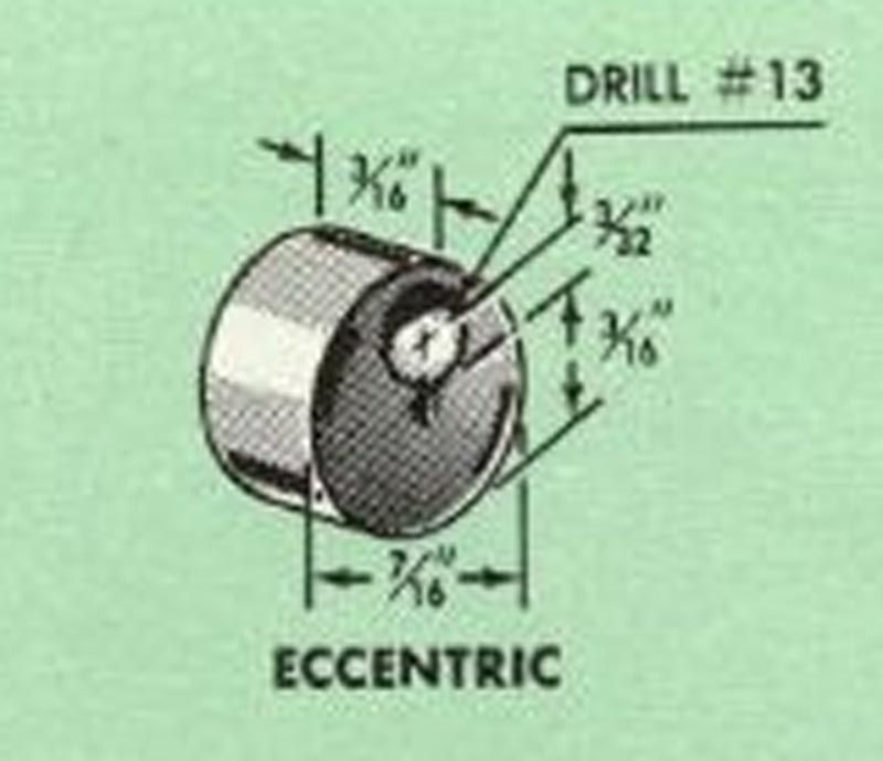
        In the top left corner it shows the eccentric as being 7/16 dia, yet the measurement just to the right of the drawing looks to me as if the radius is 3/16 or is that a measurement from the edge of the bore to the edge of the work ? That to me would seem an odd measurement to include and still doesn't seem to fit with other measurements.

        In the bottom right drawing it says the eccentric is 3/16 stroke am I right in saying that 3/16 is the total movement of the eccentric rod but the throw is to be 3/32 ?

        spoolvalveengine2.jpg

        I don't know what you think but to me the drawing seems a tad misleading and any help would be greatly appreciated

        Many thanks

        Peter.

        #196129
        Anonymous

          I can't see what the 3/16" dimension refers to; it seems to be just plain wrong? I would ignore it. Correct, an eccentric throw of 3/16" means that the hole is 3/32" off centre, as shown on the drawing.

          As an aside, if you're producing work of the quality shown after a few weeks ot using a lathe then there isn't much hope for the rest of us, or me at least!

          Andrew

          #196131
          Ajohnw
          Participant
            @ajohnw51620

            It appears to use the idea that a slightly smaller drill than the required hole size will give fairly precise hole of the correct size so for running fit on 3/16 he would choose a number drill around 0,001" smaller. i have a feeling I would buy reamers to make some of them.

            Going on the above the port in the valve is intended to come out 3/16 long. I know zilch about steam engines but wonder if the stroke ( twice the throw as used here) should be somewhat longer ? Some one on here that is into steam engines should be able to clear that up. Also maybe how much top clearance to leave in the steam chest at the top of the valves stroke.

            John

            #196132
            Michael Watchman
            Participant
              @michaelwatchman91216

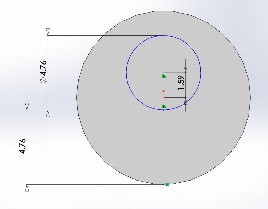
              Hi, I have just took time out at work to model the eccentric based on the dimensions I see. Something doesn't look right. The throw seem too small.eccentric.jpg

              #196134
              Gas_mantle.
              Participant
                @gas_mantle

                Thanks everybody, it's reassuring to know I'm not the only one who things the drawing is wrong somewhere.

                Because of the way I've adapted the engine to suit my own tools and materials rather than mess about with solder etc I'm hoping to sandwich the eccentric between 2 slightly larger discs trapping the eccentric strap between the 2. I'd like avoid having the 2 discs but cant really see a way round it.

                I hope that by having one of the discs and the eccentric made from one piece it will be wide enough to allow for a small grub screw to hold it on the axle and allow for timing adjustment. It should be a simple matter to trap the other disc between the eccentric and bearing post.

                Working in new money I reckon the eccentric needs a 2.5mm throw and I just need to make sure the furthest offset part of it is at the same overall radius from the axle as the outer discs so that I have the width of both parts to tap for the grub screw.

                Does that make any sense ?

                Peter

                Edited By Peter Nichols on 08/07/2015 12:14:31

                #196135
                Capstan Speaking
                Participant
                  @capstanspeaking95294
                  Posted by Peter Nichols on 08/07/2015 10:09:57:

                  Hi all,

                  Can someone please help me understand a small detail in this drawing please.

                  I'm not from an engineering background and struggling to understand the measurements to make the eccentric on this little engine I've almost completed.

                  In the bottom right drawing it says the eccentric is 3/16 stroke am I right in saying that 3/16 is the total movement of the eccentric rod but the throw is to be 3/32 ?I don't know what you think but to me the drawing seems a tad misleading and any help would be greatly appreciated

                  Many thanks

                  Peter.

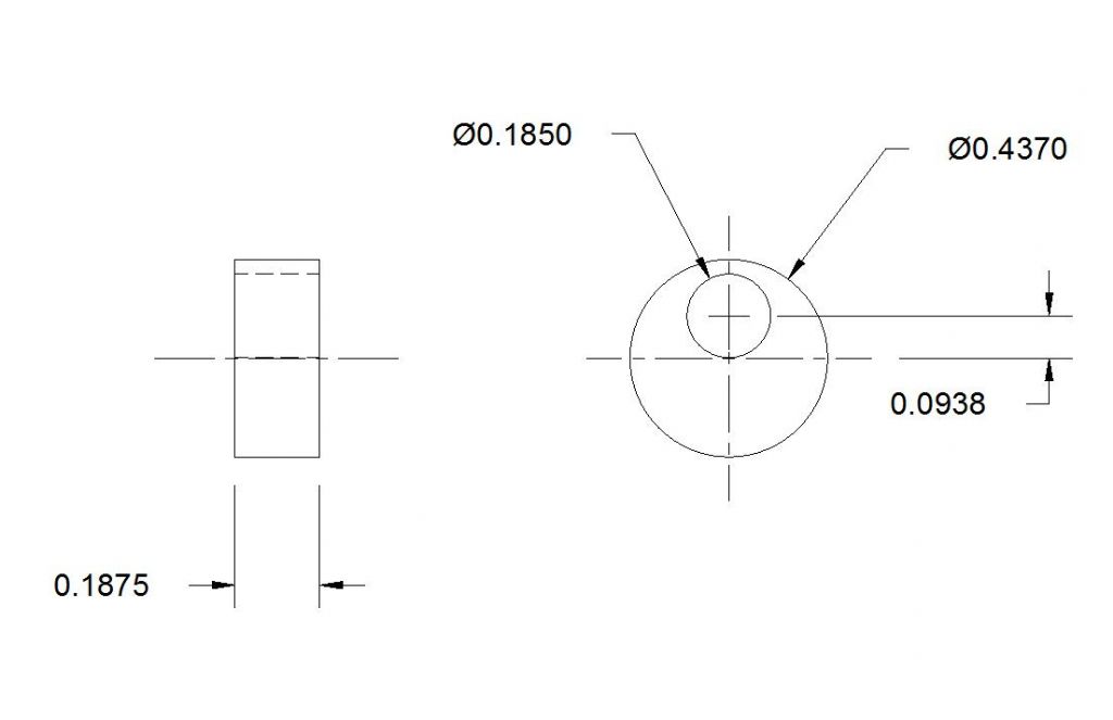
                  It's not you Peter, that "sketch" is amateurish. Given that the stroke is more likely to be an important dimension, I think it is supposed to be as below.

                  drawing.jpg

                  However that is insanely close to the edge. I would increase the o/d and modify the con rod to suit

                  #196140
                  Neil Wyatt
                  Moderator
                    @neilwyatt

                    The stroke of the valve is twice the offset of the hole in the centre of the eccentric.

                    I think it's meant to be 3/16" stroke, it's just dimensioned badly. 3/8" would be way too much.

                    This means the central hole in the eccentric needs to be 3/32" off centre, as illustrated. This means the outer edge of the 0.120" hole is at just under 5/32" from the centre, leaving 1/16" of metal which is plenty in my book.

                    This will only mean the valve opens by 1/32" at each end of its stroke, but I don't think that will be a problem. The critical dimension is the 1/8" at the end of the valve and ensuring that is lined up with the inlet passage at (valve) mid-stroke.

                    I think the 3/32" dimension is a radius for a decorative recess on the eccentric, leaving a rim 1/32" wide. This has no purpose and other wise the engine is very functional, but you can make out such a tiny rim on the drawing.

                    Neil

                    #196141
                    Roderick Jenkins
                    Participant
                      @roderickjenkins93242

                      ve.jpg

                      I agree with Neil. The valve throw is 3/16" as shown on the Engine Assembly drawing so the pin is offset by 3/32". The crank plate is presumably a disc so the 1/32" rim could help reduce friction.

                      I have to say that this is an excellent example of how perspective drawings only provide superficial ease of understanding. The shading has only added to the confusion. I much prefer a nice set of orthogonal views and a cross section where necessary.

                      Rod

                      #196142
                      Anonymous

                        Errr, according to my charts a No. 13 drill is 0.185". If we throw caution to the wind and call it 3/16", that leaves a minimum wall thickness of 1/32". Not much, but probably adequate for the design. Personally I'd drill/ream 3/16" and fit a grub screw (M3?) to affix the eccentric rather than relying on a push fit.

                        Upon closer examination there does indeed seem to be a relief on one side of the eccentric, one up for Neil; although I don't see how the 3/32" dimension relates to it. I still think the 3/32" refers to the throw.

                        Andrew

                        #196145
                        Neil Wyatt
                        Moderator
                          @neilwyatt

                          > according to my charts a No. 13 drill is 0.185"

                          Oh dear, I was looking at No. 31… but yes he's aiming for a push fit for 3/16"

                          > The crank plate is presumably a disc so the 1/32" rim could help reduce friction.

                          I did think that, but the eccentric rotates with the crank 'plate' (disc0, perhaps it goes on the other side.

                          Neil

                          #196146
                          Gas_mantle.
                          Participant
                            @gas_mantle

                            Hi all,

                            Thanks for the help,it's a bit clearer now.

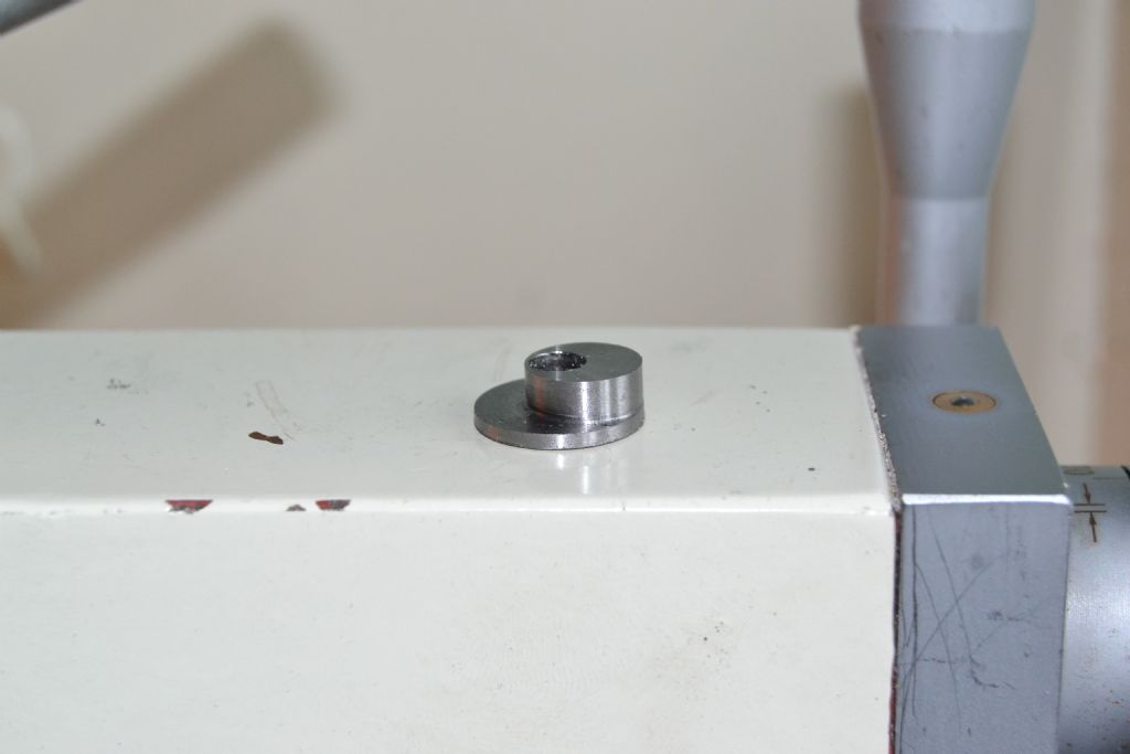
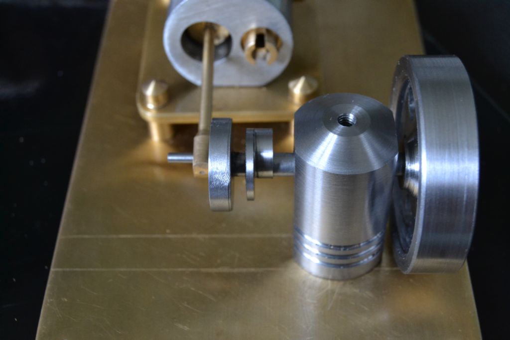
                            What I've done is made an eccentric with a 3/32 throw and a side disc to retain the eccentric strap, I'll then make another matching disc to go on the other side and sandwich the eccentric rod between the 2.

                            The furthest throw on the eccentric and the disc are the same overall radius to the main axle so I intend to fit a small sunken grub screw to cater for timing adjustments.

                            steamer 10 (21).jpg

                            steamer 10 (26).jpg

                            Peter.

                            #196147
                            David Clark 13
                            Participant
                              @davidclark13

                              Bottom right of drawing says 3/16 stroke. You could always use a shouldered pin if you are worried about it breaking out. Are there any other drawings / text you can post? You could always grub screw a collar onto the main shaft rather than add a side disc to the eccentric.

                              #196148
                              Bazyle
                              Participant
                                @bazyle

                                Interesting how a drawing that is perfectly clear in fractions becomes obfuscated by converting to 4 figure decimals. People used to be taught fractions at school.

                                So a 7/16 bar (stock size in the days the drawing was made) needs a hole 3/16 dia (3/32 x 2) with one edge of the hole at 3/16 from the edge. So the middle of the hole which is what you want to mark on the stock to align and drill is shown on the drawing as 3/16 plus 3/32. The author showed the only pertinent dimensions and assumed the reader could add these two fractions in their head without the aid of a Babbage Machine.

                                #196150
                                Gas_mantle.
                                Participant
                                  @gas_mantle

                                  Hi,

                                  David, here's the website I got the full plans from :-

                                  **LINK**

                                  #196153
                                  Bazyle
                                  Participant
                                    @bazyle

                                    I think the "3/16 stroke" on the lower drawing is not the eccentric throw, and is shown as offset from the top of the main shaft seemingly to the centre of a rivet holding the counterweight.

                                    Anyway Peter I think you are making a grand job of redesigning this and should sketch it up and put it on the original website as an alternative. It might be a candidate for making with a bit of cast iron sash weight as the cylinder block.

                                    #196154
                                    Gas_mantle.
                                    Participant
                                      @gas_mantle

                                      Thanks Bazyle,

                                      I started of intending to follow the plans but as I'm just starting off and have limited tool and materials I kept modifying things depending on what I have to work with.

                                      Now the only thing that's original is the basic valve principle, everything else is 'make it up as I go along !'

                                      Edited By Peter Nichols on 08/07/2015 16:24:07

                                      #196174
                                      Johan Clason
                                      Participant
                                        @johanclason52837

                                        Hej Peter

                                        I did like this : Diameter 7/16 minus Stroke 3/16 = 4/16 Split i 2 = 2/16

                                        The hole must be located 2/!6 from top and 5/16 from bottom of excentric.

                                        The strok is the difference : 3/16

                                        #196263
                                        Ian S C
                                        Participant
                                          @iansc

                                          The original eccentric is soft soldered to the shaft.

                                          Ian S C

                                          #196275
                                          Michael Watchman
                                          Participant
                                            @michaelwatchman91216

                                            Someone made a comment about a Babbage machine earlier. I have never heard of this. Just looked on YouTube at the machine in operation. Awesome.

                                            How on earth someone can think up of that lot 150+ years ago is astonishing.

                                            #196361
                                            Ian S C
                                            Participant
                                              @iansc

                                              There's nothing new, someone has at least thought of it, often hundreds of years ago.

                                              Ian S C

                                            Viewing 21 posts - 1 through 21 (of 21 total)
                                            • Please log in to reply to this topic. Registering is free and easy using the links on the menu at the top of this page.

                                            Advert

                                            Latest Replies

                                            Home Forums Beginners questions Topics

                                            Viewing 25 topics - 1 through 25 (of 25 total)
                                            Viewing 25 topics - 1 through 25 (of 25 total)

                                            View full reply list.

                                            Advert

                                            Newsletter Sign-up