Steam pipe connection?

Advert

Steam pipe connection?

Home Forums Help and Assistance! (Offered or Wanted) Steam pipe connection?

Viewing 18 posts - 1 through 18 (of 18 total)
  • Author
    Posts
  • #33725
    Mike Hurley
    Participant
      @mikehurley60381
      Advert
      #507802
      Mike Hurley
      Participant
        @mikehurley60381

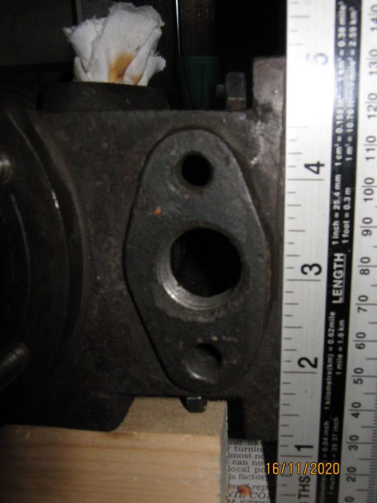
        Hi, Im pretty new to the forum, so apologies if this has been covered before – however I have searched at length both here and on the rest of the internet with no clear answer. I'm restoring a 19th century workshop steam engine and its going well so far (I'll put up a 'ongoing project..' and album when I have time).
        Can anyone assist in identifying the type of steam pipe connection that would fit the input, looking at the attached photo the flange mounting threads are about 2" apart and the port tapped 1/2" x 14 BSP. I ASSUME there would be a union screwed into the port, then possibly some kind of matching conical pipe end clamped by a 'free' flange of some description?
        Most pictures of engines of the same era just show the flange bolted directly to the steam chest, without enough detail to determine how the 'internal' bits are made/put together.
        I have nothing to go on, and have been unable (so far) to find a book, web page or drawings etc that might give a clue to what would be typical in this era.
        Would these be brass or iron? Would copper pipe be the norm? etc. Just if someone could point me at a practical book that covered such topics that would be great!
        Any help much appreciated. regards Mike

        img_0968_s.jpg

        #507811
        Bazyle
        Participant
          @bazyle

          The thread was cut by someone not wanting to go to the expense or trouble of getting the proper flange. As the flange face does not look like it has been machined this was probably at the build stage.
          There are some people on here with lots of full size experience who may offer suggestions.

          #507820
          Howard Lewis
          Participant
            @howardlewis46836

            Prototypical would be a gasket between machined flanges (Pipe and cylinder)

            Non prototypical solution might be flanges, sealed with silicone rubber, and tightened immediately. This is effectively a metal to metal joint with the silicone rubber being used as gap filler. How much pressure it would stand would depend on the out of flatness of the cast face vs the machined face of the pipe flange.

            Howard  (Wireless keyboard cannot even keep up with my slow typing sped )

            Edited By Howard Lewis on 16/11/2020 14:21:05

            #507827
            Dave Halford
            Participant
              @davehalford22513

              Someone may have tapped that 1/2 x 14 BSP intending to use airline heavy galvanised pipe straight in.

              Originally I would have expected copper pipe lagged with asbestos tape. Don't use brass if steam goes through it

              Have you tried on here ?

              Edited By Dave Halford on 16/11/2020 15:19:04

              #507831
              roy entwistle
              Participant
                @royentwistle24699

                Howard I don't think you would have got silicon rubber in the 19th century.

                Roy cheeky

                #507867
                Brian Morehen
                Participant
                  @brianmorehen85290

                  Make a gasket with PTFE sheet , can be bought in various thicknesses…Have used this myself on worn and pitted surfaces works great..

                  good luck.

                  Regards Brian

                  #507890
                  Nigel Graham 2
                  Participant
                    @nigelgraham2

                    Looking in my books, slightly newer than your engine but probably not significantly so, it's probable that the pipes would have been iron or steel, connected to the engine and other parts of the plant by bolted flanges, and to each other by flanges, unions and malleable-iron fittings as appropriate for the particular pipe sizes and installation.

                    The examples in Spooner 1913 show iron screw-on fittings, whose general forms are still readily available simply because no-one has devised any better for fairly general-purpose work, as this would have been.

                    The flanges, union-nipples and their mating flanges, and the T-pieces, elbows etc. are simply screwed onto threads cut on the ends of the pipes.

                    The pipe thread would probably have been and still be BSP, possibly Taper whose length standards give proper taper length without the pipe protruding from the fitting.

                    '

                    However, the same author does also describe copper pipes being widely used for steam supplies to engines, ,but does not cover this aspect in great detail. The material was problematical in larger engines, with pipes several inches and larger diameter. It was certainly common for the auxiliary fittings, drains and the like.

                    The same reference also stresses the installers need allow for expansion. On a small installation with the engine and boiler close together this is probably taken up by a couple of bends or elbows in the steam line.

                    '

                    I am surprised that the pipe boss was left un-machined, and not even particularly fettled, if those pimples are in the parent metal. It is clearly intended for a 2-stud flange, and therefore should have been faced.

                    If intended for a screw-in pipe I would expect the designer to have specified a circular boss thicker than what is there, and no stud holes. Studying my books and from seeing many actual old machines, I doubt that intention in this example – the threading was an installer's idea. .

                    The complete installation would look right with a flanged connection – it is feasible for you to mill it, skimming just enough off to give a fair joint face? Even careful dressing by file would be appreciated by the gasket – either way, be very thorough in cleaning out all the swarf, as the grains could badly damage the working surfaces. Note that the skin of the iron could be hard.

                    I would not rely on silicone rubber sealant lasting long as a gasket especially on that rather rough face, but silicone rubber sheet might be satisfactory.

                    #507924
                    Mike Hurley
                    Participant
                      @mikehurley60381

                      Many thanks for all the suggestions.

                      Dave – I'll definately try the a trawl throgh the site you suggested.

                      I'm trying to keep things as historically true as practicality allows, so wanted to check there wasn't some common layout used that I just wasn't familiar with. It does seem a bit of an enigma in that the boss was never machined flat on either cylinder – but was on the exhaust ports (you can see the shaper cuts): they have a plain hole but a boss with 2 thread holes exactly the same as the subject of this thread. If it was to only be a screwed connection why then not have a circular boss as Nigel suggests,? If it was a case of using a standard cylinder casting they used elsewhere that happened to have a flange-shaped boss, then why tap the holes if not used? I don't see manufacturers of the time doing any process that was unecessary. (Imagine the gruff bowler-hatted foreman with a big red face finding out that they had spent another halfpenny in labour!)

                      I shall ponder further and take all your helpful comments on board. Regards to all

                      #507940
                      JasonB
                      Moderator
                        @jasonb

                        A round flange with typically 4 holes in that situation would not easily fit as the diameter would need to be wider than the minor dimension of the oval boss that you have. Also at that size a 4 studded flange would be a bit OTT.

                        It's possible that the particular installation allowed for a pipe to be screwed straight into the tapped hole, a flange is often better as you can remove a convaulted run of pipework easily without trying to rotate the lot to unscrew it.

                        Also being quite a small delivery it may simply have had one half of a nutted union screwed into it or onto a barrel nipple screwed into the threaded hole if the union was female threaded. This would again allow for easy disassembly.

                        #507951
                        Geoff G
                        Participant
                          @geoffg

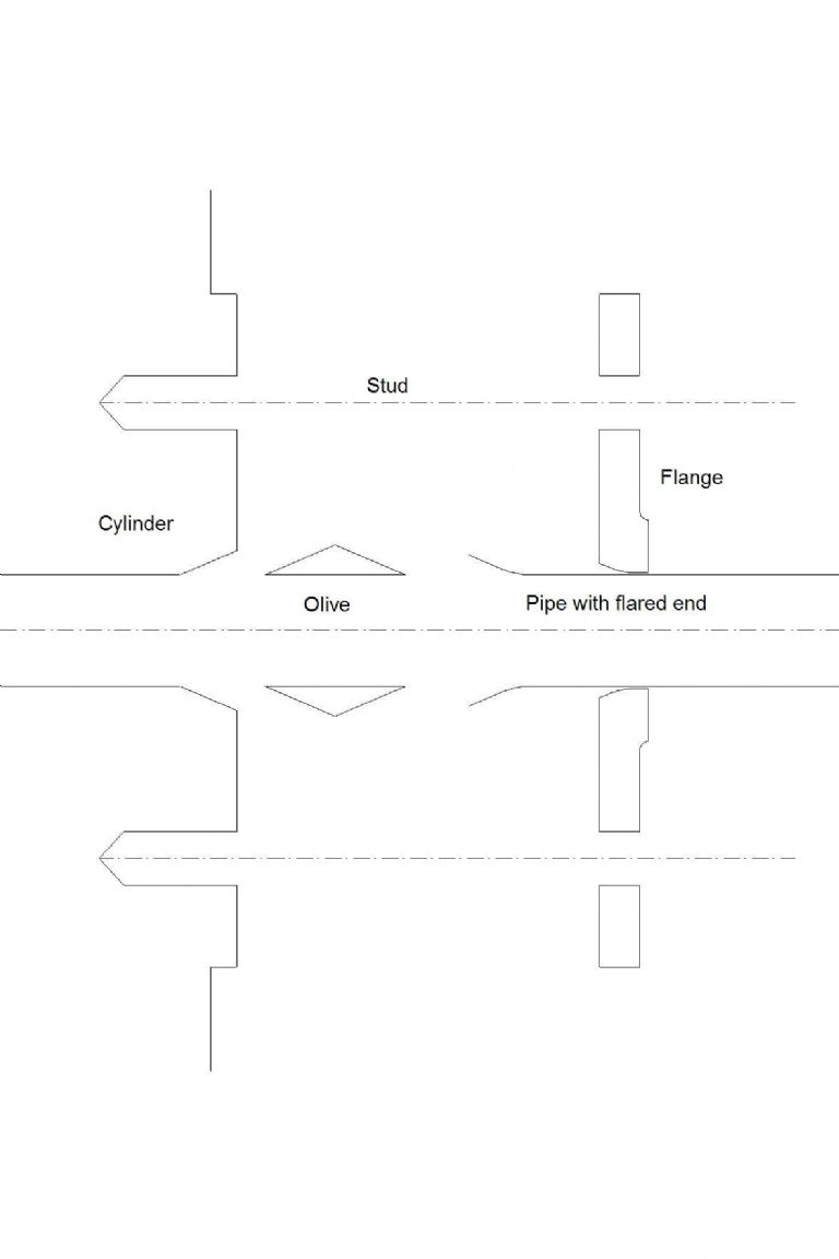
                          Just a suggestion – maybe the taper is the clue. A bronze olive would sit in there and a flare in the end of the steam pipe would fit the other end of the olive. a matching taper in a loose flange would permit the whole lot to be clamped together. I think this sort of connection was favoured in flash steam engine construction. Hopefully there is a basic sketch below.

                          steam pipe connection.jpg

                          #507958
                          Nigel Graham 2
                          Participant
                            @nigelgraham2

                            You could right, Jason, that whoever installed that engine in its past screwed a union nipple into the flange, but I do not think that was the manufacturer's intention. Nor of course was a 4-bolt flange.

                            It was evidently designed to take a 2-stud, oval flange, and plenty of smaller engines and their fittings used those; but it's puzzling why the manufacturer machined the exhaust connection but not the more critical inlet.

                            Not cost-saving – as facing the inlet but not the exhaust would probably have cost the same.

                            So was it somehow overlooked by both the machinist and the inspector, assuming the makers had any reasonable quality control!* Probably. We would naturally assume facing the seating, and drilling and tapping the stud-holes, on one set-up on a milling-machine or a horizontal borer, but that is our mistake. The drilling and facing on this engine were separate operations, as Michael points out the exhaust face was shaped (or planed).

                            I do not believe that thread was original. I think it was put there by the engine's installer, either from new where the customer bought only the engine without installation service; or in some second-hand location done down to a price. There does not seem sufficient metal for it – it looks like no more than 3-4 turns, and concentrates the load on too small an area.

                            '

                            I would advise flattening that oval as well as possible, preferably by machining, and using the proper oval flange and studs, with a suitable sheet-material gasket.

                            The flange fitting the designer probably had in mind was an oval, malleable-iron one with a generous tapped boss that would have been screwed to an iron pipe – a catalogue item. By the early 20C pipe-fittings were readily-available, commercial items; and quite likely were in this engine's time.

                            You could use a copper pipe with a gunmetal / bronze flange silver-soldered on, and from my books of near the time, that would also be in keeping, though you might want to lag the pipes anyway.

                            ++++

                            * Quality control.

                            The phrase might be a lot more recent but late-19C manufacturers were beginning to recognise its importance and to establish processes including rather approximate materials-strength tests. However, there are factors beyond technical to consider.

                            As when the Tay Bridge Disaster investigation and Inquiry revealed that the bridge's cast-iron columns were appallingly badly made; and that the foundry's inspectors often delegated to apprentices who would not have had the nerve to question their supposedly-skilled superiors' shoddy work.

                            We don't know the age and make of this steam-engine, but it's not unreasonable such delegation, perhaps under the guise of training but with poor supervision, lingered for many years longer in many, especially small, companies.

                            So this engine may have slipped through not properly finished, though by simple oversight or bad supervision, not poor workmanship. By the time the unfortunate installer discovered the fault, he probably had no choice but to do the best of a bad job and drive a tap though the thing. Even if he or the customer cared much about niceties in just another day's pipe-fitting, ordering a replacement would have been expensive, whoever paid, and delayed the work.

                            #508044
                            Howard Lewis
                            Participant
                              @howardlewis46836

                              Roy, I did mention not being prototypical!

                              Surprising that whoever was erecting the engine did not file the surface (In those 19th century days, fitters really could fit. A hammer and chisel would get within 5 thou! )

                              Possibly careful filing, if machining is impossible, and some modern non prototype gasket material (rather than red lead string and putty ) may provide an acceptable seal.

                              A flanged fitting would look so much more professional, although the flange may well have been tapped to take the exhaust pipe. At least on the exhaust side the pressure would have been much lower than on the inlet side.

                              Howard.

                              #508146
                              Mike Hurley
                              Participant
                                @mikehurley60381

                                Again, thanks for all the input. Geoff – its not 100% clear from the photo (best I could do) but the 'taper' on the hole doesn't appear to have been machined, Its a bit rough and eccentric so I think it was as cast. With some of these things though its difficult to be sure as parts were heavily corroded externally – not sufficient to weaken the castings structurally more cosmetically.

                                I have great respect for engineers of the era – just look at the work they did with some of those huge pumping beam engines we all like to stare at! but there was also a make-do-and-mend side to it at times, so we have to accept thats the way it was! Its quite feasible an engine like this was produced a 'utilitarian' and you could order it with variants, and this one was built with a screw pipe union to suit whatever steam supply fitting was already available.

                                I seem to be getting a feeling that a straightforward flange bolted on directly with a suitable gasket is going to be the way to go. I shall simply note in the restoration 'log book' the reasoning behind this. I just look forward to manoevering these lumps under the head of my modestly sized Warco mill and TC cutter to lightly skim the boss faces! Keeps me busy during lockdown anyway!

                                Regards to all. Mike

                                #508148
                                JasonB
                                Moderator
                                  @jasonb

                                  I wonder if what has been assumed to be a cast surface is a pitted one that has been cleaned up and painted at some time. The exhaust connections may have stood protected by their flanges but just a threaded pipe going into the inlet would have allowed the uncovered machined face of the boss to rust and pit.

                                  On what is quite a small engine I also wonder if they would have cored the inlet hole giving a "cast face to the edge" or if again rust has pitted it at some time.

                                  #508201
                                  duncan webster 1
                                  Participant
                                    @duncanwebster1

                                    Many moons ago I did a lot of work on preserved narrow gauge locos. For making steam tight joints on badly pitted surfaces we used to make a 'gasket' out of brass gauze, then poke holes in it around the centre hole and weave lead wire through. If you make an odd number of holes and go round twice you get complete coverage. Then dollop loads of Foliac both sides and tighten up. Worked most of the time. I suspect the brass gauze was in effect just keeping the lead wire in place. To get the lead wire we cut 1/8" wide strips off lead flashing, bashed one end roundish with a hammer the repeatedly pulled it through a die-plate with progressively reducing holes until it was round and the right diameter.

                                    Having said all that, the land width horizontal right in the OP photo doesn't look to be very much.

                                    #508216
                                    Nigel Graham 2
                                    Participant
                                      @nigelgraham2

                                      Badly pitted – it could well be.

                                      There is a definite hollow by the 3-1/4 " mark, possibly a few others; but there seem to be pimples on it too, as at 4-1/8 " altitude (look at the shadows). Pimples would be casting artefacts.

                                      The " countersinking " may have been to ease the tap starting and minimise swelling, but is badly chipped, as is the metal around the stud holes.

                                      Looking again at the photo, have the stud holes been lightly spot-faced?

                                      ____

                                      Surpeising where an innocent enquiry about prototypical pipe-fitting could lead… We must be all getting cabin-fever. One is going to have to finish one's post-lunch tea and return to the workshop to look at rusty metal in the, err, metal.

                                      #508646
                                      Mike Hurley
                                      Participant
                                        @mikehurley60381

                                        Thanks guys. After looking back at it yesterday following all the various comments and suggestions, I realised (proving how observent I'm not) that the threaded holes are through into the steam chest, not blind as I had in the back of my mind. This seems to confirm that there must of been something fitted in them or steam woud be blowing all over the place, so a flange & bolts the most likely. A definate conclusion about the threaded BSP hole still remains unclear.

                                        Cannot see any indication of spot-facing around the thread holes.

                                        As I said in an earlier post I seem to be getting a feeling that a straightforward flange bolted on directly (to a cleaned up casting) with a suitable gasket is going to be the way to go. There are so many 'maybes' that after a time you start going round in circles and almost forget why you asked a question in the first place. However the comments from all in the thread have been interesting and I've picked up some useful ideas and tips, so thanks to all. This forum is a really valuable resource. Regards Mike

                                      Viewing 18 posts - 1 through 18 (of 18 total)
                                      • Please log in to reply to this topic. Registering is free and easy using the links on the menu at the top of this page.

                                      Advert

                                      Latest Replies

                                      Viewing 25 topics - 1 through 25 (of 25 total)
                                      Viewing 25 topics - 1 through 25 (of 25 total)

                                      View full reply list.

                                      Advert

                                      Newsletter Sign-up