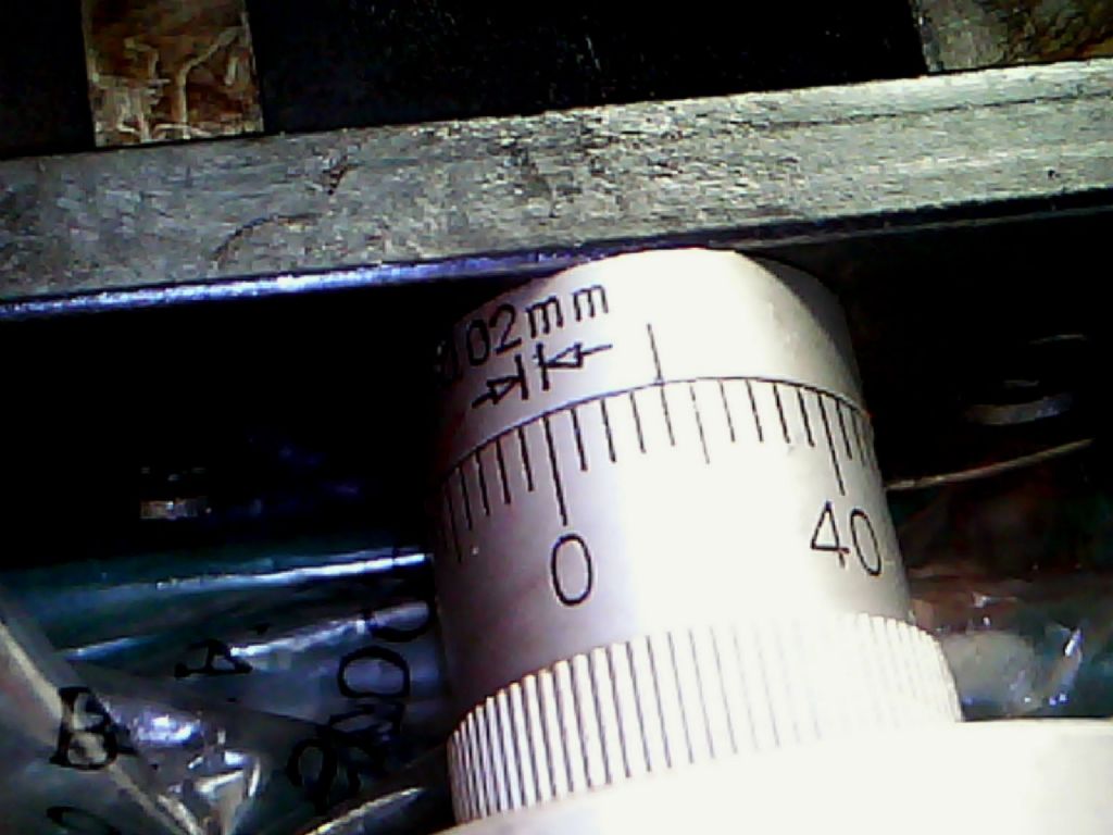
Odd scale on a feed dial

Advert

Odd scale on a feed dial

Home Forums Manual machine tools Odd scale on a feed dial

Viewing 8 posts - 1 through 8 (of 8 total)
  • Author
    Posts
  • #136061
    Gary Wooding
    Participant
      @garywooding25363

      I purchased a small X-Y co-ordinate table some years ago, but only recently decided to commission it on a micro-mill. The scales are metric with 1mm pitch lead screws. Each scale bears the legend >| |< 0.02mm and is divided into 5 sections numbered 0,10,20,30, and 40, each with 10 divisions. One complete revolution of the dial translates into a 1mm movement so, although each dial effectively says 0.50mm, it actually represents 1mm movement. In the photo, the dial is actually set at 0.92 rather than 0.46.

      How confusing is that?

      odd scale.jpg

      Gary

      Advert
      #12219
      Gary Wooding
      Participant
        @garywooding25363
        #136062
        JasonB
        Moderator
          @jasonb

          Yes it would be better if the stamped numbers were 0, 20, 40, 60 & 80.

          My X3s Z axis has similar but in imperial, each division is 0.0005" and its numbered 0-90 whereas one turn only gives 0.050"

          #136066
          John Stevenson 1
          Participant
            @johnstevenson1

            Probably shared components off a lathe where it would then be direct reading.

            Think yourself lucky you have something that works in whole numbers.

            I have a piece of equipment here where it's marked 0, 0.4, 0.8, 1.2, 1.6, 0

            One full turn is 2mm as indicated but trying to get your head round 0.4 divisions isn't easy.

            The 0.5, 1.0 and 1.5 are not even extended marks.

            Pass the 4th axis…………………………

            #136067
            Sam Stones
            Participant
              @samstones42903

              Good morning Gentlemen,

              How about a mill/drill (of Asian origin) with a 3mm pitch on the `X’ and `Y’ axis lead screws? I didn't realise this before I bought it, and it was fully installed.

              I could have become used to the anomaly, were it not for the fact that the dials were marked 0 to 19, ie. 1mm equal to 6.66 graduation lines!!!

              It wasn’t long before I had machined off the engraving and introduced a sensible scale.

              Regards,

              Sam

              #136079
              Gone Away
              Participant
                @goneaway
                Posted by Gary Wooding on 20/11/2013 17:26:05:

                One complete revolution of the dial translates into a 1mm movement so, although each dial effectively says 0.50mm, it actually represents 1mm movement.

                I think I'm confused by your confusion Gary. Seems to me there are 50 small divisions per rev, each 0.02 mm.

                50 x 0.02 = 1mm

                The dial numbers are simply divisions …. they aren't telling you 0 to 0.50 mm but 0 to 50 divisions. I have a similar thing on my (Asian) mill except that mine has an inch-based leadscrew and I have 50 divisions each 0.002". I never found it particularly confusing. Awkward, yes.

                I guess, on your mill, they could have calibrated the large divisions as 0.2 / 0.4 / 0.6 / 0.8 / 1.0 mm instead of 0 – 50 which would have made it slightly easier to use. Ideally they could have divided the dial into 100 small divisions which would make things much easier – but be harder to see. Or they could have used a 0.5mm pitch leadscrew with the existing dial and each small division would be 0.01 mm

                Get a DRO and it all becomes academic (along with allowing for backlash).

                #136196
                Sub Mandrel
                Participant
                  @submandrel

                  My mini lather uses 40 divisions on a 1mm pitch leadscrew. Each division is therefore 0.025mm and effectively 0.001". Much easier to use, for imperial, but not so easy for metric use.

                  The engraving style is exactly as Gary's dial, so probably they are both SEIG machines. I mostly work in imperial, but if I was regularly using metric I would greatly prefer his dials, even if you need to mentally multiply by two (or even by four if using them on the lathe cross slide!)

                  Neil

                  #136203
                  Gone Away
                  Participant
                    @goneaway

                    Posted by Stub Mandrel on 22/11/2013 18:52:45:

                    I would greatly prefer his dials, even if you need to mentally multiply by two (or even by four if using them on the lathe cross slide!)

                    I replaced the crummy cross/top-slide dials on my Myford (ML7) with some dials used on a Far-East micro-mill …. I got them as spares from LMS. The dials have 50 divisions and both ML7 leadscrews are 0.1" per turn …. 2 thou per div. So I have to mentally divide the required cut by 2 for the top slide and 4 for the cross-slide.

                    Not really a problem and the dials look nice and are much easier to read and set and can be zeroed.

                  Viewing 8 posts - 1 through 8 (of 8 total)
                  • Please log in to reply to this topic. Registering is free and easy using the links on the menu at the top of this page.

                  Advert

                  Latest Replies

                  Home Forums Manual machine tools Topics

                  Viewing 25 topics - 1 through 25 (of 25 total)
                  Viewing 25 topics - 1 through 25 (of 25 total)

                  View full reply list.

                  Advert

                  Newsletter Sign-up