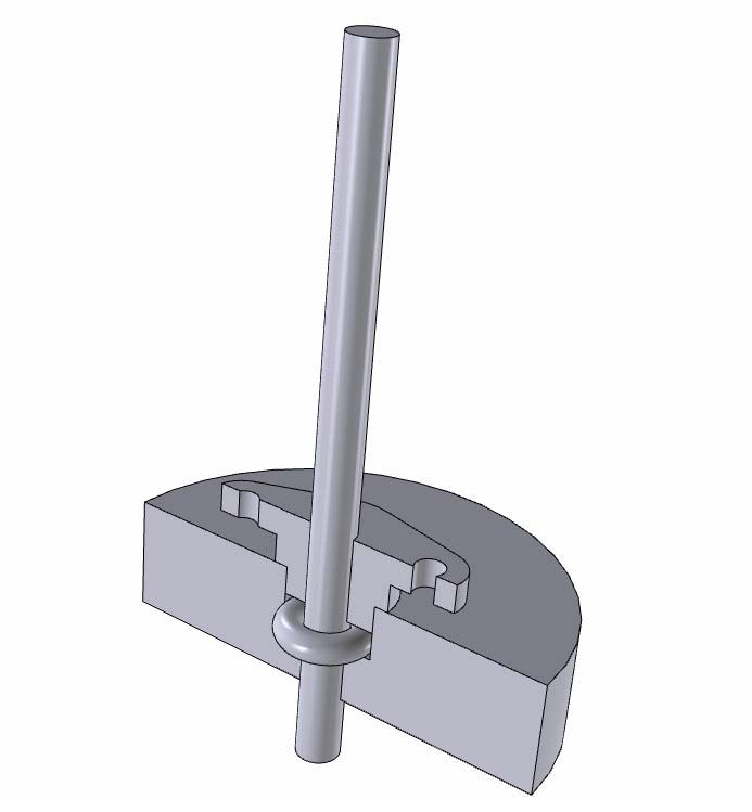
O rings
O rings
- This topic has 19 replies, 8 voices, and was last updated 24 November 2010 at 09:54 by
Gordon W.
Viewing 20 posts - 1 through 20 (of 20 total)
Viewing 20 posts - 1 through 20 (of 20 total)
- Please log in to reply to this topic. Registering is free and easy using the links on the menu at the top of this page.
Latest Replies
Viewing 25 topics - 1 through 25 (of 25 total)
-
- Topic
- Voices
- Last Post
Viewing 25 topics - 1 through 25 (of 25 total)
Latest Issue
Newsletter Sign-up
Latest Replies
- Play on warco mini lathe saddle
- Looking for book on basic strengthening and design methods for steel structures
- Arc’s 25mm indexable end mills…
- Dead Centres?
- Looking for a quality pencil sharpener
- No more Google
- Pre-Setting 4-Jaw Chucks Hack for Quick Centering
- Parting off on a mini lathe
- Mysterious inserts
- Drunk driver broke my workshop!


