Myford ML7 Trileva two speed

Advert

Myford ML7 Trileva two speed

Home Forums Manual machine tools Myford ML7 Trileva two speed

Viewing 25 posts - 1 through 25 (of 29 total)
  • Author
    Posts
  • #92895
    Robin Gibson
    Participant
      @robingibson54443

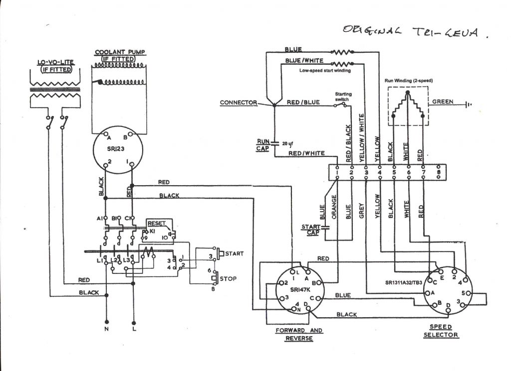
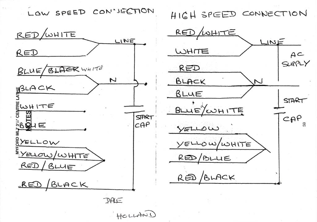
      Hello all, I have a problem with my Myford 2 speed ML7 Trileva which only runs at slow speed. I've had no success with trying to find a wiring diagram for the 2 speed Crompton Motor and the Myford switch in order to check for incorrect wiring etc. I. Just missed discussing it with Myfords before they closed and the standard Myford diagram doen't refer bto the 2 speed un it…. Does anyone have any diagrams of the 2 speed motor and switch please?

      Thanks

      Robin

      Advert
      #11947
      Robin Gibson
      Participant
        @robingibson54443

        wiring help!

        #92989
        Flying Fifer
        Participant
          @flyingfifer

          Robin,

          I`m a little bit confused about this, do you mean the motor itself is 2 speed or are you saying that the Trileva only runs in slow speed ? The Trileva when set up should give 3 speeds when the gear is engaged & a further 3 speeds when disengaged giving a total of 6 speeds in all.

          I fitted a 2 step pulley to the motor on my Myford with a corresponding 2 step pulley on the countershaft which in effect gives 12 speeds via the Trileva. I did this years ago before VFD`s became so popular & if I was younger that would be the way I`d go now, however I can`t see me changing now though it would save b*****ing about looking for the elusive bullwheel hex key.

          Regards Alan

          #93012
          Robin Gibson
          Participant
            @robingibson54443

            Alan,

            Thanks for replying. I was advised when I bought it that it is a two speed motor and on the drum type switch (fitted into the cabinet) it has forward and reverse with low and high speeds available on both via the selector switch which is clearly original. The motor has 5 leads (including the green, presumably the earth). This should according to the Myford brochure and the trileva plate give 6 speeds and another 6 when the back gear is selected .

            The difficulty is that the Myford ML7 and Trileva manual doesn't give any wiring diagrams appropriate for a two speed motor and local sparks I've spoken two say it isn't possible on a 1ph motor! However, I have found other data on the net which says it is though and I do have the physical proof of the machine!

            The trileva works fine on the lower speed though but I simply cannot remember if it worked on all 6 speeds when I bought it. I've now decided to replace the conector box with one which permits easier connections visibility (the original was small and difficult to see if they were made correctly) and will wire it up the same as it was just to check the connections were made correctly.

            For anyone more knowledgable than me with motor electrics, the motor leads are red, black, brown, yellow and green. The motor has a single capacitor and might be a Crompton although it has no nameplate. . It has 4 terminals Z, A, ZA, T and earth. which appears to be the Crompton designation and the manual for the standard states these are start, running, running and start windings respectively.

            All I can think is that the complicated switch somehow links different windings together to get the 2nd motor speed…. Arghh my brain hurts!

            #93015
            Les Jones 1
            Participant
              @lesjones1

              Hi Robin,
              I do not know if dual speed single phase motors exist. If they do there would have to be more than four wires (Plus earth) to them to have a way to select the different speeds. So the motor on your lathe must be single speed. I suspect the lathe originally had a three phase dual speed motor.

              Les

              #93016
              Andrew Moyes 1
              Participant
                @andrewmoyes1

                Catalogue no. 733A, which was current when I bought my ML7 new in 1971, mentions a dual speed motor in the section on the Tri-Leva lathe and shows a drum switch with five positions for forward high/forward low/off/reverse low/reverse high.

                The accompanying pricelist no. S519R dated March 1971 quotes: –

                Two speed motors for use with Tri-Leva speed selector

                60/013A Crompton Parkinson two speed 2850/1425 rpm 0.5/0.25 hp for single phase £27.90

                60/014A As above but for three phase 0.75/0.375 hp. £16.00

                So both single and three phase two speed motors existed. It is widely quoted that the ML7 with white metal bearings should not be run above 1000 rpm but Myford themselves had the Tri-Leva running at a top speed of 1280 rpm. So when I fitted a three phase inverter drive, I had no qualms in fitting a 2850 rpm two pole motor, and doubing the speed range of the lathe. It has worked very well indeed with no signs of overheating. I can highly recommend it other ML7 owners.

                Andrew Moyes

                #93017
                Kevin Bennett
                Participant
                  @kevinbennett25223

                  hi a silly question but has the lever for the back gear moved / slipped and only giving you the low speed range on the head stock

                  Thanks Kevin

                  #93018
                  Gray62
                  Participant
                    @gray62

                    From what has been described with the motor connections, I don't think this is a 2 speed single phase motor.

                    To achieve dual speed in single phase, it is necessary to 'electrically change the number of poles in the motor windings.

                    A Single phase 2 pole motor will rotate at approximately 3000rpm (normally quoted at 2850rpm)

                    A Single phase 4 pole motor will rotate at approximately 1500rpm (normally quoted as 1425rpm)

                    So, in order to achieve dual speed in a single phase motor, there needs to exist a wiring scheme that allows poles to be combined.

                    I am severely rusty on motor theory and mostly this was based on 3 phase technology (almost 30 years ago) which is far easier in terms of speed regulation.

                    I have trawled the net for more info ( out of a morbid sense of curiosity) but have yet to uncover the details of this configuration.

                    If anyone can give further insight, I also would be grateful as I can see applications for this on some of my machines.

                    cheers

                    CB

                    #93019
                    V8Eng
                    Participant
                      @v8eng

                      Hi.

                      My ML7 Tri lever is fitted with a two speed single phase motor, it was supplied to the original owner in that configuration by Myford.

                      The motor has something like 10 wires brought directly out to the terminal box on the rear of the cabinet.

                      There are two capacitors one mounted on the motor, the other one is inside the cabinet near the rotary switch.

                      I did try to get a wiring diagram for this a couple of years ago at a Myford open day, but none seemed to be available, even via their Electrician.

                      Have say that if the motor failed I would replace it with an inverter type drive, which would probably be cheaper than a motor rebuild anyway.

                      I do have a small amount of info on the wiring, and will see if it can be found (might take a few days).

                      Edited By V8Eng on 24/06/2012 19:36:06

                      #93021
                      Trevor Drabble 1
                      Participant
                        @trevordrabble1

                        Robin,

                        If I may add a little to this discussion, like Coalburner my theory is very rusty, but in essence, he is quite correct in that in a single phase motor the speed is determined by the number of poles, assuming the frequency stays constant, the theory being n=f divided by p. ie it is inversely proportional to the number of poles, and the number of poles in use at any one time is achieved by varying the 4 coil connections so as to achieve either 2 or 4 poles as required.Since my computor skils are virtually non-existant, I will try to describe from memory the theoretical connections in words. If you draw a square with a single coil on each side, and starting from the top of the square work in a clokwise direction, notating them as A,B,C and D. If you connect live between A-B and neutral between C-D this should give you 2 poles. If you then change the live connection to between A-D, with the neutral between B-C, then this should give you 4 poles. These 2 arrangements should result in the same flow through B and D on each occassion, and the flow A and C being reversed on the second occassion. I believe this is why you have the 4 wires + earth on your installation. These switching arrangements are perfectly feasible with a propriatory multi-pole switch such as theDewhurst you already have. In the interests of safety, I would suggest you also check this information with a better authority than I, such as a motor or switch manufacturer as well a local electrician/re-wind company who should be well versed in motor installations. In addtion, please ensure that the completed installation is fully tested by a suitably qualified person and that you receive the appropriate test documentation, it will be money well spent. If any of the foregoing are not available to you, then would suggest you investigate alternative solutions

                        I hope you will find the above of some use.

                        Trevor

                        #93032
                        V8Eng
                        Participant
                          @v8eng

                          Hi.

                          I have found what little info I gleaned for my machine, (most unusually I had actually put all the stuff in one place), but sorry to say it bears no relationship to what you describe for your motor.

                          I agree with Phil about getting it sorted by a suitably qualified person.


                          Edited By V8Eng on 24/06/2012 21:27:55

                          #93144
                          Robin Gibson
                          Participant
                            @robingibson54443

                            Thanks to all for your comments and suggestions on this subject, I conclude that as there is a special Myford switch fitted, it should probably switch the motor to give 2 speeds by switching poles. As this doesn't work, it may be that there is a problem with the windings of the motor. The only problem with this hypothesis is the comments from v8eng with his two capacitor motor and 10 leads…

                            The difficulty of getting wiring diagrams of motor and switches may go to show how little we actually retain of older machine design.

                            For now I'll simply stick with the single speed motor with its 3 standard speeds. I have however replaced the original? junction box, with a newer larger one, which makes it easier to connect things up. I appreciate the comments re safety, I do know my limits and will contact a motor electrician before trying any new wiring connections. Very surprising how few motor electricians are around when you ask!

                            #96548
                            Terence Yates 1
                            Participant
                              @terenceyates1

                              Hi Robin, I have all your answers. I purchased a Tri-Leva with a 2-speed motor and no switch. But I have a circuit diagram, you have never seen anything so complicated in your life. The bad news is that you have a standard single speed motor fitted. A 2-speed motor is now rarer than Gold Hens Teeth. It is enormous with at least 10 leads coming from it. As i said before I had no switches, but on the circuit at each of the switches was a number. I rang Santon who made the switches for this originally and the numbers were the part numbers for them. I asked the 64, thousand dollar question, have you got any. Don't be silly, I have worked here for 30 years and have never seen one. But if you want some our Parent company in, ( I think it was) Norway will make you up a pair, but they will cost you an arm and a leg. New switches fitted, she runs like a Swiss Watch. So I have circuit, switch connections, motor wiring diagram. If you want copies e-mail me @ terence.yates44@virginmedia.com

                              You will have to bear with me, my scanner has thrown a wobbly.

                              Regards Terry

                              #96553
                              V8Eng
                              Participant
                                @v8eng

                                Hi Yak.

                                Having read your post I would be interested in seeing that diagram, because my motor certainly fits your description.

                                The difference seems to be that my ML7 has a single (5 position) switch marked fast and slow in both directions plus a centre off, how are your two switches marked up?

                                #96560
                                Robin Gibson
                                Participant
                                  @robingibson54443

                                  Hi Terry and V8Eng

                                  All very interesting and it shows that the information is out there! Thats what is great with the ME forum. Terry I will email you for the details of the diagrams please – they seem to be as rare as hens teeth! Really useful though – I always prefer to have wiring diagrams if possible.

                                  It is really odd that for all the Myford electrical diagrams available, including the Myford manual with a section for the Trilever, all studiously ignore how the two speeds were obtained!

                                  V8Eng, you appear to have the standard Myford switch fitted for twin motor speeds as an optional extra, the same as mine. I have an original sales brochure which clearly shows the switch, but dear Lord, when you get to unclothe the switch its wiring complexity is unbelievable! If you would like a scan of the sales brochure I can readily supply it

                                  I've been told by a few suppliers that 2 speed motors used to be available but at about £280, but haven't been available for years…. I conclude that mine was replaced by a standard single speed motor to give 3 speeds plus another 3 with back gear engaged some while ago. Not sure if its worth pursuing it any more as standard speeds are probably ok for my general model work. It could also be argued that a new inverter drive would supply all ther variable speeds needed I do like the trilever set up though.

                                  Cheers Robin

                                  #96637
                                  Ian S C
                                  Participant
                                    @iansc

                                    A good few years back there was an artical in ME of a chap who for a number of years ran his drill press on two speeds, by using the start windings, until one day it blew up. Ian S C

                                    #96659
                                    Terence Yates 1
                                    Participant
                                      @terenceyates1

                                      Ian SC This motor has a start winding and a run winding for low speed, and a start winding and a run winding for high speed. Two motors in one case, simplfied. From memory one of them is 1/4 hp the other is 1/2 hp. Go to http://www.lathes.co.uk/myfordtrileva/ Here you will find a good description and pictures. Also a super site to explore.

                                      Terry

                                      #96660
                                      Terence Yates 1
                                      Participant
                                        @terenceyates1

                                        Scanner back on line, so I will sort details for scanning ang find out to put them on this site.

                                        Terry.

                                        #96664
                                        Robin Gibson
                                        Participant
                                          @robingibson54443

                                          Thanks Terry look forward to it!

                                          Anyone got a 2 speed motor they don't want?!!!

                                          Robin

                                          #96666
                                          Terence Yates 1
                                          Participant
                                            @terenceyates1

                                            Hi Robin, my lathe had no switches or anywhere on it where they fitted. The new Santon speed change switch has three positions high, off, and low. The reverse has two positions forwards and reverse. I have had to fabricate my own housing, as I could not find a picture of an original. Next time I would go with an inverter and 3-phase motor on single phase. When i first got this lathe the two speed motor was not fitted, (I think someone had bought it to do a conversion, but found it too difficult and gave up) but brand new. Where the wires came out of the motor was a cover, which I took off. Under there were two motor circuits, high and low, so to prove it I twisted the colour coded wires together as in the circuits and banged them into the mains via my rotary transformer and advanced the voltage knob. The start wind started, switch pulled in to go to run winding. Hey-Presto sorted. It all runs happilly now. I now have a standard motor and switch to get rid off.

                                            Terry

                                            Terry.

                                            #96673
                                            Terence Yates 1
                                            Participant
                                              @terenceyates1

                                              How do I upload drawings, circuits etc to this topic?

                                              Terry.

                                              #96679
                                              Robin Gibson
                                              Participant
                                                @robingibson54443

                                                Hi Terry

                                                In the post a reply text box, the icons seem to have the standard paste buttons etc. I'm guessing that if you can do a copy from your files you can then paste them straight into the reply box – it might help if they were saved as pdf files or word files though I'm guessing

                                                I'm liking your brave test regime for the motor! I'm far too timid with eleccy things!

                                                Robin

                                                #96775
                                                V8Eng
                                                Participant
                                                  @v8eng

                                                  Hi Terry.

                                                  I have not tried posting drawings, but I wonder if scanning them and saving as a JPEG might make it possible to put them straight into your photo album on here.

                                                  Regards.

                                                  #96967
                                                  Terence Yates 1
                                                  Participant
                                                    @terenceyates1

                                                    scan10004.jpg

                                                    #96968
                                                    Terence Yates 1
                                                    Participant
                                                      @terenceyates1

                                                      scan10005.jpg

                                                    Viewing 25 posts - 1 through 25 (of 29 total)
                                                    • Please log in to reply to this topic. Registering is free and easy using the links on the menu at the top of this page.

                                                    Advert

                                                    Latest Replies

                                                    Home Forums Manual machine tools Topics

                                                    Viewing 25 topics - 1 through 25 (of 25 total)
                                                    Viewing 25 topics - 1 through 25 (of 25 total)

                                                    View full reply list.

                                                    Advert

                                                    Newsletter Sign-up