Mill Squareness Checking – Odd results (Likely user error)

Advert

Mill Squareness Checking – Odd results (Likely user error)

Home Forums General Questions Mill Squareness Checking – Odd results (Likely user error)

Viewing 24 posts - 1 through 24 (of 24 total)
  • Author
    Posts
  • #259858
    Dan Carter
    Participant
      @dancarter89683

      Hi all,

      Back with another random problem. Have just bought a Chester Super Lux, and have started checking it for accuracy.

      the quill doesn't appear to be vertical in the y-axis (I think a combination of column not vertical and head nodding in towards the column), to the tune of about 0.3mm Y axis movement in about 80mm quill movement.

      I wasn't too worried about this on its own, but then discovered the Y axis tram is almost perfect, < 0.01mm difference between the sides of the table (240mm wide table).

      I don't really understand this – does it mean the spindle is not parallel to the quill ? seems like that would be an uncorrectable problem.

      Is a pretty good chance I have done something stupid, so have attached video clip of the vertical check in the hope someone can point it out.

      Thanks for any suggestions,

      Dan

      Advert
      #24787
      Dan Carter
      Participant
        @dancarter89683
        #259863
        Michael Gilligan
        Participant
          @michaelgilligan61133

          Dan,

          Life would be much simpler if your square was found to be faulty !!

          … I suggest you check it very carefully before doing anything drastic to the mill.

          Here's hoping

          MichaelG.

          #259864
          Dan Carter
          Participant
            @dancarter89683

            Michael,

            Sorry, should have said, similar results with 3 squares and a small angle plate.

            At this point the drastic action would be getting Chester to replace it – although given how hard it was to get on the stand, that is already more drastic than I would like …

            Dan

            #259866
            Michael Gilligan
            Participant
              @michaelgilligan61133

              Oh well … it was a nice thought whilst it lasted.

              I hope it goes well for you.

              MichaelG.

              #259869
              Raglan Littlejohn
              Participant
                @raglanlittlejohn

                Dan,

                How can you be sure the chucks not turning slightly as the quill moves up and down.

                John.

                #259870
                Dan Carter
                Participant
                  @dancarter89683

                  Raglan,

                  Hard to see the tiny force of the DTI lever moving the chuck ? But regardless, can run the quill up and down repeatedly, DTI moves back to zero each time, which would not happen if the chuck had moved.

                  Regards,

                  Dan

                  #259871
                  Michael Topping
                  Participant
                    @michaeltopping17870

                    Dan,

                    I have the Warco Super Major mill which is similar to yours. I have had some of the same issues as you. I trammed the head square with the table but found that I was getting inconsistent results. It took some time to work out what the issues were but in the end I worked out that the head on the column does not move in the same plane as the quill. Obviously you can adjust it side to side using the head tilt facility.

                    My solution has been to shim the column to get it square to the table and then shim the the head carriage to get the quill movement parrallel to the column. It is not easy to do as the head is extremely heavy and not easy to move around.

                    I have now got it to within a thou or so over the quill movement which is fine for the type of work I do. I intend eventually to strip the column of the machine to work out exactly Where the errors are and machine the parts true.

                    Other than that I like the machine a lot.

                    Michael

                    #259872
                    Dan Carter
                    Participant
                      @dancarter89683

                      Michael,

                      Thanks for that – my concern is that given that the Y-Axis tram is currently spot on, but the quill is significantly out, that getting the quill straight will inevitably lead to a significant tram error. if I am understanding my results correctly and the spindle and quill are not parallel, I don't think that can be fixed, but hopefully that is not actually what is wrong.

                      Dan

                      #259874
                      Raglan Littlejohn
                      Participant
                        @raglanlittlejohn

                        Dan,

                        I did not mean the dti could turn the chuck. The spindle must be driven by a splined coupling. There must be slight play if you rotate the chuck clockwise then anti clockwise by hand. that play may be enough to give a false reading. It's also possible theres a spline driving the spindle which is slightly helical. This would not matter in normal use, but would cause the error your seeing.

                        John.

                        #259877
                        Dan Carter
                        Participant
                          @dancarter89683

                          John,

                          Interesting – How about if I use a plunger type indicator held in the chuck, with the plunger horizontal and pointing along the y-axis, this should avoid this issue ? especially if the tip of the plunger is close to the axis of the spindle, so any y-axis effect of a small rotation would be very small.

                          Dan

                          #259913
                          Raglan Littlejohn
                          Participant
                            @raglanlittlejohn

                            Dan,

                            I think what you suggest should result in a much more accurate measurement. It would be better to attach a plunger type indicator to the bottom of the quill, but thats probably not very practical.

                            John.

                            #259914
                            Neil Wyatt
                            Moderator
                              @neilwyatt

                              How are you testing the Y-axis tram? You have to check it by rotating the spindle NOT by moving the table in and out as the latter will almost always give a good result.

                              Put a bar in a milling chuck and check it for concentricity.

                              If it's OK put a square or angle plate on the table against the bar and you should easily be able to see if there's 0.3mm gap over 80mm of bar. If the bar is concentric (and it needs to be) any gap or lack of one should stay constant as the chuck revolves.

                              This will compensate for any twist as the quill is extended.

                              Neil

                              Edited By Neil Wyatt on 08/10/2016 09:12:06

                              #259926
                              JasonB
                              Moderator
                                @jasonb

                                Try it with the quill locked at the top of your square, then unlock and move it to the bottom and then lock again and see if you still get 0.3mm. Could simply be play in the quil slinesl.

                                Edited By JasonB on 08/10/2016 10:08:11

                                #259934
                                mechman48
                                Participant
                                  @mechman48

                                  I'm confused…I thought the axis Dan was measuring was the 'Z' axis… up & down… according to the direction shown in his video

                                  'Y' axis … front to back… 'X axis… left/right to right/left.

                                  It doesn't detract from the error in hand but… thinking … my brain hurts this morning

                                  George.

                                  #259937
                                  Raymond Anderson
                                  Participant
                                    @raymondanderson34407

                                    Dan, I have a similar mill to you I have the Chester Lux and had the same problems as you are having. I had the devils own job but got there in the end. I started by getting the column square to the x and y axis when the head is moved up and down. Then I did the head it's self to get the spindle square when moving it in and out. Took ages but was worth it. Used Devcon steel filled epoxy to bed everything down on to once I was happy. I make a point of never tilting the head left or right to do angles, it is "fixed " Managed to get the column in the x and y to less than 0.02mm over the 350mm length of the square., and the Quill to more or less the same. So it can be done, just takes care and quite a few hours. Is really worth it though.

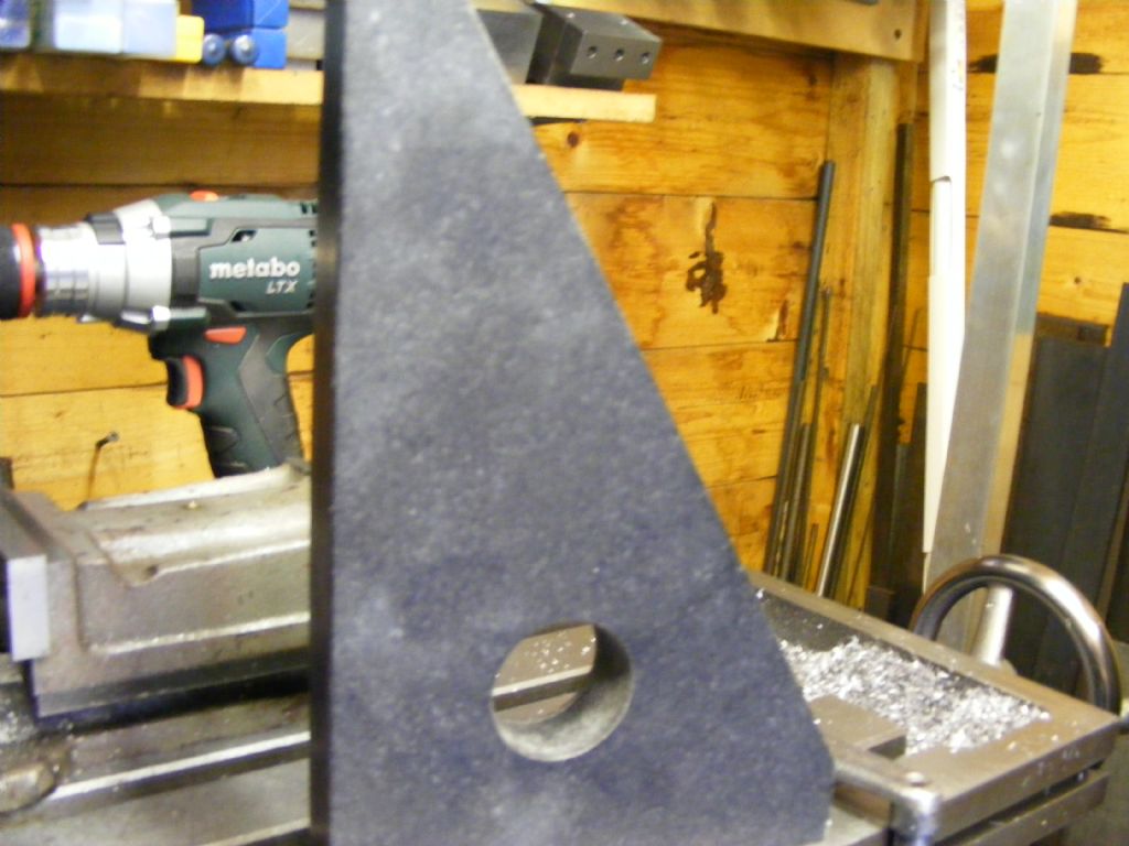
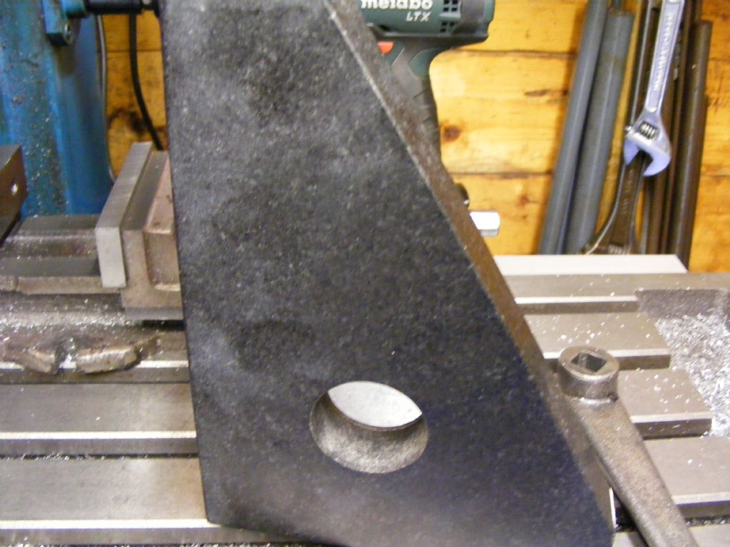
                                    Here is a pic of the Granite Square used, It was made By Crown Windley and is accurate to 0.002mm over the 350mm length and the same over the short length. It is about 50mm thick and being granite is very stable. Not sure if Crown still make the Granite ones. but there will be others that are more affordable out there. crown windley.jpgcrown windley 2.jpg

                                    #259940
                                    Tim Stevens
                                    Participant
                                      @timstevens64731

                                      While you have things apart, look at the connection between the head assembly and the vertical slide. It is likely that this relies on a central 12mm bolt (19mm hex) and a 10mm bolt below it (17mm hex), which sits in a circular slot in the casting. One improvement is to add two more 10mm bolts towards the top of the slot, reducing the tendency of the head to droop or nod. Check too that the flat mating surfaces of head and slide are flat and clean, and that the bolts tighten onto a flat surface square to the bolt axis.

                                      Another cause of head droop is its own considerable weight. It is a simple matter to add a pulley above the head and a counterweight to balance it. Mine (Chester Champion 20V) weighs about 30Kg.

                                      It is also possible to have a cutter which is exactly at right angles to the table, but which moves up and down at an angle from the vertical. This can be because an error in one joint face has been 'corrected' by adjusting another joint. This can result in a hole bored downwards (like drilling) becoming oval as it is deepened, if your cutter has flutes rather than a single point like a boring bar. The accuracy, cleanliness and adjustment of the various gibs (which are likely to be tapered for adjustment) should also be checked. Even though correcting faults is not easy, it is useful to know what the errors are so you can work round them.

                                      Hoping this is helpful …

                                      Tim

                                      Edited By Tim Stevens on 08/10/2016 10:43:29

                                      #260008
                                      Dan Carter
                                      Participant
                                        @dancarter89683

                                        Thanks all for responses.

                                        The prize (Which is just my sincere thanks) goes to John – with the measurement setup adjusted as described, error is now minimal. I am really grateful for this advice, as I was worried I'd have to look at sending the mill back.

                                        Neil – your suggestion was also very helpful for sanity checking (I was already sweeping for tram), as I mounted the bar as suggested, moved up to the square, then used feeler gauge to check no significant y-axis difference with quill up or down

                                        Jason, quill lock does move things around a bit, but as above there was no real error in the first place, just my bad setup.

                                        George – the error I thought I was seeing was horizontal movement of the spindle in the y-axis direction when quill (z-axis) moved.

                                        Raymond – Thanks. I know both head and column are out of square and will need painful adjustment. Now I am confident there isn't a non adjustable problem with the spindle, I can probably bring myself to do it. Can you describe a bit how you did the epoxying please ?

                                        Tim – the Lux already has 3 bolts, at both sides and bottom. The weight of the head is certainly an issue – especially as it has a second motor for head elevation. Whole beast is 278kg, and I dread to think how much is the head.

                                        Thanks again everyone.
                                        Dan

                                        #260025
                                        Raglan Littlejohn
                                        Participant
                                          @raglanlittlejohn

                                          Dan,

                                          Thanks for your kind comments, I'm pleased you got a positive result. I hope you have success with the other problems on your machine.

                                          John.

                                          #260083
                                          Raymond Anderson
                                          Participant
                                            @raymondanderson34407

                                            Dan, here's how I did the epoxy. took the column and head off the base, then roughened the base at the area the column bolts to. Cleaned the area with Acetone then used Lead wire [ iirc it was 2.5mmm Ø ] made a square with the wire on the base, the size of the Column base plate. checked the base of the column to ensure it was smooth then cleaned the area with Acetone. [ I also did the head the same way whilst it was off the column.] Fixed the head back on to the column then bolted the column back to the base. The purpose of the Lead wire is I could then tighten the bolts and they would "squash " the soft wire to whatever was required. All the while this was done using the Crown Granite square. Once I was happy with the readings over 350mm I then used a piece of kit that I was loaned by the local Hilti rep. This piece of kit is used for injecting high strength resin into any cracks that have formed in concrete around a "bund " [ so as to contain any spillage or burst in the tank that may be holding Diesel / chemicals ect. ] I then proceeded to inject the Devcon into the gap between the base and the column base [ I had already bored a 6 mm Ø hole in the column base for the injector.] then once that was done I left it for about a week then took back off the column / head to check all was filled and success total contact. [ I had previously sprayed a film of Ambersil mould release on the Column base so I could break the bond easy.and without any damage to the epoxy ] Put the column / base back together checked the readings and were still as I had hoped for.

                                            The head was done in a similar way I just had to use tiny dabs of super glue to fix the Lead wire in place on account of it being on a vertical surface, then once I was happy did the same again with the resin. Put tape around the outer to contain any overspill.

                                            Reading this thread yesterday prompted me to satisfy me curiosity, so went out with the square and got these readings,

                                            Head up / down the column X axis 16 µ. Y axis 13 µ. [ over 350 mm ] Quill in / out X axis 14 µ Y axis 11 µ. [ over the travel of the quill approx 125 mm ] Tram over the width of the table has not moved as I still get the faint cross hatching when fly cutting. All this setting up / epoxy was done quite a few years ago, and to all intents and purposes has not moved.

                                            I don't suppose you will have access to a Hilti injector, but maybe you could use a syringe , It wont have anything like the pressure of the Hilti but you could inject the resin at various points.

                                            All in took about a good working day in total , fiddly yes, patience testing most certainly yes, but well worth it.

                                            cheers

                                            #260427
                                            Dan Carter
                                            Participant
                                              @dancarter89683

                                              Raymond,

                                              Thanks for the description, definitely sounds worth the effort.

                                              Out of interest do you know how square the table x/y motion is on yours? This is the last thing I am measuring before I decide the thing is basically ok. It is 40µ out over about 145mm (total y travel due to glass scale getting in the way).

                                              This seems worse than I would like, but not something worth sending it back over ?

                                              Regards,

                                              Dan

                                              #260465
                                              Raymond Anderson
                                              Participant
                                                @raymondanderson34407

                                                Dan, Setting up the Granite square with the long 350mm edge on the x axis [ set up so there is no deviation along the x ] the reading along the y axis is 14 µ over approx 190mm . Might be a good idea to remove the tapered Gibs and clean and oil everything then stick them back in and adjust them for best fit, then take the readings again and see what you have. I actually stoned then cleaned and oiled my gibs when I first got the mill just to make sure there was no dirt ect and then adjusted them to give a nice fit. The mill is 10 years old now. and still accurate.

                                                0.04mm does seem a bit "off " especially when it's only over a length of 145mm or so. The machine is certainly capable of far better than that. Certainly you should check the gibs before deciding what your next move is .

                                                cheers.

                                                #260483
                                                Steve Pavey
                                                Participant
                                                  @stevepavey65865

                                                  As well as Raymond's excellent description, there is a YouTube video by Stefan Gotteswinter that shows how he used epoxy for aligning the head, which you may find useful

                                                  Edit I would embed the video but my iPad and the instructions given by the forum software come from different universes

                                                  Edited By Steve Pavey on 11/10/2016 18:33:11

                                                  #260733
                                                  Dan Carter
                                                  Participant
                                                    @dancarter89683

                                                    Steve, thanks for that, very useful.

                                                    Raymond, thanks for the measurement. Having cleaned and adjusted as suggested, I seem to have made things worse ! Having said that, I am starting to doubt my measurement. I think I will actually make some chips for a while and then revisit at some point with a granite square like yours.

                                                    While I would like the machine to be as accurate as reasonable possible, the stuff I want it for doesn't require any great precision, so it is time to stop stressing over it.

                                                    Regards,

                                                    Dan

                                                  Viewing 24 posts - 1 through 24 (of 24 total)
                                                  • Please log in to reply to this topic. Registering is free and easy using the links on the menu at the top of this page.

                                                  Advert

                                                  Latest Replies

                                                  Home Forums General Questions Topics

                                                  Viewing 25 topics - 1 through 25 (of 25 total)
                                                  Viewing 25 topics - 1 through 25 (of 25 total)

                                                  View full reply list.

                                                  Advert

                                                  Newsletter Sign-up