Lathe gears

Advert

Lathe gears

Home Forums General Questions Lathe gears

Viewing 25 posts - 1 through 25 (of 36 total)
  • Author
    Posts
  • #106540
    James Hannabuss
    Participant
      @jameshannabuss68871

      Hey there I'm in need of some help I'm new to this site so I'm sorry if I put this in the wrong place. I've recently acquired a Clarke cl500m lathe and it's was in bits I've payed penny's for it as the previous owner had stripped it down almost completely, but when I fetched it he had lost all the screw cutting gears and gear from the spindle to the milling head. I was wondering if anybody on here has got one of these lathes could you please tell me sizes (outside diameters and number of teeth) of the gears so I can make a set. Also the gear that drives the milling head of the spindle is it the same size as the one on the bottom of the milling head?

      Advert
      #22376
      James Hannabuss
      Participant
        @jameshannabuss68871
        #106636
        Sub Mandrel
        Participant
          @submandrel

          Hi James,

          I have found Clarke's spares service very helpful when I wanted to buy parts for my CL300M.

          **LINK**

          Neil

          #106645
          James Hannabuss
          Participant
            @jameshannabuss68871

            Hey thanks for the response I've emailed them before for parts and for just the basic parts to get it running it was going to cost me well over 350 quid. (money I've just not got lol). So I've put my knowledge and skills into it and made some custom parts to get the machine running and it does quite nicely. . But I just need the screw cutting gears as i need to put power feed back onto it also I want to make my own set as a gear is something ive never made before and I want to learn how to do it and this would be perfect for it.
            #106648
            Siddley
            Participant
              @siddley

              If you only want power feed I'd be tempted to take a different approach and power the leadscrew electrically.

              #106650
              James Hannabuss
              Participant
                @jameshannabuss68871

                That was my first idea but I've been thinking about it a lot and I will need screw cutting on the machine.

                #106651
                Siddley
                Participant
                  @siddley

                  They aren't the easiest machine to screwcut on – the lowest speed is a bit fast and there is no thread dial indicator so really you have to keep the halfnut engaged and reverse the motor after each pass.
                  I had a CL500 years ago and hated it to be honest, but if you bought it cheap then what the hell ? go for it and the best of luck to you.

                  Isn't there a sticker on it somewhere that gives you the tooth numbers of the change gears ? I'm pretty sure there was on mine. It's got to be in the manual or the parts list. That will get you halfway there.

                  #106652
                  John Stevenson 1
                  Participant
                    @johnstevenson1
                    #106653
                    James Hannabuss
                    Participant
                      @jameshannabuss68871

                      I work on a Colchester master at work and that's what we do there just put the machine in reverse. I know what your saying about the speed doesn't really want to slow down to much for it and that's why I was thinking about a variable speed controlled motor so I can have lower to higher speeds, was just a thought gotta look into it. John Stevenson thank you Id only got the parts list one I'd never got the instruction one and completely forgot about it.

                      Right ok I'm going to sound like a right donut now as I know next to nothing on making gears (that's why I want to learn haha) is there a set rule for figuring out outside diameters of the gears?

                      #106654
                      John Stevenson 1
                      Participant
                        @johnstevenson1

                        James,

                        You got any gears at all ?

                        Reason I ask is they all have to match in pitch.

                        #106666
                        James Hannabuss
                        Participant
                          @jameshannabuss68871

                          I have one that they forgot to take off the machine.

                          #106668
                          John Stevenson 1
                          Participant
                            @johnstevenson1

                            Count the number of teeth and measure the OD, everything can be worked out from this.

                            However after looking at a picture of one of these machines i reckon I have one here but Warco model and if the figures match i can take measure this one up.

                            Out all day so don't expect anything until tonight.

                            #106669
                            Terryd
                            Participant
                              @terryd72465

                              Hi James,

                              The size of a gear is determined by the 'Diametral pitch' (used for imperial gears) or 'Module' (metric gears). The diametral pitch is the number of teeth per inch of its diameterm Module is DP / 25.4.

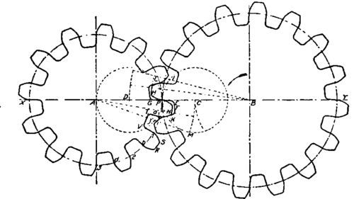
                              Of course it's not quite that simple (it never is) as the pitch diameter of a gear is not the same as it's overall diameter. Instead of 2 gears, imagine two wheels in their place running rim to rim, their diameters are the pitch diameters. To make gears you add projections to the rims of the wheels – the 'addendum', but in order to allow them to mesh you have to make cutouts to clear the new teeth – this is called the 'dedendum', but the pitch diameter is still the same. See, clear as mud.

                              The link below gives a simple introduction and may clarify my poor description above

                              for a simple introduction to gears and modules – which determines the number of teeth on a particular gear size see here. However they use the term 'circumference' which is the same as 'pitch diameter'.

                              For some more complex references see here.

                              Ivan Law's book 'Gears and Gear Cutting' is a good basic introduction – available from Amazon or MHS.

                              Regards

                              Terry

                              #106671
                              jason udall
                              Participant
                                @jasonudall57142
                                Posted by Terryd on 18/12/2012 09:19:57:

                                Hi James,

                                The size of a gear is determined by the 'Diametral pitch' (used for imperial gears) or 'Module' (metric gears). The diametral pitch is the number of teeth per inch of its diameterm Module is DP / 25.4.

                                Of course it's not quite that simple (it never is) as the pitch diameter of a gear is not the same as it's overall diameter. Instead of 2 gears, imagine two wheels in their place running rim to rim, their diameters are the pitch diameters. To make gears you add projections to the rims of the wheels – the 'addendum', but in order to allow them to mesh you have to make cutouts to clear the new teeth – this is called the 'dedendum', but the pitch diameter is still the same. See, clear as mud.

                                ——–

                                Terry

                                Actually that is one of the clearest summaries ( and I have seen a few ) I have seen..

                                Now why cyclodial and envolute ?

                                #106676
                                Les Jones 1
                                Participant
                                  @lesjones1

                                  Hi James,
                                  If you are interested in experimenting there is an electronic approach to replace the lead screw gearing. I have considered the idea but decided that I did not trust the servo system to keep an accurate enough phase relationship between the spindle and the lead screw. If you are interested have a look at This forum.

                                  Les

                                  #106677
                                  Russell Eberhardt
                                  Participant
                                    @russelleberhardt48058
                                    Posted by jason udall on 18/12/2012 09:43:59:

                                    Now why cyclodial and envolute ?

                                    Cycloidal gears give very low friction so are used in such things as clocks where the lkarge wheels drive the small pinions. However if the spacing of the centres is not exact (for example as a result of wear) they are no longer constant velocity and become noisy.

                                    Involute gears are more robust, the spacing is less critical, and they are better for power transmission.

                                    Russell.

                                    #106678
                                    Terryd
                                    Participant
                                      @terryd72465

                                      Hi Jason,

                                      Thanks for the kind comment. sorry about the length of this posting but you did ask wink 2.

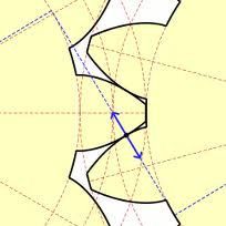
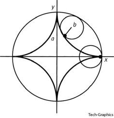
                                      Cycloidal and involute are two types of geometric curve. A gear tooth in profile can have part of one or other of these shapes. Gears in mesh should have the same profile to prevent wear..

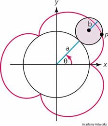
                                      Imagine a bicycle wheel, the tyre valve at the bottom. When you roll the wheel along until the valve is at the bottom again. The curve that the valve makes is a 'cycloid'. If you roll the wheel around a circle it is an epicycloid, roll it inside a circle and it is a hypocycloid. clock gears are usually epi- and hypocycloids using a bit of the curve as the profile:

                                      Cycloid

                                      cycloid.jpg

                                      Epicycloid

                                      epicycloid.jpg

                                      Hypocycloid

                                      hypocycloid.jpg

                                      Cycloidal gears – note the use of a bit of a cycloidal curve for the profile

                                      cycloidal gears.jpg

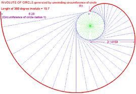
                                      To make an involute tie a pencil to the end of a thread on a fixed cotton reel then draw a line keeping the thread taut and as it unwinds you will draw an involute. Involute gears are the usual profile for power gears.

                                      Involute

                                      involute.jpg

                                      Involute gears using a bit of the curve for the profile of the tooth

                                      involute gear teeth.jpg


                                      These gear profiles are used because the surfaces roll together rather than slide over each other so wear is minimized.

                                      Hope that helps a bit.

                                      Best regards and seasons greetings,

                                      Terry

                                      Edited By Terryd on 18/12/2012 10:48:32

                                      #106679
                                      Ady1
                                      Participant
                                        @ady1

                                        All my gears are mixed DP and I've never had a problem, mainly myford and drummond gears

                                        If you plan on running a 24/7 production line then it's an issue but if you're just a lathe dood who does stuff now and then then you've got at least a decade or two to sort out a perfect matching dp gearset

                                        Until then I reckon you should be able to muddle along on a mixed set


                                        Some gears and gearsets are getting harder to find on ebay

                                        If you spot a weird one it can be worth grabbing it to use on an indexing unit


                                        edit: T6 aluminium seems to be pretty strong if you want to make a lot in a hurry

                                        I fixed my backgear with a chunk of T6 a while back and it's been fine

                                        Edited By Ady1 on 18/12/2012 11:06:07

                                        #106680
                                        Versaboss
                                        Participant
                                          @versaboss

                                          Yes, a good introduction inTerry's (first) link above. However, what irritates me a bit is the first sentence, stating that the module…indicates how big or small a gear is. In my – admittedly quite limited – understanding 'big or small' is referencing the diameter of a gear, or maybe the thickness or weigght (not relevant in this case)

                                          My lathe has Module 1 change wheels, but the biggest has 127 teeth and the smallest 20, and certainly they have not the same size. But nonetheless their module is still ONE for all of them.

                                          But I see how they derived that misleading definition (see 'reference diameter), but I would call the module a measure which indicates 'how big or small the gear teeth are'

                                          Greetings, Hansrudolf

                                          #106681
                                          Ady1
                                          Participant
                                            @ady1

                                            I found this book easy to follow when I first looked at gear cutting

                                            #106682
                                            jason udall
                                            Participant
                                              @jasonudall57142

                                              Thanks Terry.. It was ment as an humorous comment… oh well missed again…

                                              the generation of the curves I remember from TD. ( TOO many years ago) but no one has ever explained why cyclodial forms for clocks ( well the escapement to hands trains) but envolute for power transmistion.. I seem to remember (SOME) clocks use ep for drive to escapment and cy to hands ……now two sets of cutters?….. must have a good reason… and what form used in "clockwork" computers/ difference engins …my guess CY…..

                                              Regards Jason

                                              #106683
                                              Halton Tank
                                              Participant
                                                @haltontank

                                                James,

                                                Just dug my old school test book on Engineering Drawing and in it has a chapter on involute gears. It give the basic theory on gears and formulae for calculating the various bits of a gear wheel.

                                                If you want me to, I can scan the chapter and e-mail it to you (PM me your e-mail address).

                                                Regards

                                                Luigi

                                                #106691
                                                MICHAEL WILLIAMS
                                                Participant
                                                  @michaelwilliams41215

                                                  From a previous thread :

                                                  One of my college lecturers giving the Theory of Machines course had some very large Perspex gears segments – just a few teeth but accurately profiled . Watching the interaction of pairs of these gear segments at a size big enough to see what was going on was very instructive indeed .

                                                  He had examples of involute gears of different pressure angles and also cycloidal , lobal and conformal gears .

                                                  Apart from just seeing how the teeth interacted it was possible to see how the gear meshing action varied with depth of engagement errors .

                                                  Anyone that thinks a gear is a gear and they all work the same way would be astonished if they tried a similar experiment for themselves .

                                                  Two further things that the lecturer pointed out by a simple additional demonstration with a segment of a disk of Perspex were that in the local zone of contact of the various types of gear teeth they all had more or less the same curvature and that it was the local flank angle of the gear teeth that made the meshing gears different in action and more/less sensitive to depthing errors .

                                                  More :

                                                  Clock gears only have to index – even in large clocks the forces involved and the amount of power transmitted are very small . There is wide choice of suitable shapes for clock gear teeth – many early clocks and calculating devices had just simple peg teeth . The triangle shape also works reasonably well after it has been 'run in' – basically the teeth rub themselves into conformal shapes .

                                                  The cycloidal form has several possible origins :

                                                  Trial and error – generations of clockmakers tried this and that and found something that worked .

                                                  Scientific – Some early areas of mathematical study were conic sections and celestial mechanics and most astronomers and scientists would have had a profound knowledge of both . All early celestial mechanics was based on the cycloid and some sharp minds of the day probably saw the similarity between planetary motions and the interactions of gear teeth and used their insights to make practical gears for clocks and instruments . Knowledge of conic sections allowed these gear profiles to be understood further and defined in an easier manner for practical use .

                                                  Religious – Hard to understand now but life for many academics years ago was dominated by religion – not only by the Christian religion but also by the Islam , Bhuddist , Hindu and many other religions . Only a few hundred years ago the motion of ' The Heavens ' was seen as ' Perfection ' ie immutable and not to be questioned . Early mathematicians and astronomers accepted this and fitted their maths around it – hence the cycloidal model of the sun and planets . As far as anyone could tell it was correct anyway – the model worked quite well for predicting the motions . The cycloid itself , since it defined heavenly motion , was itself seen as ' Perfection ' and it was but a small step from there for religiously minded people to consider the cycloidal motion as the pinnacle of mechanical nicety and use it for gears in their clocks and instruments .

                                                  More :

                                                  Power train gears not only have to transmit higher forces and powers – they also have to do so synchronously – as nearly at constant speed as possible for many applications . The involute was deliberately derived scientifically for this purpose .

                                                  I'm pretty sure however that eary millwrights would have observed that wooden cog teeth and as cast iron gear teeth wore themselves into something like involute shapes after a few years use and they may well have made new teeth something like the correct shape long before the scientific derivation .

                                                  Regards ,

                                                  Michael Williams .

                                                  #106694
                                                  Terryd
                                                  Participant
                                                    @terryd72465
                                                    Posted by Versaboss on 18/12/2012 11:07:43:

                                                    Yes, a good introduction inTerry's (first) link above. However, what irritates me a bit is the first sentence, stating that the module…indicates how big or small a gear is. In my – admittedly quite limited – understanding 'big or small' is referencing the diameter of a gear, or maybe the thickness or weigght (not relevant in this case)……………………..

                                                    Greetings, Hansrudolf

                                                    Hi Hansrudolf,

                                                    thanks for pointing that out, I actually meant 'how big the gear teeth are', but of course this is also related to the size of the gear diameter. For example a 60t gear of 0.833mod. would be 50 mm diameter, while a 60t gear of 1.5dp would be 90 mm diameter, hence the size of the gear wheel is relative to the module for a given number of teeth.

                                                    I apologise for my omission and oversight and hope that I have not irritated you so much as to spoil your Christmas celebrations.

                                                    Best regards and seasons greetings,

                                                    Terry

                                                    #106695
                                                    Andyf
                                                    Participant
                                                      @andyf

                                                      If, as is quite common on smallish Chinese lathes, the change gears are Mod 1, then it might (depending on the bore of the gears, or rather the bore of the keyed bushes which fit in them and run on the spindles on the gear quadrant) to use the readily available and cheap acetal gears from a minilathe. I think those gears are 12mm bore, and the bushes are 8mm bore.

                                                      James, examine the gear you have. If its outside diameter (across tooth tips) gear in millimetres is equal to (or just a bit less than) N + 2, where N is the the number of teeth, then it is a Module 1 gear. Of course, if the spindles are missing from the quadrant so you have to make your own, you could make them 8mm diameter.

                                                      The gears for the drive to the milling head drive may be to a different, probably larger, module, but places like HPC or even Technobots may be able to help.

                                                      Andy

                                                    Viewing 25 posts - 1 through 25 (of 36 total)
                                                    • Please log in to reply to this topic. Registering is free and easy using the links on the menu at the top of this page.

                                                    Advert

                                                    Latest Replies

                                                    Home Forums General Questions Topics

                                                    Viewing 25 topics - 1 through 25 (of 25 total)
                                                    Viewing 25 topics - 1 through 25 (of 25 total)

                                                    View full reply list.

                                                    Advert

                                                    Newsletter Sign-up