Just bought an ML7, what should i do first?

Advert

Just bought an ML7, what should i do first?

Home Forums Beginners questions Just bought an ML7, what should i do first?

Viewing 24 posts - 51 through 74 (of 74 total)
  • Author
    Posts
  • #429188
    Shaun Belcher
    Participant
      @shaunbelcher81617
      Posted by not done it yet on 16/09/2019 07:53:57:

      IF it is not, one can always extend the part by a simple threading or soldering operation?

      Quite possible, just have no idea on its construction without looking at it, either way, it looks a decent product.

      Advert
      #429202
      not done it yet
      Participant
        @notdoneityet

        I actually just looked at the product as shown in the above link. It says it is supplied with two nozzles. That means the nozzles will simply be screwed in place? So it would seem an extension would incur a simple threading operation.

        I have no idea of the quality by just looking at the pic, whether good or bad or average. Your latest post, however, seems rather ambivalent – in one part you say you have not yet looked but you then say it looks a decent product.

        #429315
        Shaun Belcher
        Participant
          @shaunbelcher81617
          Posted by not done it yet on 16/09/2019 13:44:34:

          I actually just looked at the product as shown in the above link. It says it is supplied with two nozzles. That means the nozzles will simply be screwed in place? So it would seem an extension would incur a simple threading operation.

          I have no idea of the quality by just looking at the pic, whether good or bad or average. Your latest post, however, seems rather ambivalent – in one part you say you have not yet looked but you then say it looks a decent product.

          it looks decent, but without physically looking at it and seeing how it works/fits, i dont have much idea.

          I hate having to work on photos.

          #429318
          Michael Gilligan
          Participant
            @michaelgilligan61133
            Posted by Shaun Belcher on 17/09/2019 09:48:43:

            Posted by not done it yet on 16/09/2019 13:44:34:

            I actually just looked at the product as shown in the above link. It says it is supplied with two nozzles. That means the nozzles will simply be screwed in place? So it would seem an extension would incur a simple threading operation.

            I have no idea of the quality by just looking at the pic, whether good or bad or average. Your latest post, however, seems rather ambivalent – in one part you say you have not yet looked but you then say it looks a decent product.

            it looks decent, but without physically looking at it and seeing how it works/fits, i dont have much idea.

            I hate having to work on photos.

            .

            Probably worth reading the reviews: **LINK**

            https://www.pressparts.co.uk/OxSiteRating.asp?RatedAccID=105926&ProductID=14443942&FilterMode=5

            MichaelG.

            #437350
            Shaun Belcher
            Participant
              @shaunbelcher81617

              OK, quick update here.

              I finally had my oilers, oil gun and some tooling arrive from overseas and have got the lathe working and made some cuts.

              First thing ive noticed after a bit of use is the lathe is flinging oil everywhere from between the headstock bearing and the chuck.

              Does this mean that the drip rate is too high? I thought i had it rather low myself. How long should a full oiler last before refilling?

              I also assumed that the headstock would have had a drain plug to drain the old oil collected from the oilers, but it looks like its running out and on to the work bench and leaving oil everywhere. Is this typical?

              Right now the main issue is the leadscrews for the top and cross slides.

              I think Im going to need to strip these down and rebuild them.

              Should I convert these to metric while im on the job? Imperial is not much use to me and im just measuring each cut with calipers as I go, and besides the dials dont work properly anyway.

              #437352
              Hopper
              Participant
                @hopper

                Yes they are a total loss lubrication system. Oil just runs out of the bearings and down into the drip tray below.They are as messy as teh British motorcycles of the same era (1940s).

                I try to set my drip lubricators to one drop a minute. Its hard to get them to run that slow though. I only ever fill the glass a quarter full, which is enough to last all day of constant use. Anything left seems to drain out over following days. I use 20/50 engine oil as I find the recommended ISO 32 hydraulic oil is too thin and runs out too quickly. Been using 20/50 on my old Drummond for 50 years or so with no damage done.

                A folded newspaper page or two under the lathe headstock helps soak up the oil.

                Cross slide screws: A lot of the slop can be the way the end float adjustment is set by the graduated dials and nuts and handles etc. Or by worn brass feedscrew nuts that are replaceable.

                I dont know how the dials coould "not work". They have nothing to malfunction. Sounds like they and the retainiung nuts for the handles etc need setting and tightening , which will also remove excess end float.

                You could spend the considerable money and fit metric screws and nuts and dials if it suits your needs better. But you will still have an imperial leadscrew, which is no big drama. You can cut metric threads with it without needing anything but the standard gear set by referring to Martin Cleeves' book Screwcutting in the Lathe. There is some small error in the resulting thread, – but so stupidly small that it is irrelevant to normal home workshop use. (Pedants will arrive at the gate with pitchforks and torches in 5, 4, 3, 2, 1 …)

                #437355
                Shaun Belcher
                Participant
                  @shaunbelcher81617
                  Posted by Hopper on 15/11/2019 09:10:11:

                  Yes they are a total loss lubrication system. Oil just runs out of the bearings and down into the drip tray below.They are as messy as teh British motorcycles of the same era (1940s).

                  I try to set my drip lubricators to one drop a minute. Its hard to get them to run that slow though. I only ever fill the glass a quarter full, which is enough to last all day of constant use. Anything left seems to drain out over following days. I use 20/50 engine oil as I find the recommended ISO 32 hydraulic oil is too thin and runs out too quickly. Been using 20/50 on my old Drummond for 50 years or so with no damage done.

                  A folded newspaper page or two under the lathe headstock helps soak up the oil.

                  Cross slide screws: A lot of the slop can be the way the end float adjustment is set by the graduated dials and nuts and handles etc. Or by worn brass feedscrew nuts that are replaceable.

                  I dont know how the dials coould "not work". They have nothing to malfunction. Sounds like they and the retainiung nuts for the handles etc need setting and tightening , which will also remove excess end float.

                  You could spend the considerable money and fit metric screws and nuts and dials if it suits your needs better. But you will still have an imperial leadscrew, which is no big drama. You can cut metric threads with it without needing anything but the standard gear set by referring to Martin Cleeves' book Screwcutting in the Lathe. There is some small error in the resulting thread, – but so stupidly small that it is irrelevant to normal home workshop use. (Pedants will arrive at the gate with pitchforks and torches in 5, 4, 3, 2, 1 …)

                  Ok, thats helpful thanks.

                  My rate is probably higher than that, will count how long it takes to drip, I thought it would be close to that but my oilers went almost empty after about an hour of use.

                  Interesting to know 20/50 engine oil is OK to use.

                  I thought it was quite cruical to have the thin machine oil like the rest of the lathe uses. I got a bottle of the stuff and i agree its quite thin.

                  Regards the dials, yup they dont work, when I turn the handle the dials will not often turn with the handle, either way, they are completley useless to me as imperial anyway.

                  The whole leadscrews are worn out from what I can tell from looking at them, I will see if I can grab a photo.

                  Basically there is a good half a turn of slop before the slide will move and the slide does not seem to stay still if making a cut and i cant even get a straight cut if i want to cut a part off flush, the resulting cut is almost dome or pointy rather than flat.

                  It looks like someone has tried tightening up the cross slide as its very hard to turn the handle when winding the slide in about 3 quarters of the way in. On the top slide, it looks like there is a big gap between the dial and the slide (see the second photo down on the first page) It appears someone has tried to pack up the slack with washers or something.

                  Im not doing any screwcutting anytime soon so i am not worried about converting the whole lathe to metric yet. But the only real cost is to get the extra metric dials, since the metric feedscrews and nuts are the same price as imperial ones.

                  #437360
                  Hopper
                  Participant
                    @hopper
                    Posted by Shaun Belcher on 15/11/2019 09:38:46:

                    Regards the dials, yup they dont work, when I turn the handle the dials will not often turn with the handle, either way, they are completley useless to me as imperial anyway.

                    If they are the standard ML7 type dials, the diecast ones with the angled face where the numbers and lines are cast on, they should not be loose. They screw on to the end of the feed screw. This is probably the source of most of your slop.

                    To adjust, you hold the feedscrew still and screw the dial on using a spanner on the two flats on it. When it snugs up against the slide, you back it off just a fraction so there is a thou or two clearance between dial and slide. Then holding all that still, the crank handle is screwed on against the dial to lock it all into position.

                    I'd suggest you get a couple of the old books on these lathes that have all this kind of lore in them. LH Sparey's The Amateurs Lathe and Ian Bradleys book on the Myford 7 Series are both still in print and an excellent source of info.

                    #437362
                    Shaun Belcher
                    Participant
                      @shaunbelcher81617
                      Posted by Hopper on 15/11/2019 10:35:17:

                      Posted by Shaun Belcher on 15/11/2019 09:38:46:

                      Regards the dials, yup they dont work, when I turn the handle the dials will not often turn with the handle, either way, they are completley useless to me as imperial anyway.

                      If they are the standard ML7 type dials, the diecast ones with the angled face where the numbers and lines are cast on, they should not be loose. They screw on to the end of the feed screw. This is probably the source of most of your slop.

                      To adjust, you hold the feedscrew still and screw the dial on using a spanner on the two flats on it. When it snugs up against the slide, you back it off just a fraction so there is a thou or two clearance between dial and slide. Then holding all that still, the crank handle is screwed on against the dial to lock it all into position.

                      I'd suggest you get a couple of the old books on these lathes that have all this kind of lore in them. LH Sparey's The Amateurs Lathe and Ian Bradleys book on the Myford 7 Series are both still in print and an excellent source of info.

                      OK, ill take a look, I thought they just went round and round freely but were designed to slip when you want to set it to zero.

                      #437373
                      KWIL
                      Participant
                        @kwil

                        ml7dial.jpg

                        Shaun,

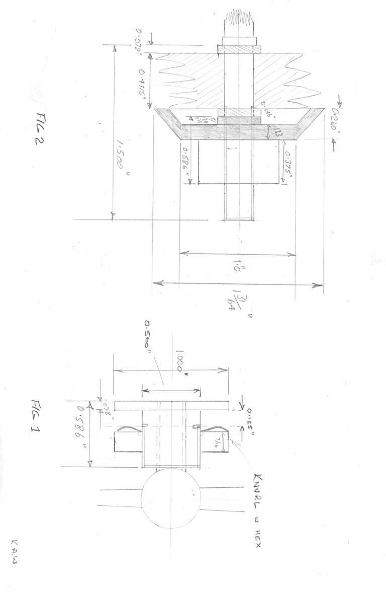
                        From my photo album (last entry) my design to modify the standard ML7 fixed dial to be able to reset them.

                        (60 year old design but works!)

                        K

                        #437380
                        KWIL
                        Participant
                          @kwil

                          Shaun,

                          To reduce/eliminate the oil fling, apart from reducing drip rate, place a suitable sized O ring on the mandrel end and touching the headstock, oil then only exits on the inside of the bearing.

                          K

                          #437508
                          Shaun Belcher
                          Participant
                            @shaunbelcher81617
                            Posted by KWIL on 15/11/2019 11:45:11:

                            Shaun,

                            To reduce/eliminate the oil fling, apart from reducing drip rate, place a suitable sized O ring on the mandrel end and touching the headstock, oil then only exits on the inside of the bearing.

                            K

                            OK, ill take a look at that when i disassemble it.

                            I think it was the drip rate that was most of the problem, but looks like some oil is still getting past.

                            Would a worn bearing be a cause of this problem?

                            Im still trying to work out how much if any wear there is on the bearings, will probably need a dial indicator to check this.

                            Thanks for that drawing, I never realised the stock dials were not resettable.

                            Im assuming someone may have made a similar mod to mine, but ill take a good look when i strip all this down.

                            #437519
                            Shaun Belcher
                            Participant
                              @shaunbelcher81617

                              Just pulled off the topslide.

                              Surprisingly the feedscrew looks OK, compared to the one on the crossslide which has significant wear to the threads.

                              The threaded nut on the topslide looks badly worn though.

                              I believe these are made from an alloy that is designed to wear out before the feedscrew does.

                              Anyway, I cant figure out how the handle and dial is removed.

                              Ive tried putting the spanner on it and it locks up no matter what direction i turn.

                              I think the last owner must have added the washers so that it has thread to catch on the feedscrew nut when its wound in all the way, as part of the thread on the outside is missing entirely.

                              Will probably leave it for now until i get the spare parts.

                              Does anyone know if this leadscrew threaded rod is available to fabricate your own leadscrew rods?

                              Would not be too difficult to make myself a set if i can get the rod.

                              I know ive seen this kind of stuff available for building CNC mills and 3D printers, but have no idea what specification the thread is for these.

                              #437522
                              Don Cox
                              Participant
                                @doncox80133

                                If I remember correctly the handle acts as a locknut to the indicator dial, both of them being threaded. The best tactic might be to undo the two cap headed screws, grip the threaded section of the screw in the vice soft jaws and attack it that way.

                                You might be interested to know that ML8 wood lathes were often supplied with a metal lathe conversion, consisting of cross and topsides, which in my experience, have had very little use. I bought an ML8 and the seller gave me a brand new one, still coated in thick grease, as an after thought just as I was leaving. They occasionally appear on eBay from time to time.

                                #437532
                                Hopper
                                Participant
                                  @hopper

                                  YOu hold the dial with a spanner on the two flats. Then turn the ball handle anti clockwise so it loosens off. Then you hold the feedscrew still and tighten the dial until end float is taken up. Then you screw the ball handle clockwise until it locks the dial in position.

                                  Given your beginner level of mechanical experience, you should hold off from disassembling your lathe any more than is absolutely necessary to get it running. It is not a beginner project to put it back together correctly from scratch.

                                  Yes you can get lengths of feed screw blank. It is an Acme thread. 10 TPI. Diameter, I forget but you can measure that.

                                  If you want to convert to metric, you will need instead to buy lengths of metric trapezoidal threaded bar. Pitch I THINK wouild be 1mm But check that with someone who has a metric Myford lathe. So long since I worked in metric I don't remember.

                                  You might find some metric trapezoidal threaded rod on eBay, Aliexpress etc. Otherwise there are several suppliers in the UK who have been mentioned on the forum before so a bit of searching around past threads should find them. But you will need to be able to use a lathe to turn the ends down and thread them to suit the dials and handles etc.

                                  Another old trick is to cut the threaded section off the feedsrew and turn it around and reattach using a spigot etc so the unworn section of the feedscrew is now in the high-use zone. Probably more effort than it is worth these days.

                                  Oil splatter from these lathes is not a problem. It's normal. That's the way they did things back then. It does not indicate anything wrong with the bearings. OIl will come out of a brand new bearing because there is always clearance between shaft and bearing — to let oil flow through! A strip of rag tied around the gap between chuck backplate and the headstock bearing will stop most of the "fling". And don't stand in front of the chuck. Work standing in front of the carriage or even a bit further toward the tailstock. Keeps you out of the hot swarf zone somewhat too.

                                  To test the bearings, hold a length of solid bar or pipe in the chuck, about a foot (30cm for you metric types) long. Grip the end of the bar and try to move it up and down and side to side. Measure the amount of movement of the spindle right at the headstock with a dial indicator. Or if you have no dial indicator you might get a rough idea by holding a finger on the spindle and bearing and feeling for movement.  Should be about one thou (two or three hundredths of a mm) of movement. IE only just discernible by feel and that's all.

                                  Edited By Hopper on 16/11/2019 10:51:29

                                  #437559
                                  Howard Lewis
                                  Participant
                                    @howardlewis46836

                                    To have a running fit the bearing has to have clearance, and oil will make it's way through, unless oil seals are fitted, which the ML7 does not have, from memory.

                                    I would have expected Myford to be able to supply new feedscrews and nuts.

                                    Once you depart from the original Left hand thread spec, you will be on your own for replacement leadscrew nuts.

                                    And the "new" leadscrew will have to be modified to take the dial and ball handle.

                                    For what my advice is worth, replace with Original Equipment leadscrew and nut, (Whether Imperial or Metric ) and save yourself (and the next owner ) a load of complication in the future.

                                    In my view, unless you are prepared to convert ALL the leadscrews and Dials to Metric, you would be better to stick with whatever spec is there. A "bastard" hybrid machine will be a P I T A to you., especially a relative beginner. It will be neither fish nor fowl (except to use, with the W replaced by a U )

                                    Think about setting a turning cut in mm, to produce a shoulder to an Imperial length!.

                                    Howard

                                    #437773
                                    Shaun Belcher
                                    Participant
                                      @shaunbelcher81617
                                      Posted by Hopper on 16/11/2019 10:44:24:

                                      YOu hold the dial with a spanner on the two flats. Then turn the ball handle anti clockwise so it loosens off. Then you hold the feedscrew still and tighten the dial until end float is taken up. Then you screw the ball handle clockwise until it locks the dial in position.

                                      Given your beginner level of mechanical experience, you should hold off from disassembling your lathe any more than is absolutely necessary to get it running. It is not a beginner project to put it back together correctly from scratch.

                                      Yes you can get lengths of feed screw blank. It is an Acme thread. 10 TPI. Diameter, I forget but you can measure that.

                                      If you want to convert to metric, you will need instead to buy lengths of metric trapezoidal threaded bar. Pitch I THINK wouild be 1mm But check that with someone who has a metric Myford lathe. So long since I worked in metric I don't remember.

                                      You might find some metric trapezoidal threaded rod on eBay, Aliexpress etc. Otherwise there are several suppliers in the UK who have been mentioned on the forum before so a bit of searching around past threads should find them. But you will need to be able to use a lathe to turn the ends down and thread them to suit the dials and handles etc.

                                      Another old trick is to cut the threaded section off the feedsrew and turn it around and reattach using a spigot etc so the unworn section of the feedscrew is now in the high-use zone. Probably more effort than it is worth these days.

                                      Oil splatter from these lathes is not a problem. It's normal. That's the way they did things back then. It does not indicate anything wrong with the bearings. OIl will come out of a brand new bearing because there is always clearance between shaft and bearing — to let oil flow through! A strip of rag tied around the gap between chuck backplate and the headstock bearing will stop most of the "fling". And don't stand in front of the chuck. Work standing in front of the carriage or even a bit further toward the tailstock. Keeps you out of the hot swarf zone somewhat too.

                                      To test the bearings, hold a length of solid bar or pipe in the chuck, about a foot (30cm for you metric types) long. Grip the end of the bar and try to move it up and down and side to side. Measure the amount of movement of the spindle right at the headstock with a dial indicator. Or if you have no dial indicator you might get a rough idea by holding a finger on the spindle and bearing and feeling for movement. Should be about one thou (two or three hundredths of a mm) of movement. IE only just discernible by feel and that's all.

                                      Edited By Hopper on 16/11/2019 10:51:29

                                      Its all good, I think I was just being overly cautious. The handle was just on too tight. I managed to unscrew it easily enough and take a better look.

                                      Just as i guessed, the washers were added to pull back more thread to catch all the way down since half the thread on the nut is missing and the unthreaded part at the end of the feedscrew would not catch.

                                      Im going to have to rebuild both slides as a minimum.

                                      It seems to be the most need of attention to make the lathe usable.

                                      Good news is that I think the rest of the lathe is in fairly good condition for its age, does not seem to be heavy wear on the bed and minimal wear on the bearing from what I can tell.

                                      Oil splatter, thats good to know its normal, yes where i stand it does not hit me, but it leaves a trail on the walls and floor so I want to address this if possible.

                                      Have made a few cuts on bronze stock and even in the poor state of the lathe, currently things seem to measure up OK.

                                      Right now the lathe is not very usable until i sort out the slides anyway.

                                      Will do the test with a dial indicator to check the bearing wear as you suggest.

                                      Was looking on myford site and yes the imperial leadscrew is 10TPI 3/8 diameter.

                                      the metric feedscrew is quoted as Threaed 3/8" x 2mm pitch

                                      I may just ordering everything from myford, but ive got a friend who can probably machine these easily enough for me which would be useful.

                                      One other question, is with the apron assembly, are you supposed to lock down the power feed lever to stop it moving when making cuts?

                                      I find the saddle will move across the bed if making an end cut with the top slide as I move the cutting tool into the stock. I found locking down the powerfeed lever would help, although i question whether or not it might need tightening up?

                                      #437774
                                      Pete Rimmer
                                      Participant
                                        @peterimmer30576
                                        Posted by Shaun Belcher on 17/11/2019 23:49:58:

                                        One other question, is with the apron assembly, are you supposed to lock down the power feed lever to stop it moving when making cuts?

                                        I find the saddle will move across the bed if making an end cut with the top slide as I move the cutting tool into the stock. I found locking down the powerfeed lever would help, although i question whether or not it might need tightening up?

                                        I take it you are disengaging the tumbler and locking the half-nuts? That's very poor practice. Use the saddle lock if you need to keep it from creeping during facing cuts, though you should be able to face without the saddle moving.

                                        #437776
                                        Shaun Belcher
                                        Participant
                                          @shaunbelcher81617
                                          Posted by Pete Rimmer on 18/11/2019 00:29:53:

                                          Posted by Shaun Belcher on 17/11/2019 23:49:58:

                                          One other question, is with the apron assembly, are you supposed to lock down the power feed lever to stop it moving when making cuts?

                                          I find the saddle will move across the bed if making an end cut with the top slide as I move the cutting tool into the stock. I found locking down the powerfeed lever would help, although i question whether or not it might need tightening up?

                                          I take it you are disengaging the tumbler and locking the half-nuts? That's very poor practice. Use the saddle lock if you need to keep it from creeping during facing cuts, though you should be able to face without the saddle moving.

                                          I did not know these had a saddle lock. I dont see any other levers on the saddle to lock it, I assumed that was the function of the power feed lever to lock it on the leadscrew.

                                          The tumbler would be disengaged with the selector lever would it not?

                                          I am not sure what you mean about locking the half nuts sorry, i just make sure leadscrew is disengaged and I engaged the powerfeed lever, which I assumed was how you locked it.

                                          The topslide also creeps a bit when cutting, this is probably a worse issue TBH. I was not able to face off a part square without holding the topslide handle firm either, hence why this is the main area of attention for me currently.

                                          The saddle seems to creep more if i was cutting directly on the face rather than facing off a part using the crossside.

                                          #437778
                                          Hopper
                                          Participant
                                            @hopper

                                            You really need to get a copy of this: LINK

                                            and this: link

                                            to familiarise yourself with the basics on the machine.

                                            #437783
                                            ianj
                                            Participant
                                              @ians


                                                                                      Saddle lock:

                                              myford saddle lock.jpg

                                              Edited By ian j on 18/11/2019 08:16:30

                                              #437794
                                              Shaun Belcher
                                              Participant
                                                @shaunbelcher81617

                                                Thanks, ill check those books out.

                                                I was assuming there would be a lever. Completley overlooked that bolt.

                                                It seems pretty tight when I put a spanner to it.

                                                Will leave some CRC soaking on it to see if it helps free it up.

                                                I see there is a mod available with a lever, I think thats a good idea rather than needing to use a spanner every time.

                                                #440746
                                                Derek Johnson
                                                Participant
                                                  @derekjohnson58813

                                                  Shaun

                                                  Oil Leakage from ML7 bearings

                                                  About 40 years ago I think I saw an article/letter in Model Engineer that utilised a ring arrgt with internal groove pressed on to the ML7 spindle just behind the chuck that collected the oil while the lathe was running. The ring arrgt has clearance to the machined outside diameter of the bearing. When the lathe stopped the oil drained down to bottom of internal groove with the excess draining to the the lathe drip tray. I think this was based on a design for overhead flatbelt line shafting bearings about 1830 (but my memory may be failing!)

                                                  For my ML7 I installed this system over 30 years ago with every satisfaction – no oil on the lab coat!

                                                  My apologies for the lack of a drawing I have forgotten the details of the arrangement. If I take ring off to measure it will destroy the ring.

                                                  Is there any one who has a comprehensive collection of Model Engineer magazines who could find the original article or letter?

                                                  Hope this helps

                                                  Regards

                                                  Derek

                                                  #440756
                                                  ega
                                                  Participant
                                                    @ega
                                                  Viewing 24 posts - 51 through 74 (of 74 total)
                                                  • Please log in to reply to this topic. Registering is free and easy using the links on the menu at the top of this page.

                                                  Advert

                                                  Latest Replies

                                                  Home Forums Beginners questions Topics

                                                  Viewing 25 topics - 1 through 25 (of 25 total)
                                                  Viewing 25 topics - 1 through 25 (of 25 total)

                                                  View full reply list.

                                                  Advert

                                                  Newsletter Sign-up