This post shows what I did to add a stepper motor indexed drive to an EMCO 150mm Rotary table, and how I added a 'Grip-True' style adjustment to the attachable 125mm 3-Jaw and 5C chucks.
I have never had a need for this device, but one thing led to another..
From the various ELS systems I did for my and other's lathes, grew a gear hobber software suite, even though I do not have or own a Hobber…Then someone else became keen to be part of the project, and so my good Wife again did all the software and is now nagging me for a test-bed..And so it starts..
I decided to follow MichaelG's route of using a rotary table as the gear blank active axis, and began modifying my rotary table. The main reason for the test bed requirement is that it is very difficult to test the software in simulation as far as accelerations are concerned.
This is an issue when doing continuous hobbing, as the blank has to spin up synchronised to the hob, when starting and stopping the hob spindle. If the inertial mass and friction exceeds the steppers capability, steps are lost and sync as well, with gear teeth misaligned. Some electronic hobbers have very little blank holder inertial mass to spin, while using a rotary table is probably the most mass you could apply..
So we will see what happens!
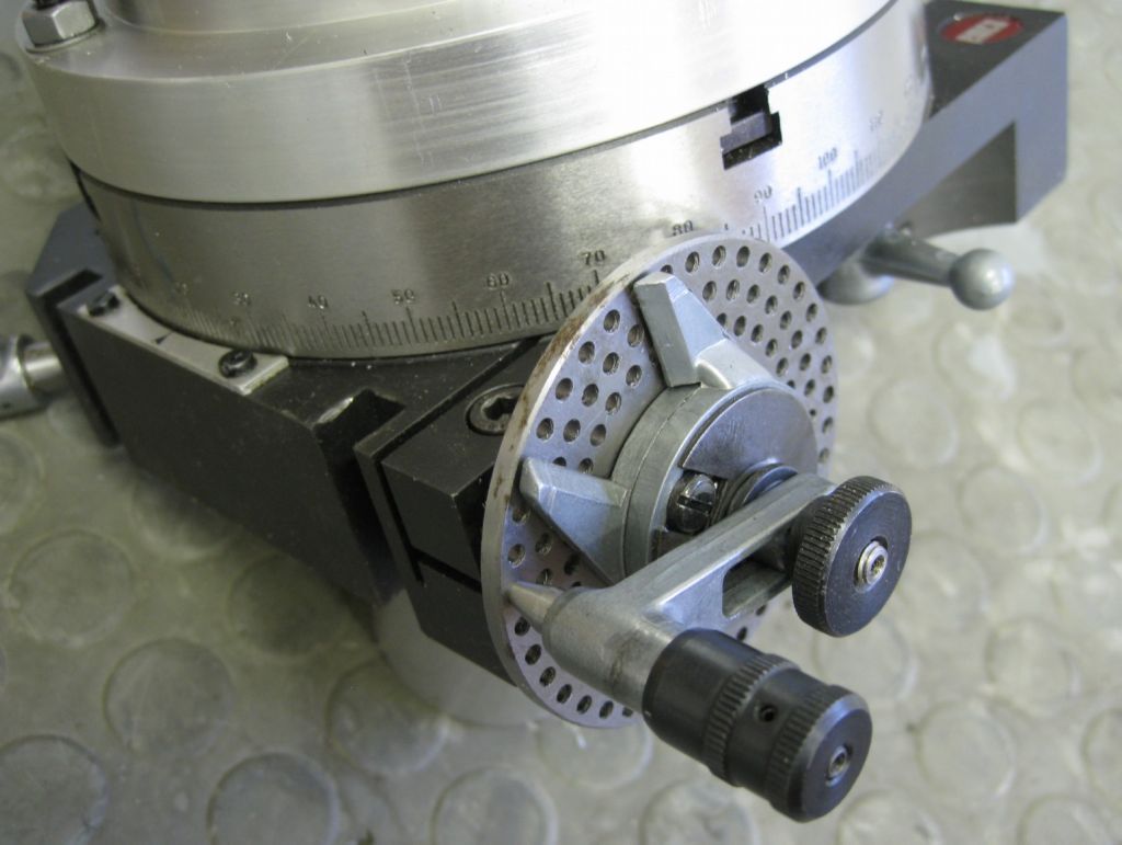
This is a view of the stock table, with index disc etc.

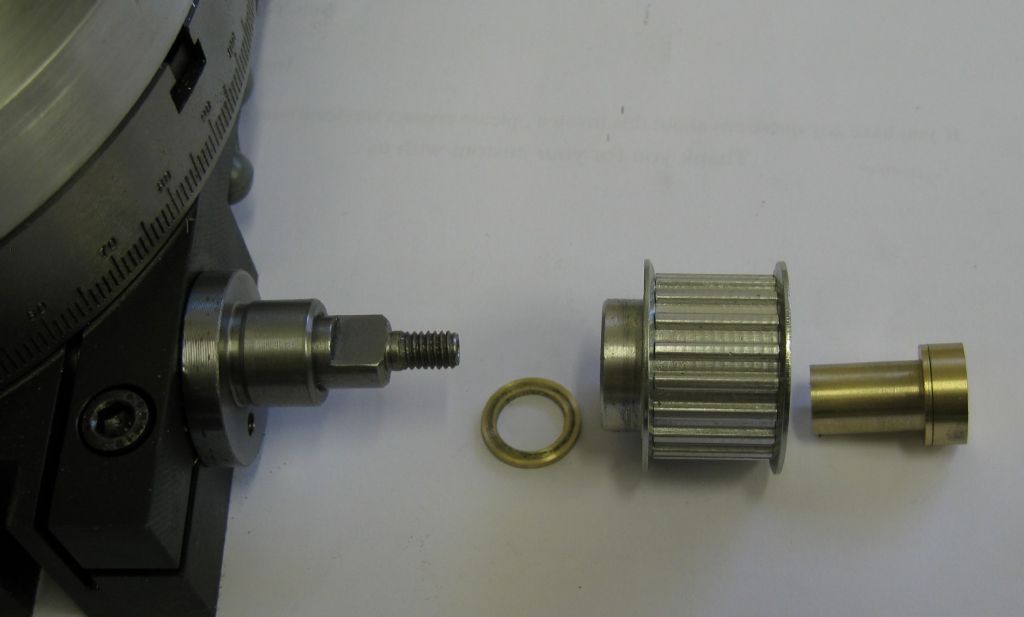
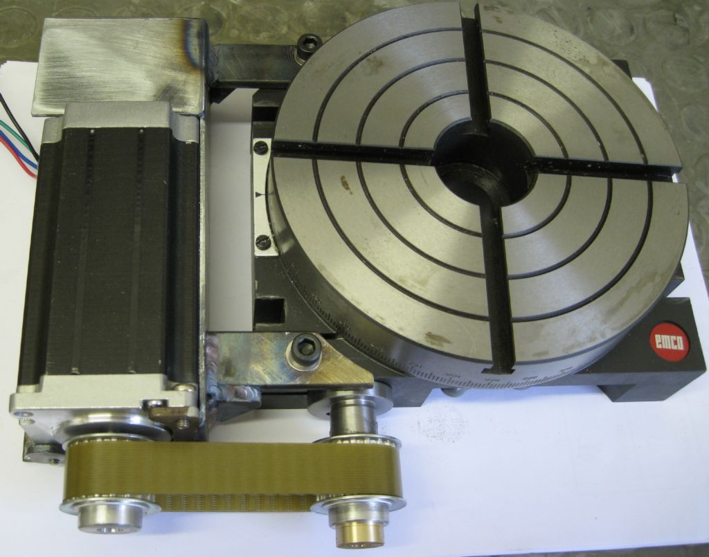
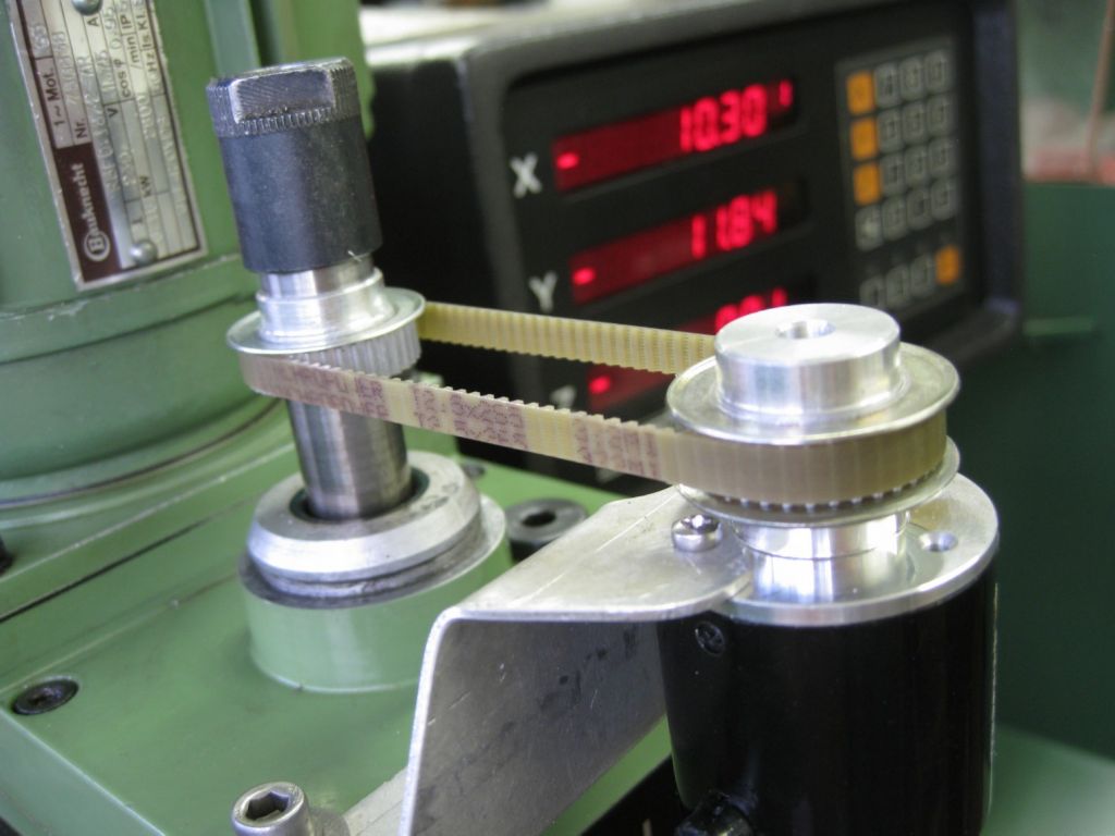
The Worm stub external to the table is short and of not a very practical shape to attach the stepper – I decide to go for belt drive as even with a NEMA23 stepper, if the stepper shaft were aligned with the worm drive, the stepper body would protrude about 16mm below the underside of the table's base.
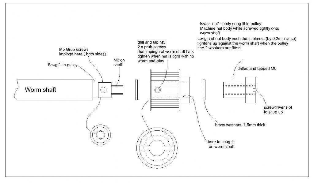
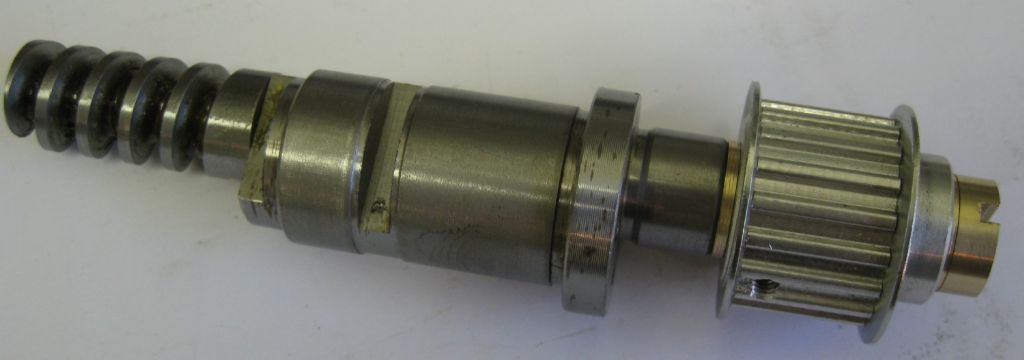
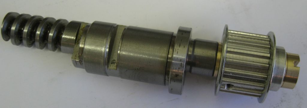
That makes it difficult when placing the table on the bench, mill table, etc – spacers are needed and so on. I made an adaptor for the pulley, which includes a shaft preload to remove worm shaft end-play.

And made attachments for the stepper to the body of the table's base.

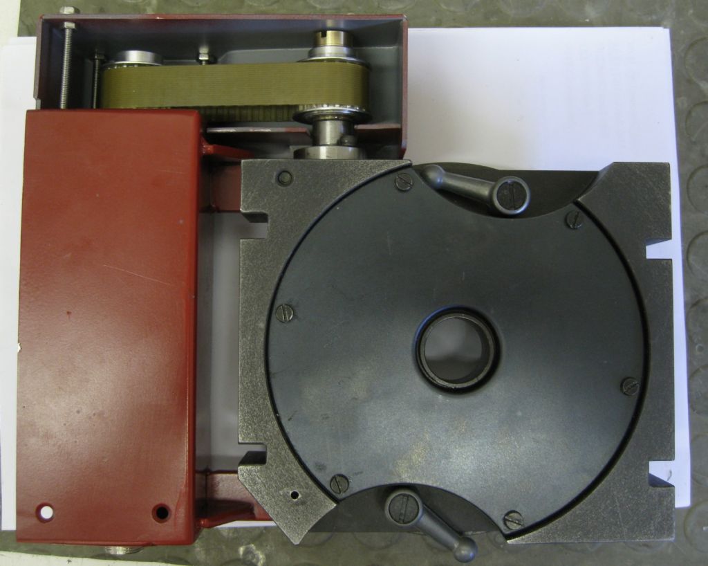
And painted it all up – view of fitment from underside.

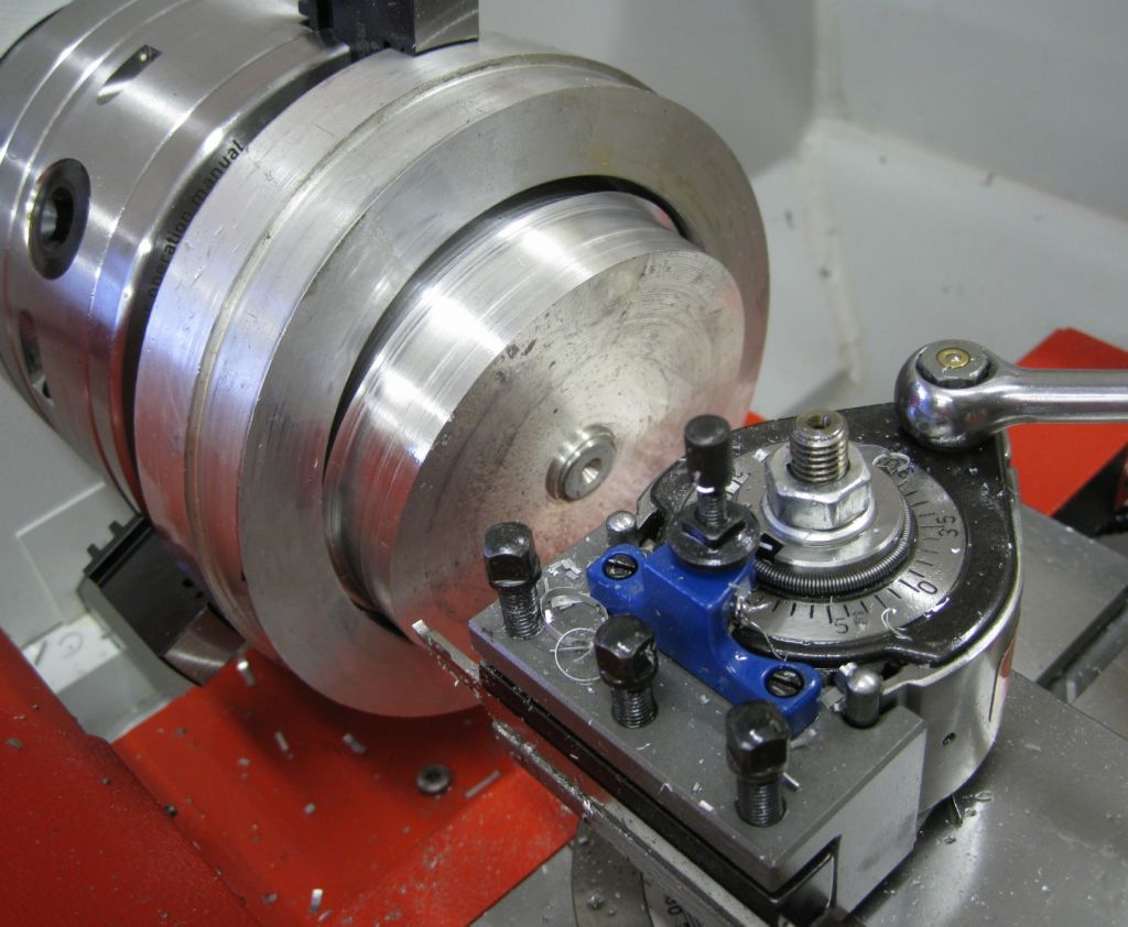
Then the Grip-True style adjustment. First the three jaw rear-bolt chuck was drilled through and recessed for cap-screws from the front, with 1mm clearance holes. Then the backplate machined to fit the chuck recess with 1mm clearance. Then a ring was made that bolts to the backplate – the chuck sits within the ring and 4 cap-screw adjusters protrude from the sides of the ring, against the outer of the chuck body, allowing centering adjustment with the chuck body bolts just nipped up.
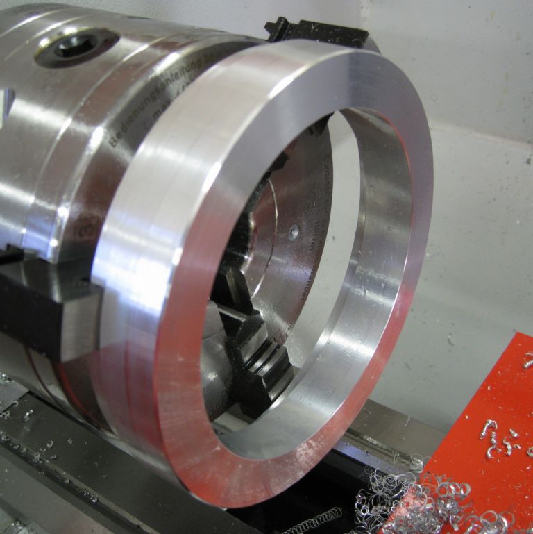
The ring is 165mm OD with the centre hole 1mm larger than the chucks ( the 3-jaw and the 5C are the same diameter body and mounting hole positions) The hole is a126mm, and the ring is 38mm thick. This was made from a large chuck of aluminium, trepanning a chunck out the center to prevent swarf from taking over workshop space.


The the ring was machined up:


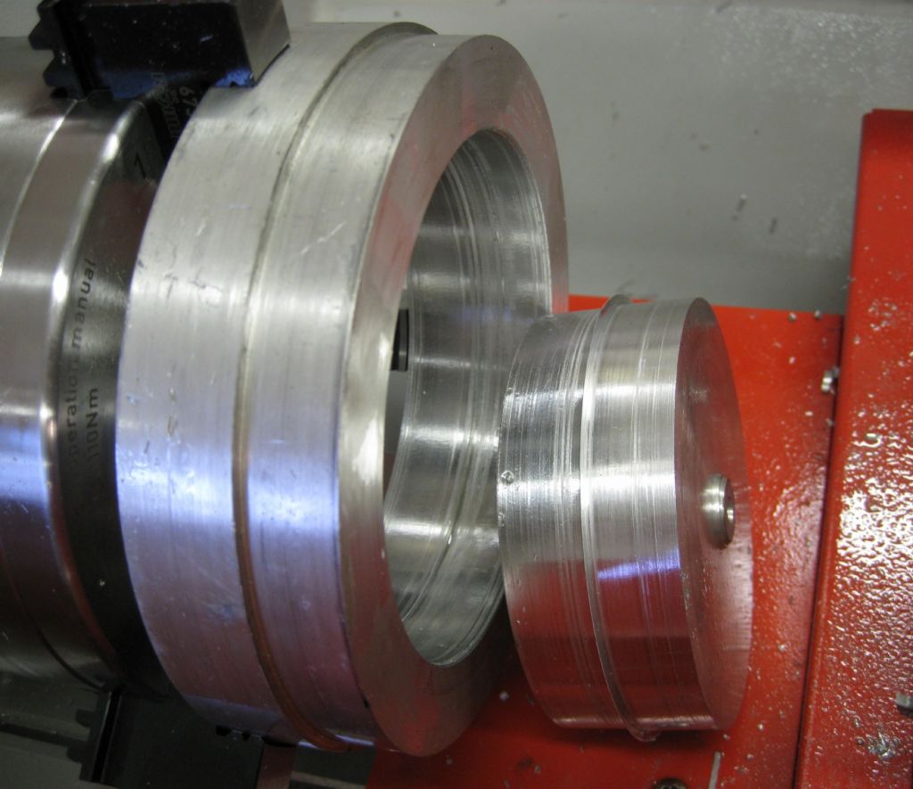
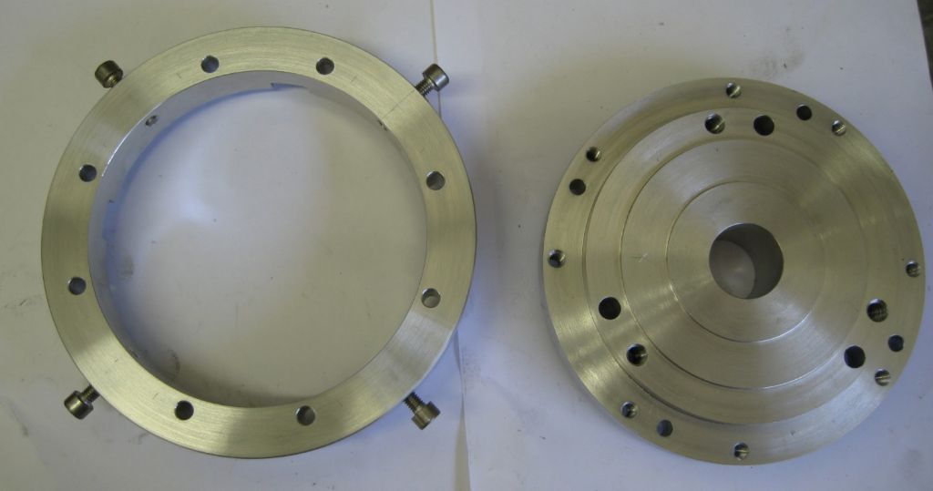
And all holes drilled – left is the ring, right the backplate

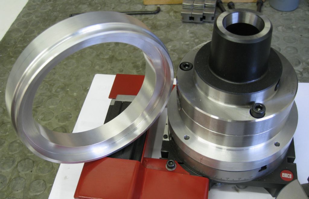
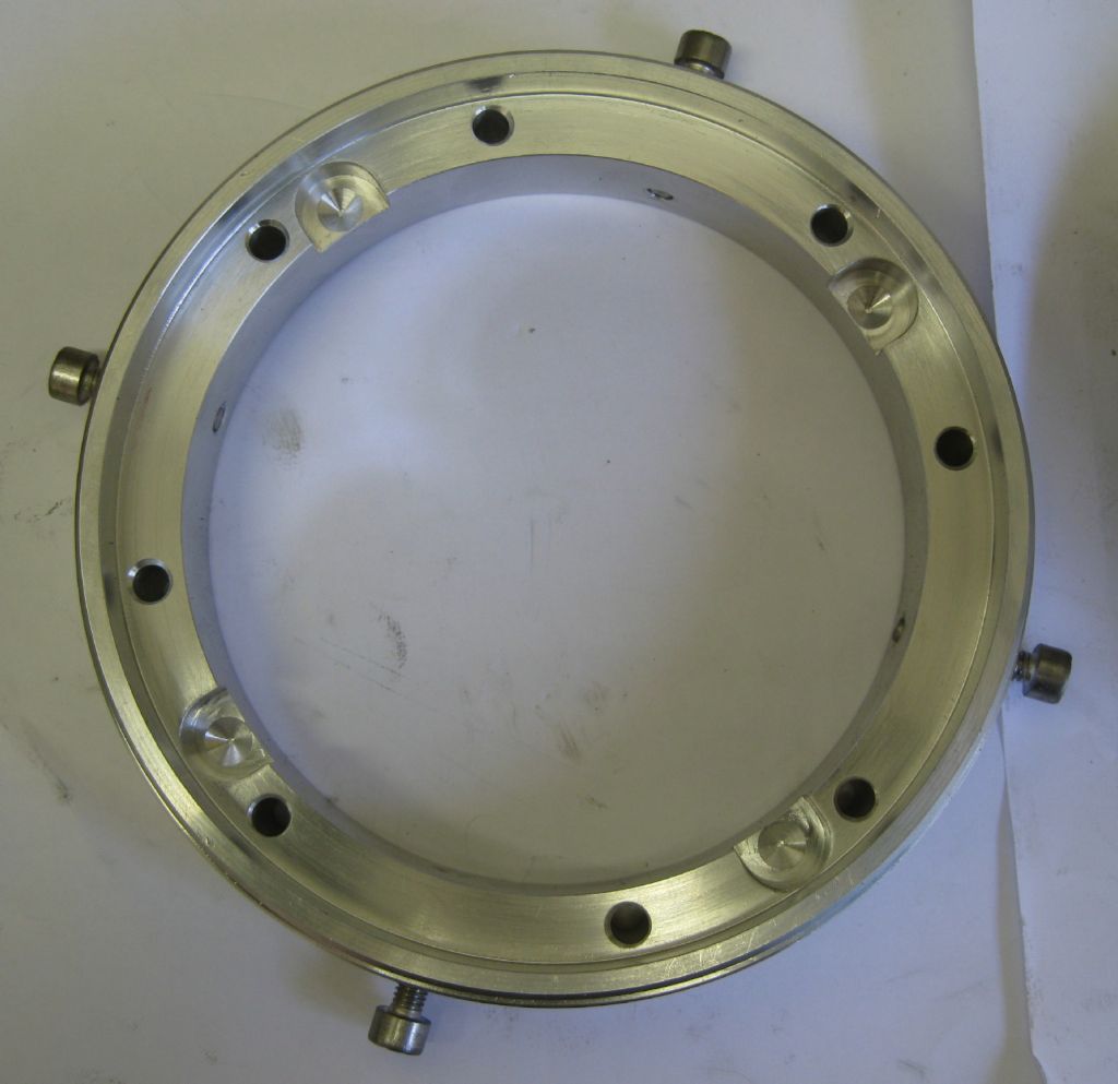
Underside of ring – the 4 relieved half-moons are to clear the backplate mounting bolts.

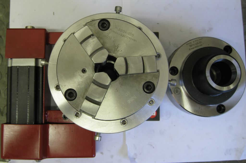
This is the table assembled with the 3-Jaw chuck fitted.

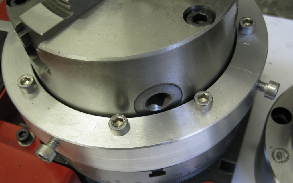
A side-ish view:

And it works a treat! very easy to set a workpiece in the chuck to 0.005mm.
Now to spin it and see what happens..
Joe
EDIT – it was an interesting juggle to get all the ring-holes in the right place-to many holes trying to be in the same places!

Zan
@zan
Well done that’s a cracking job, but that stepper! It’s huge and it could have been smaller, and still power the gear I’m wondering about converting my small dividing head to stepper control to work on my cnc and I will be using a much smaller one. That motor is bigger than on my z axis lifting all the head gubbins, but nice work keep it up. Please post again when you test it out. The results will be interesting.
Edited By Zan on 28/10/2018 15:28:48

John Haine
@johnhaine32865
Joe, that's very interesting! I'd be very interested in the software, as I am contemplating adding hobbing capability to my electronic dividing head, if it could be shared please?

Michael Gilligan
@michaelgilligan61133
Posted by Joseph Noci 1 on 28/10/2018 14:52:01:
I have never had a need for this device, but one thing led to another..
From the various ELS systems I did for my and other's lathes, grew a gear hobber software suite, even though I do not have or own a Hobber…Then someone else became keen to be part of the project, and so my good Wife again did all the software and is now nagging me for a test-bed..And so it starts..
I decided to follow MichaelG's route of using a rotary table as the gear blank active axis, and began modifying my rotary table. The main reason for the test bed requirement is that it is very difficult to test the software in simulation as far as accelerations are concerned.
[ … ]
.
Thanks for the name-check, Joe
… It looks like a wise decision on your part, to start with an actual [geared] Rotary Table:
Having started with the ungeared table, I am still struggling to find a suitable worm-gear at arealistic price 
[ seemed like a good idea at the time ]
MichaelG.

Joseph Noci 1
@josephnoci1
Thanks for the comments from all;
Zan,
I can say definitively that the stepper I have used may STILL be to small…It is a NEMA23, double stack motor, which still only gives around 1/2 the torque an NEMA34 single stack motor will give. Diameter relates directly to torque. The problem with torque requirements has nothing to do with being able to turn the table – its all to do with acceleration of the table which in my particular way of implementing the hobber is an issue. I am trying to 'exactly' simulate a mechanically geared hobber. Such a hobber will allow you to stop hobbing teeth in the middle of a job,ie, cut power to the hob spindle, and without disengaging the hob from the gear blank, simply re-apply power to the hob spindle motor. The mechanical gearing will force the blank to keep step with the hob pitch. Acceleration of the blank is mechanically linked to the hob spindle and synchronisation is always maintained.
NEMA23 is not that big? 2.3"x2.3" by about 4" long…
I am not sure this requirement is real, but it seems useful to be able to just stop, clean the teeth and have a gander to see how things are doing, and carry on where you left off?
The blank must do the same even when stepper driven, but now the stepper is driven by pulses that have a synchronised relationship to the encoder pulses from the hob spindle encoder. Typically, the hob on a 'home-hobber' will spin up from 0 to around 300RPM within 200ms to 300ms. As an example, for a MOD 0.8, 20 tooth gear, with a hob rpm of 300rpm, the blank must turn at 15rpm. Assume a typical 40:1 gearing between stepper and blank, the stepper must spin at 600RPM.
So, we need to accelerate the stepper from 0 to 600RPM within 300ms, under load, synchronised to the Hob encoder pulses, without loosing steps…With, in my case the large inertial mass on the rotary table, chuck, etc, and the friction as well. So far the math says the stepper I have used, running at 75volts in Half Step, will do the job within 450ms – difficult to mathematicate better than that, as friction coefficient is a bit of a thumb suck, so err on the high side.
For a 100 tooth gear, the stepper target rpm is only 120RPM, so much easier.
John,
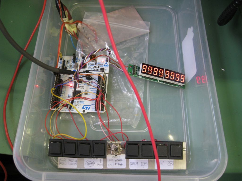
The software is free to all, however as with all these things there are complications! My implementation has buttons, encoders, jog-wheel encoders, seven segment displays and used the STM processor range and the NUCLEO STM Arduino look-alike. You would need the circuits as well to fathom what I have done, but if proficient in C, I have no doubt you could port it to the 'normal' Aduino range.
MichaelG,
I would almost suggest that you go ahead and use the worm/wheel you have and we give it a bash and see how it does! At least you could progress and maintain the interest!
Joe

Rod Ashton
@rodashton53132
Had the identical 150 Emco. Plus a stepper, driver, and Arduino Uno under the bench for ages. Waiting for its project opportunity.
Thank you for the inspiration. Go and hook it all out now.

Rod Ashton
@rodashton53132
Joseph – Could you be persuaded to share the details of your pre-load pulley/spindle adaptor please.

Joseph Noci 1
@josephnoci1
Rod, I can try – maybe better to send you some PDF sketches since image resolution in the post is poor – but here it is …

And the assembled shaft again:

Hope it helps…If short, let me know and I will describe it more
Joe

Joseph Noci 1
@josephnoci1
Well, I got the table done, the software ready to test, the electronics all hashed together and dumped in a plastic tray, so off to the workshop..
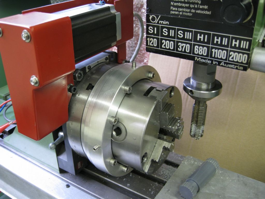
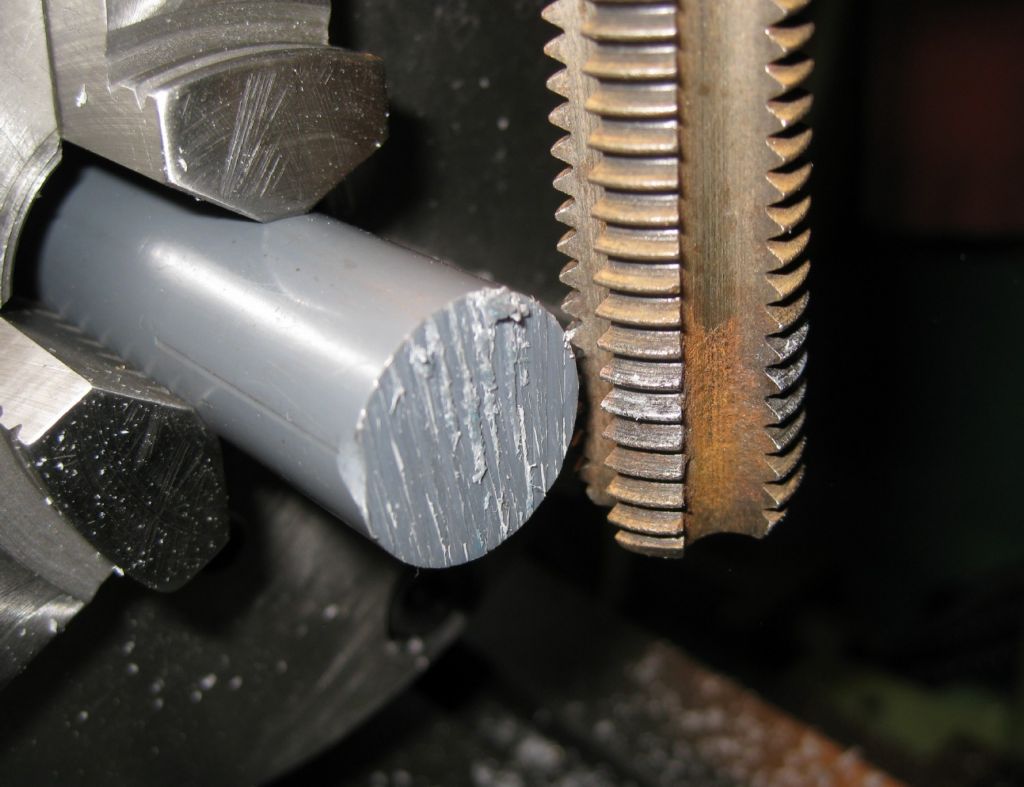
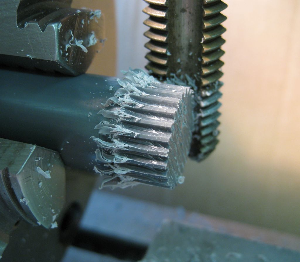
Mounted the rotary table on the angle plate, and that on the EMCO FP2 mill table, with a piece of 20mm diameter PVC in the centered chuck. As mentioned previously, I have no need for gear cutting with what I hobby about, so this is all a bit of mind-messing. So, to test I need a hob and the closet I have is a Big British Tap – a 3/4 Whitworth tap. This has 10 TPI, so 2.54mm pitch. That puts near enough 24 teeth ( on the pitch circle) around the 20mm plastic rod. And so off we go…

A VERY Blunt TAP – did not cut so much as bludgeon the material out the way…


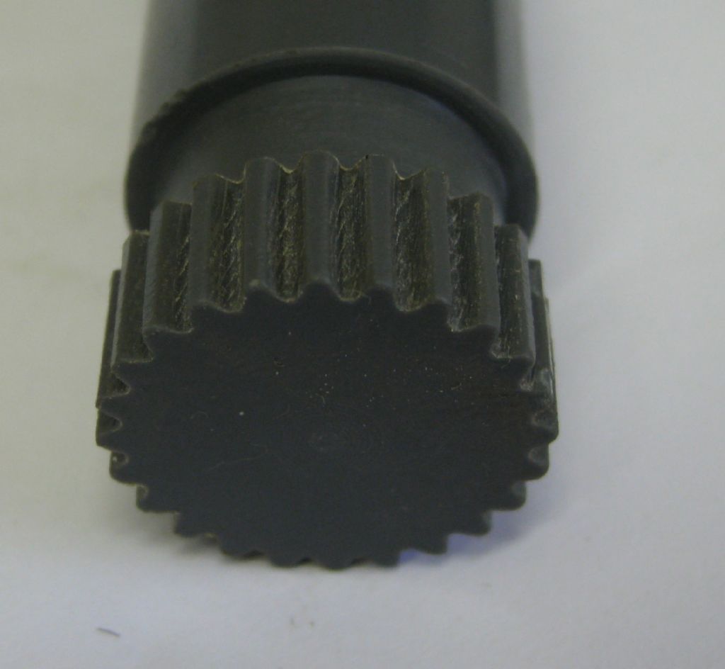
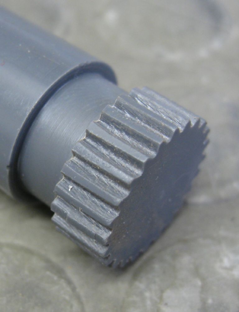
The 'cleaned' up 'gear'
valleys are very rough – As I said , the 'hob' is terrible..

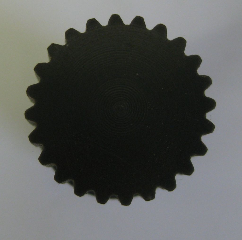
Further views of gear: End-on


The temporary mount of the spindle rotary encoder

The electronics in crude test format..

And a video of it working – not great, but neither is the hob…
So the software seems to work well but some more work is needed on the stepper side – The stepper torque is, as expected, a little on the low side for the smaller diameter gears, with hob speeds greater than 250RPM. At 300 RPM the stepper stalls, albeit at 30VDC supply voltage – I need to push the supply up to 50V, or maybe even 70volts and hope that helps. The NEMA23 stepper is a little small..
The software will now be cleaned up, and some diagnostic modes added, and then it is ready for the chaps working on this project with me..
Those of you who did not fall asleep while watching may have noticed that I have no angular shift between hob and blank, ie, the rotary table is not tilted to the helix angle of the hob – Was to much effort for just a trial run!
Joe

Rod Ashton
@rodashton53132
Reading and watching. Thanks Joe.

Rod Ashton
@rodashton53132
Erm! Joe. how does the worm drive come out of the casting please??

Joseph Noci 1
@josephnoci1
Hi Rod,
looking at the first picture in my post, right on top-
Half hidden behind the index disc, at the 10 o'clock position, is an M6 Cap screw. Loosen that up so it is slack. That clamps the worm in place.
Then next to that cap screw is the square slot cut into the casting side – where the base mounting bolt goes through into the T slot of the table you mount onto –
Inside that slot, near the bottom of the slot is a hole inside of which is a slotted head set screw- that is used to set the end stop on the worm body when you rotate the worm body to eliminate play between the worm and worm wheel.
Loosen that screw out 8 or so turns. Then rotate the worm body anticlock and pull it out the casting. You will see where the set screw impinges within a slot in the worm body. You can see the slot in the larger body diameter here, toward the worm end of the body.

let me know if you do not manage.
Joe
Edited By Joseph Noci 1 on 01/11/2018 12:05:46

Rod Ashton
@rodashton53132
Life saver Joe. It was perfectly camouflaged with crud. Now out and polished. The need for your backlash nut makes becomes apparent.
Thanks for your help
Rod

Matt Boland
@mattboland50412
Were there any issues with worm backlash with this project? I'm looking at doing a similar project with a Vertex rotary table, but was just looking at how to reduce backlash to near zero. I haven't owned a rotary table before, so I'm not sure if it may be an issue or not.

Joseph Noci 1
@josephnoci1
Backlash will remain an issue…It can be adjusted 'out' but that is not finite. The worm can be set snug up against the wheel, but absolute backlash depended on many factors here. The worm must not move axially in its mount – the worm 'thread' is not perfect and nor is the worm wheel teeth. Worm wheel concentricity may not be perfect either. The result is that you may eliminate any backlash at some setting and then find the worm binds at some wheel rotation, or is loose at others. The EMCO table is very well made, but I do find the aforementioned occurring around the wheel periphery, albeit with very small backlash – maybe 5 minutes of arc or so in places
So I guess the question is ' what is near zero'…?
I use the table always in one direction only, and for hobbing always in the 'pull' direction, ie, so the wheel is also pulled against the worm by the hob 'threading' action. Hope that makes English sense.
Joe
Edited By Joseph Noci 1 on 25/02/2022 07:39:45
Joseph Noci 1.


