Electronic Artisans ELS Article

Advert

Electronic Artisans ELS Article

Home Forums Model Engineer & Workshop Electronic Artisans ELS Article

Viewing 25 posts - 51 through 75 (of 102 total)
  • Author
    Posts
  • #231913
    John Stevenson 1
    Participant
      @johnstevenson1
      Posted by Michael Gilligan on 27/03/2016 08:54:27:

      I particularly like his starting-point:

      [quote] To do this I had to start with a sufficiently large pulse count per revolution of the spindle – in the case of my equipment, 8000 pulses per spindle revolution. [/quote]

      … I think that thread should prove to be genuinely educational.

      MichaelG.

      Edited By Michael Gilligan on 27/03/2016 08:56:49

      Michael,

      I can see where he's coming from with the high count.

      The principle is pretty simplistic and is just an electronic system of gearing where one ratio uses the full count even if sub divided by a reduction head or micro stepping and then subsequent ratios are further divided from that.

      If you don't start high enough you run out of pulses at the higher divisions.

      When I built my Electronic Hobbing machine I worked closely with Brian Thompson on this who published his results in MEW 108.

      We started off at 4,000 counts, in my case it was a standard 1024 encoder geared up 125:32

      It then went thru a divide by chip with thumb wheels setting the number of teeth needed. It worked and worked well, I have no idea how many gears were cut with this as it stood but it literally had to be in the thousands.

      It was virtually the same as an ELS and could have been made as such with a few mods to overcome design flaws.

      Because it used only one channel of the encoder and no index it could only count one way irrespective of the way the hob was running. Turn the hob forward and the blank moved forward, turn the hob back and the blank still moved forward.

      This meant every gear had to be done in one pass as a second cut couldn't be guaranteed to follow the previous pass. In my case this wasn't a problem as the machine doing the cutting, a modified Victoria U2 was more than man enough for gears with of DP of 16 and upwards.

      When after quite a few years it started to give problems then the move to LinuxCNC was already in the wings and hardware and experts lined up ready and waiting.

      If I wanted an ELS today what I would do is get the hardware which is basically a power supply, stepper driver and motor and a multi line encoder and a small board called a BeagleBone Black which is similar to a Raspberry Pi but more capable and runs Linux.

      I would then find and pay a guru to make this all work as I realise my limitations.

      It worked for me on the gear hobber. I can now cut course DP gears with as many passes as I require.

      It's also working for me on another project I don't want to mention at this point with another Linux guru who has a different area of expertise.

      The secret in these projects though is WANTING to do them, not just being interested because there are people on the various forums all too willing to detract you.

      On the Mach3 forum, when mach3 was being evolved I lost count of the people says they could do this, do that etc etc and most never came up with the goods. This even included commercial concerns that soon realised they they either couldn't meet the target or they had bit off more than they could chew.

      These are the Dementors of forums, sucking the life blood away whilst never, ever giving anything back.

      Advert
      #231918
      John Haine
      Participant
        @johnhaine32865

        Regarding gear hobbing, has anyone applied the obvious solution of a phase locked loop to multiply up the pulse count from the spindle? The ubiquitous 4046 CMOS chip plus an external divide by N can multiply the M counts per rev up to NxM, for subsequent division by whatever ratio you need to drive the hob. In effect an electronic gear-up. Seems to me much easier than finding a high count encoder, adding quadrature combination to get x4, and then possibly adding mechanical gears. Could use a one pulse per rev Hall effect sensor and a 4096 divider, which is 2 to the power 12, to get JS' 4000 pulses per rev.

        #231927
        Michael Gilligan
        Participant
          @michaelgilligan61133
          Posted by Ajohnw on 27/03/2016 11:12:40:

          Posted by Michael Gilligan on 27/03/2016 08:54:27:

          Ajohnw,

          Perhaps I am missing some 'programmers joke' but I really do not understand your last outburst.


          Your initial comment was rather rude and pointless. Rather like your comments on Brians thread.

          The only reason I mentioned how I would go about it due to odd comments I have seen at times by people who are trying to do it. I was just pointing out that it's worth seeing what the goal posts need to be before starting.

          John

          .

          John,

          My inital comment was simply an honest reaction to your "Toys out of pram" post [which seemed totally inappropriate] … and, by the way, I am not aware of it being "rather like" any of my comments on 'Brians thread' (sic).

          … Please feel free to send me details, by PM

          MichaelG.

          Edited By Michael Gilligan on 27/03/2016 13:50:30

          #231931
          Michael Gilligan
          Participant
            @michaelgilligan61133
            Posted by John Stevenson on 27/03/2016 12:34:00:

            Michael,

            I can see where he's coming from with the high count.

            < etc. >

            .

            Thanks for the notes, John

            Yes, me too … it was not so much a revelation, as an endorsement of my own opinion.

            [ which is probably why I quoted it blush ]

            Too many of the other proposals seem to start with one pulse per rev of the headstock spindle … and surely that is is going to make hard work of everything that follows.

            MichaelG.

            Edited By Michael Gilligan on 27/03/2016 14:06:28

            #231933
            Ajohnw
            Participant
              @ajohnw51620
              Posted by John Haine on 27/03/2016 13:08:24:

              Regarding gear hobbing, has anyone applied the obvious solution of a phase locked loop to multiply up the pulse count from the spindle? The ubiquitous 4046 CMOS chip plus an external divide by N can multiply the M counts per rev up to NxM, for subsequent division by whatever ratio you need to drive the hob. In effect an electronic gear-up. Seems to me much easier than finding a high count encoder, adding quadrature combination to get x4, and then possibly adding mechanical gears. Could use a one pulse per rev Hall effect sensor and a 4096 divider, which is 2 to the power 12, to get JS' 4000 pulses per rev.

              The divider can also be set pretty easily to different ratio's. An example of that approach is the other style of els I posted a link to.

              John

              #231934
              John Stevenson 1
              Participant
                @johnstevenson1
                Posted by Michael Gilligan on 27/03/2016 14:04:20:

                Posted by John Stevenson on 27/03/2016 12:34:00:

                Michael,

                I can see where he's coming from with the high count.

                < etc. >

                .

                Thanks for the notes, John

                Yes, me too … it was not so much a revelation, as an endorsement of my own opinion.

                [ which is probably why I quoted it blush ]

                Too many of the other proposals seem to start with one pulse per rev of the headstock spindle … and surely that is is going to make hard work of everything that follows.

                MichaelG.

                Edited By Michael Gilligan on 27/03/2016 14:06:28

                .

                Precisely.

                Back in December 2008 Art added multiline encoders to Mach 3 for one version only but it was withdrawn quickly as it didn't work.

                Remember Mach 3 was always a work in progress with two versions, one an earlier one that was the production version and was the best up to that point, and a later beta version is when everything went right would replace the production version at some point.

                During this period I did a lot of development work with Art on this trying to sort the problems out. I probably spent a whole week on this virtually full time. Emails from this period prove that a lot was being done and Art worked tireless on this one, often with a new version within a few hours, no mean feat.

                My version of turn looked nothing like the standard on. It had possibly 10? extra DRO boxes that could keep count what was happening and allow me to video the screen so Art could also see.

                Art didn't have a lathe capable of heavy screwcutting at this point.

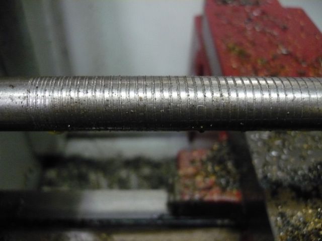
                Some photo's from that era

                This is a classic one, starts off well but the longer it goes and the more passes the bigger the lead error.

                This is all down to the single line index getting out of sync and windows not being real time, never managing to get it under control.

                It could be better, in fact the big boys with 10 HP spindle motors didn't have this problem because threading isn't a high torque operation on a CNC and if you have 1/2 a tonne of spindle and headstock gears spinning around you are not going to vary speed. But if a small lathe can thread OK so everything else will follow.

                The answer is to pass the threading instructions to an outside card but then the problems are who will invest in such a card for such a small return on capital as lathe users are well in the minority to mill uses and many are on Linux anyway.

                Mach 4 is in the same boat, in fact it's worse in that Mach 3 had the parallel port controller built in whereas Mach 4 is a dumb controller and relies on paid external support to run anything, even the parallel port.

                #231936
                Ajohnw
                Participant
                  @ajohnw51620

                  Did slip compensation and or V/F control via an inverter make any difference John?

                  It is aimed at this sort of problem but I would wonder if it's fast and accurate enough.

                  John

                  #231948
                  John Stevenson 1
                  Participant
                    @johnstevenson1

                    ??????????????

                    Sorry that makes no sense to me what so ever.

                    Can't be slippy, I'd swept up and no VFD fitted, in fact you can't fit one.

                    #231962
                    Ajohnw
                    Participant
                      @ajohnw51620

                      Whoops I assumed that you would have an inverter driving the lathes main motor. In terms of maintaining speed as the loads change inverters have improved from early days but I'm not sure if they are up to this sort of thing.

                      Should add that they can have 2 basic modes volts frequency or constant torque. VF best for varying loads and also slip control which is supposed to improve it still further.

                      John

                      Edited By Ajohnw on 27/03/2016 18:49:44

                      #231975
                      John Stevenson 1
                      Participant
                        @johnstevenson1

                        Right, with you now and this is the last thing you want.

                        One one hand you have a semi closed loop between the spindle encoder and the controller. I say semi as it relies on the one pulse per rev.


                        Then you bring in another closed loop between the spindle and the inverter but the two do not connect the loop directly.


                        What happens is spindle slows, encoder picks it up and tells controller to slow also and just as it's all happening VFD says to spindle, speed back up so it goes into a chasing it's own tail routine which just gets worse and worse until it develops into a right tank slapper.


                        Thing is there is no need for this. If the encoder has a high enough count and it's in real time, [ Linux, BBC, DOS etc ] then it just works.

                        But so far only Tormach have closed the loop in supplying a piece of software that is plug and play.

                        Which is where we came in………………………………

                        Edited By John Stevenson on 27/03/2016 19:24:23

                        #231989
                        Mark C
                        Participant
                          @markc

                          The inverter "closed loop" is independent of all other things as JS states.

                          However, on modern inverter drives (the technology being discussed is often known as "vector technology") the feedback is sensed on the drive output side (or encoder driven previously) and simply provides "tight" speed control accuracy. The speed variation would be expected to be better than 10% of a standard inverter at minimum and perhaps significantly better depending on system dynamics and physical limitations (motor size etc.).

                          Mark

                          I should have added: this can only improve matters over a non-feedback drive or plain inverter drive as your base speed will be significantly better regulated

                          Edited By Mark C on 27/03/2016 20:40:28

                          #232008
                          Anonymous

                            I'm confused, I thought vector control converted the rotating three phase vector to a quasi-stationary two dimensional vector, D and Q, via the Park-Clarke transform, and controlled the stator currents rather than direct controlling the speed? Of course if you have a speed, or rotation, sensor you can have full torque at zero speed, which is what we used for electric vehicle drives.

                            Andrew

                            #232009
                            Ajohnw
                            Participant
                              @ajohnw51620

                              That's why I mentioned it Mark. VF speed control included in vector control gives decent speed regulation with load and as consequence a more constant speed. Adding slip compensation to that and it improves things further but I have no idea by how much. The manufacturers reckon it can make the speed constant enough for some applications that couldn't use inverter speed control before.

                              The other mode they have, constant torque will give speed variations with load. I believe it's mostly intended for water pumps and things like that.

                              One of the problems with ELS's is variation in motor speed especially with a 1 line encoder but it will also cause problems compensating for with more lines. I've no idea how it worked out but I came across some one who switched to a dc motor and I assume and encoder and tried to keep the speed constant that way. It's needn't be an expensive option – just find a cheap motorised treadmill. One problem though may be the cost of good quality servo motor drivers. Just to make it more difficult these motors are generally 180v with the power ratings well overstated. There may be brushless ones about now. Not that this would help either really.

                              John

                              #232010
                              Mark C
                              Participant
                                @markc

                                Andrew, I don't know what goes on with the binary imps inside the inverter but the net result of the benefits you mention is that you also get much tighter speed control – if you ask for 100 rpm you get 100 rpm not 100 rpm ish.

                                John, I was not certain about the VF aspect. I checked the handbook for an inverter I am using that has vector capability (Durapulse). VF is listed as a basic control method. Vector control is an advanced option (although I suppose the very nature of these drives means there will be manipulation of voltage and frequency).

                                In the picture previously from JS the thread looks to show accumulated errors as he mentioned. I don't see how speed regulation is to fault here – that would cause a (random?) widening of the thread all along rather than the pitch error developing at one end?

                                Mark

                                #232014
                                John Stevenson 1
                                Participant
                                  @johnstevenson1

                                  Think we are missing the point here.

                                  Speed control shouldn't be needed.

                                  Any system that can use multi-line encoder and threads correctly does it with good software and real time.

                                  The BBC never had a closed loop vector controlled motor, neither has the Tormach or even the basic LinuxCNC

                                  We don't need no steenking smoke and mirrors wink

                                  #232015
                                  Mark C
                                  Participant
                                    @markc

                                    JS, I agree – all the binary imps need to do is put the tool point in the right place on the surface of the bar at the correct time, over and over…… how hard can it be?

                                    Mark

                                    PS. I now have a mental image of a chief imp whipping the lesser imps as the speed gets turned up more and more……..perhaps its time for bed.

                                    PPS. If you think that is hard, I am currently trying to get a HMI running a couple of control macros to co-ordinate a PLC running two motors at varying speeds to provide a formed metal part that is springy. The PLC uses both 16 and 32 bit registers. The addressing is octal, the registers are binary and the number formats are either binary, octal, hex, BCD or real with implied decimals. I still don't know if the system is big or little indian!

                                    Edited By Mark C on 28/03/2016 00:36:26

                                    #232016
                                    Ian P
                                    Participant
                                      @ianp

                                      I have been following this thread (pun not intentional) with fascination. I think I have learnt quite a bit and a lot of things I was going to ask about have been covered. However one or two things puzzle me.

                                      I could never understand how a one pulse per rev could provide enough control to achieve a constant pitch over each turn of thread (I still can't). I accept if the thread was relatively long then with the flywheel effect and the relatively constant cutter load the end result would be acceptable. What happens though if one was cutting a large diameter very short blind thread up to a shoulder . When I do this conventionally its generally at a very low spindle speed but when the cut first starts the spindle noticeably slows. That would surely wreak havoc with simple ELS?

                                      With a high count spindle encoder the above becomes irrelevant so a perfect thread could be cut every time.

                                      Even with an all singing all dancing ELS is it practical to cut say, a 4mm long internal M75x1.0 thread? (even with a runout groove)?

                                      Ian P

                                      #232027
                                      Martin Connelly
                                      Participant
                                        @martinconnelly55370

                                        Ian, the slowing down you refer to is the reason single pulse timing does not work for some people. A system using a single pulse, such as Mach3, uses the time between two pulses to calculate the rpm of the spindle. It then calculates the feed rate required for the cutting of the required thread pitch. If the spindle slows when cutting starts the system does not detect this soon enough so the pitch of the thread is longer than it should be. If your spindle kept a constant rpm whether cutting or not then a single pulse per rev will work fine. I think with Mach3 that once the travel speed is set it is not varied until the next code block which is the retract operation of the tool. That is why you get a result like the one in an earlier photo where the pitch stretches after a time as a slowly slowing spindle speed is not detected and acted on. The systems that use a multi line encoder and constantly respond to the input from the encoder should have much more accurate pitch control. I will not say perfect because there will always be some control lag but it should be so low that it is either undetectable or competely acceptable.

                                        The discussion has veered towards how good speed control can be with a vfd. This is because single pulse threading needs this good speed control and so makes either ELS or Mach3 useable for threading in more situations such as large diameters or long lengths of thread where the spindle is more likely to slow down.

                                        Martin

                                        #232028
                                        Martin Connelly
                                        Participant
                                          @martinconnelly55370

                                          Ian, I missed answering you last question. If your spindle slows when cutting the thread you describe then you would need a multi-line encoder system that responds constantly to the encoder input.

                                          Martin

                                          #232029
                                          frank brown
                                          Participant
                                            @frankbrown22225

                                            I agree with you, Ian, I reckon that from a standing start, you would need 10 turns of the thread , before the pitch would become stabilised. These ten turns would have to be removed before the thread could be used. Any change in the drag of the saddle along the ways would end up in the pitch getting finer until the spindle has pumped enough correction pulses into the system (another 10 turns of the thread?).

                                            Frank

                                            #232047
                                            Ian P
                                            Participant
                                              @ianp
                                              Posted by Martin Connelly on 28/03/2016 09:15:30:

                                              Ian, I missed answering you last question. If your spindle slows when cutting the thread you describe then you would need a multi-line encoder system that responds constantly to the encoder input.

                                              Martin

                                              I understand that completely Martin and if I was going to pursue fitting a motor driven leadscrew I would only do it with a high count spindle encoder.

                                              Whilst an ELS might be able to create every pitch of thread as well as position the cutter repeatable for every cut it seems to me the whole ELS system would be of little value unless a cutter retraction method was incorporated.

                                              Since that retraction may as well be the cross slide feedscrew one may as well call it a CNC lathe. It seems to me that the whole ELS idea was predicated on the 'answer looking for a question' principle!

                                              I assume the big difference between CNC and ELS is one of backlash?

                                              Screwcutting conventionally is always in one direction with the operator ensuring the (significant) half nut etc backlash is taken up before the cutter engages, presumably a basic ELS does the same.

                                              I did seriously consider an ELS on my current lathe (Harrison M250) whilst it can cut metric and imperial threads with its screwcutting gearbox, it frequently needs different changewheels for each pitch which rather defeats the object of the gearbox.

                                              Ian P

                                              #232064
                                              Michael Gilligan
                                              Participant
                                                @michaelgilligan61133

                                                I may be in a very small minority here, but:

                                                For my purposes [being to have full set of 'virtual' ratios available], I would like to see all reference to spindle speed taken out of the equation … i.e. the ELS should work properly when the lathe is being hand-cranked.

                                                This is particularly relevant to short threads, such as found on various optical instruments; but I suggest that it might be the purer starting point in any case.

                                                … I think this demands a high resolution encoder on the headstock spindle.

                                                MichaelG.

                                                #232070
                                                Ajohnw
                                                Participant
                                                  @ajohnw51620

                                                  I have seen comments about a very coarse pitch being cut by hand cranking just due to the pitch. This particular "project" died and the demo's had some strange aspects. He used an arduino and a relatively low count encoder so it wouldn't have worked that well hand cranking anyway. The resolution needed for that would need to be enormous and would still likely to cause problems unless it was turned very steadily. Think about maintaining a fine pitch to microns by turning a leadscrew very slowly in relationship to the spindle speed.

                                                  Gears can do that easily even if the actual pitch is slightly out the variation will be tiny.

                                                  No need anyway – providing thread length can be specified. I tried to buy a used lathe from Italy that did this by specifying pitch and the number of them which would be ideal for many pieces of work but a means of specifying long lengths would also be useful so could do the same thing. It was a modified Taiwanese / Chinese lathe by the look of it. Maybe a variation on the phase lock approach I posted earlier. It was set up via BCD switches. Maybe it used rate multipliers.

                                                  John

                                                  PS There is also a need to think about people taking a fine finishing cut.

                                                  Edited By Ajohnw on 28/03/2016 12:39:10

                                                  #232071
                                                  John Haine
                                                  Participant
                                                    @johnhaine32865

                                                    Michael,

                                                    I think that (a) this makes the problem much harder and (b) is not necessary.

                                                    With the normal CNC/ELS approach you at least try to have the work and the leadscrew turning continuously at the right speed ratio and in sync, start the tool moving at the same point for each pass, with the same acceleration profile each time. Keeping sync comes down to having enough power and inertia in the system and if possible fast sensing of the spindle position to correct the tool velocity if the spindle slows down with the cutting force. The example of Linux CNC seems to show that this can be done even though the user interface and set-up may be ghastly.

                                                    But sensing just how far you have turned the spindle by hand, and moving the leadscrew by just the right number of turns, starting it and stopping it in exact sync, when the speed range may be rather large (stationary to say a rev per second), possibly stopping very quickly when you reach a shoulder, would need a really complex servo system. But you're right, it would need a high resolution, probably absolute encoder on the spindle.

                                                    On the other hand, if you are cutting short threads to a shoulder, you can do this under power and trust the CNC to stop the feed and withdraw the tool, probably more accurately than you could by hand. I do this with Mach3, and while I accept JS' reservations about the one pulse per rev encoder and possible inaccuracies in the thread, it does work.

                                                    Just as a matter of fact, I have cut threads successfully using Mach3 on a Myford Super 7, at least quite small diameter, at the lowest non-back-geared speed which is about 200 rpm. But I am thinking about moving to LinuxCNC on the lathe at least, to get better threading. It should be perfectly feasible to use the workshop PC in dual-boot, with Windows + Mach3 for milling and possibly plain turning; and Ubuntu + Linux CNC for threading. If this is successful then maybe I'll produce an article…

                                                    #232072
                                                    Ian P
                                                    Participant
                                                      @ianp

                                                      What I have gathered so far seems to indicate that a simple (one pulse/rev) ELS would have limited practical use (from my point of view). Many of the threads I cut are short and up to a shoulder so I dont see how the ELS can hack it.

                                                      Presumably a multiline encoder would be needed for multistart threads, or are the same methods used as when conventional screwcutting?

                                                      Ian P

                                                    Viewing 25 posts - 51 through 75 (of 102 total)
                                                    • Please log in to reply to this topic. Registering is free and easy using the links on the menu at the top of this page.

                                                    Advert

                                                    Latest Replies

                                                    Viewing 25 topics - 1 through 25 (of 25 total)
                                                    Viewing 25 topics - 1 through 25 (of 25 total)

                                                    View full reply list.

                                                    Advert

                                                    Newsletter Sign-up