DRO on Rong Fu RD45

Advert

DRO on Rong Fu RD45

Home Forums Manual machine tools DRO on Rong Fu RD45

Viewing 15 posts - 26 through 40 (of 40 total)
  • Author
    Posts
  • #402038
    John Reese
    Participant
      @johnreese12848

      That is the type I propose to use on my quill.

      Advert
      #402043
      Clive Foster
      Participant
        @clivefoster55965

        John

        If funds permit its far better to use a proper glass or magnetic scale on the quill with three axis display. Given that displays with Z-axis summing are now available at similar cost to three axis ones I'd be seriously tempted to get one of those and add the extra scale for head height later.

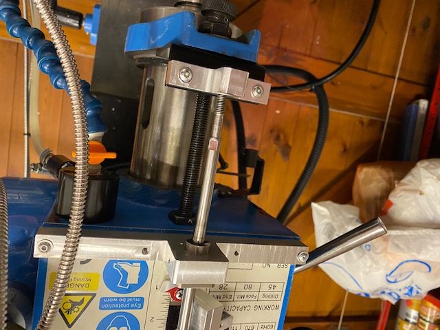
        Rong Fu style mill depth gauge systems, as shown in Pauls picture above, aren't very good. It usually comprises a vertical screw rotating more or less loosely in the quill bottom fitting driving a nut and indicator unit up and down a slot in the front faceplate. The various clearances involved make for a mushy stop and imprecise adjustment. If mine is typical getting repeatable cut depths by bringing the quill down onto the stop is pretty much impossible. Close but no cigar.

        As a temporary measure I replaced the screw with a solid rod, drilled out the nut to suit and added a wing nut headed screw to lock the drilled out nut to the rod. The indicator bar got dumped as the top edge of the nut could clearly be seen in the slot making a fine indicator against the scale. I'd intended to make an external screw type depth stop but the simple lock to a fixed rod device worked fine in practice giving a nice solid easily set stop. A Bridgeport style stop with two collars, one locking and one graduated in suitable fractions of a revolution would have been significantly better but much more work. Not worth the effort as I had a glass scale on the quill.

        Clive

        #402044
        John Reese
        Participant
          @johnreese12848

          Clive,

          I have a 3 axis DRO. I planned to use the Z axis on the head rather than the quill. After reading your post I think I should have bought a 4 axis unit.

          #402050
          Paul Lousick
          Participant
            @paullousick59116

            The RF quill stop shown above is as Clive describes, just a screw with a nut. The same as you have on a bench drill. It is not accurate and I only use it for drilling holes.

            The digital readout shown is the same type as used in digital calipers. It is just as accurate as the calipers and just as reliable (or not) as the cheaper brands. It is the same as I had on my SX3 mill. It is an inexpensive addition to the mill. ($20-$30 on ebay for a digital height gauge or $200-$300+ for glass scales)

            The glass scale (or magnetic) and displays are more accurate, reliable and have more features. I am using an Easson brand unit which calculate more than just a distance between 2 points. eg. Stores datum point when power is turned off, calculates the mid point between 2 positions, holes on a PCD, has a number of memories and can calculate the movement required in the Z-axis and the X-axis to mill a vertical curve.

            Paul.

            Edited By Paul Lousick on 25/03/2019 05:27:44

            #402072
            Clive Foster
            Participant
              @clivefoster55965

              John

              I put my glass scale on the quill because lifting the head with the short winding handle provided was such hard work that I saw no reasonable prospect of setting the height accurately and repeatably enough to justify a DRO readout. Mine was also a bit unreliable dropping down. Realistically anything better than around 1/16" or 1 mm accuracy would have been just too hard. After modifying the depth stop to a solid rod and slider my normal technique was to touch off the workpiece, zero the quill readout, move the table to put the cutter into clear air and set the stop at finish cut depth. Worked a treat. Having a hard stop was great protection against Ooops moments.

              Never got round to putting a ruler on the column for approximate head height setting before selling the machine and moving up to a Bridgeport. Put glass scales on table and knee of the Bridgeport with a pull wire sensor on the quill. Cranking the knee up for cuts is perfectly practical on the Bridgeport, nice long handle, but I still use the set stop using the readout technique on the quill if I need to go down an accurate depth. Usually drilling.

              I put my glass scale on the crowded right hand side of the head because I didn't like the idea of running the readout cable across the head. Visions of things getting seriously hooked up if I tilted the head. With a moving readout head you need to arrange some form of cable guidance. I just used a 2 or 3 inch long plastic bush rattle clearance on the cable at the head end and arranged a clamp close to the DRO box to hold it in an inverted U loop. The flexible metal sheath was stiff enough to hold the U. Had to remember to undo the clamp before tilting the head. Which happened about once a year. The readout cables were way longer than needed so I rolled the spare up into loops around 10 inches across with cable ties to hold them and hung them off a hook fitted to the back of the column.

              Clive

              #402099
              John Reese
              Participant
                @johnreese12848

                Clive,

                If I can crank up the knee of a Bridgeport I should have no problem cranking the head of my mill up or down. I planned to use head movement in the same manner I used knee movement on the Bridgeport. I will tell you later how successful it was. If my idea does not work out I can buy a short scale and fit it to the quill.

                #402163
                Jon
                Participant
                  @jon
                  Posted by John Hinkley on 24/03/2019 10:17:48:

                  John (Reese),

                  You don't HAVE to either lose Y-axis travel or access to the X-axis travel stops when mounting a DRO scale on the X-axis.

                  Where or how would you be able to mount a rotary table with dividing plates?
                  Impossible.

                  Also power feed stops and switch?

                  #402167
                  Jon
                  Participant
                    @jon
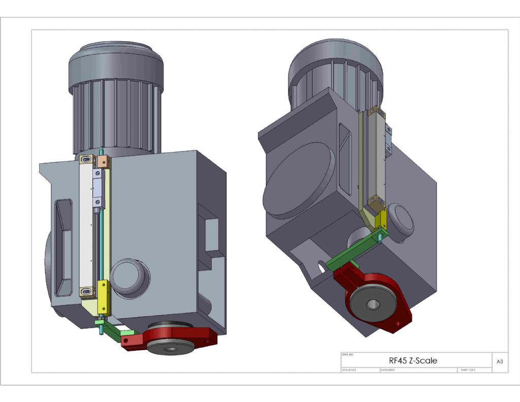
                    Posted by Paul Lousick on 24/03/2019 00:13:45:rf45  z-scale sht 1.jpg

                    Top tip beef up the green extention.
                    As a guide mine is hell of a lot stiffer and the instances where vibration or intermittant cutting is apparent, mine can continually or just jump on the readout. ie continually count up. or take a drilling cut to zero on dro and find its stating 290mm to go. Had it last week boring a hole heavy cut and boring head opened up larger, only 960 to go by 5th April.

                    #476512
                    Robert Butler
                    Participant
                      @robertbutler92161

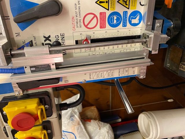
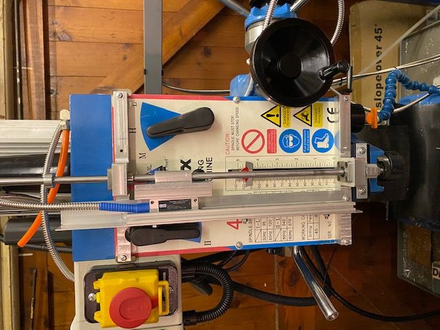
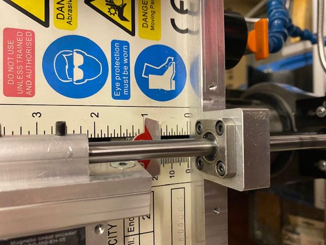
                      I have finally! (just) completed making the the parts and installed the magnetic DRO to the Z axis of my Chester Super Lux milling machine. Why is it the warranty always expires long before the components come into use. The installation comprises two alloy mounting brackets carrying two 8 mm linear bearings with an 8 mm shaft to which the the encoder is fitted using a machined alloy adaptor. The magnetic scale carrier is mounted between the two mounting brackets with provision for adjustment. An alloy carrier is fixed to the quill shoe via a 90 deg.folded steel bracket all works well and now I only need to look at one console when setting up.

                      The advantage of this design is the lack of slop in the encoder travel and no overhanging structures introducing inaccuracies in the z axis reading. The quill return spring acts sharply.

                      I am indebted to various forum members for inspiration along the way.

                      I will attempt to make a separate posting with the relevant images.

                      Robert Butler

                      Edited By Robert Butler on 31/05/2020 22:08:10

                      #476523
                      Robert Butler
                      Participant
                        @robertbutler92161

                        img_0185.jpgimg_0182.jpgimg_0181.jpgImages at whatever orientation the system permits!!!img_0178.jpg

                        The website rotates the photos randomly even though they are all in one orientation from my pictures folder.

                        Robert Butler

                        Edited By JasonB on 01/06/2020 07:32:17

                        #476536
                        Robert Butler
                        Participant
                          @robertbutler92161

                          Dear Neil/Jason is it possible to correct the orientation of my images for this posting please. Robert Butler

                          #476543
                          Paul Lousick
                          Participant
                            @paullousick59116

                            Hi Robert,

                            The photos appear sideways because they were taken vertically. Some smart photo software can sense this and automatically rotate the photo for viewing but it does not actually rotate the original image. You have to use photo editing software to do this before you upload to MEW.

                            Try useing Windows explorer or other software to view them in their native orientation.

                            Paul.

                            Edited By Paul Lousick on 31/05/2020 23:51:51

                            #476545
                            Robert Butler
                            Participant
                              @robertbutler92161

                              Dear Paul a bit late now but thank you! I don't seem to have trouble elsewhere though!! Robert Butler

                              #476583
                              Kevin D
                              Participant
                                @kevind

                                Hi John. A bit late to post this info. Photo's in my albums of a DRO fitted to a 45 mill. Scale fitted to the front of the table with the al cover cut and riveted to a shallow profile. The oiler is drilled in to the top of the table with a counterbored hole and cap screw with oring seal. The only problem is using the table locks which now have hex screws. reach under the scale cover with a 13mm open ender. The table stops are not missed. Always operating with one eye on the display. The Z axis is for the head movement. Have fitted an Aldi vernier to the spindle travel. This is an early model 45 with a R8 spindle. Regards Kevin

                                #476596
                                Robert Butler
                                Participant
                                  @robertbutler92161

                                  Whoever corrected the images thank you. Robert Butler

                                Viewing 15 posts - 26 through 40 (of 40 total)
                                • Please log in to reply to this topic. Registering is free and easy using the links on the menu at the top of this page.

                                Advert

                                Latest Replies

                                Home Forums Manual machine tools Topics

                                Viewing 25 topics - 1 through 25 (of 25 total)
                                Viewing 25 topics - 1 through 25 (of 25 total)

                                View full reply list.

                                Advert

                                Newsletter Sign-up