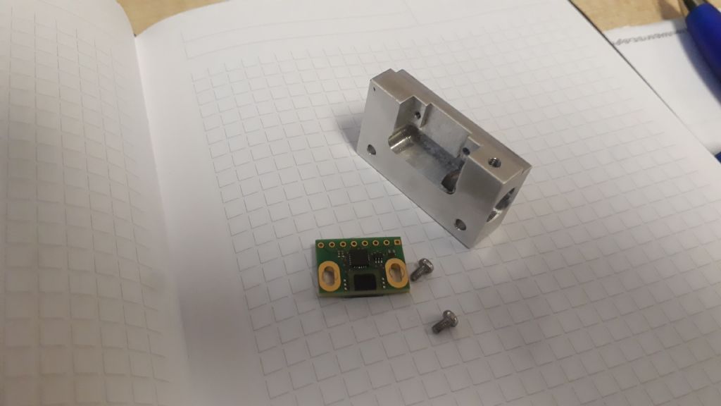
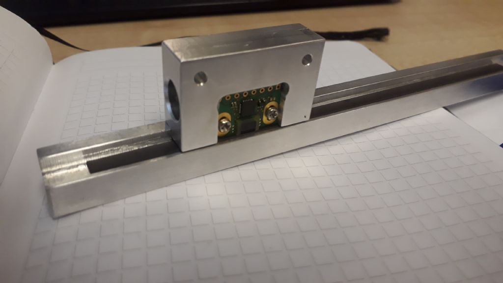
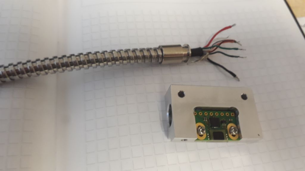
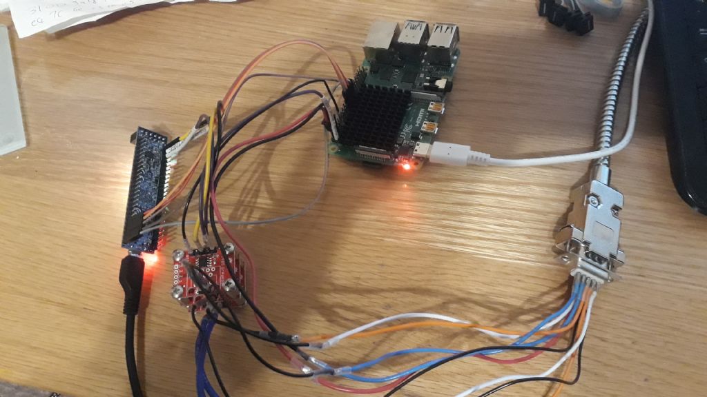
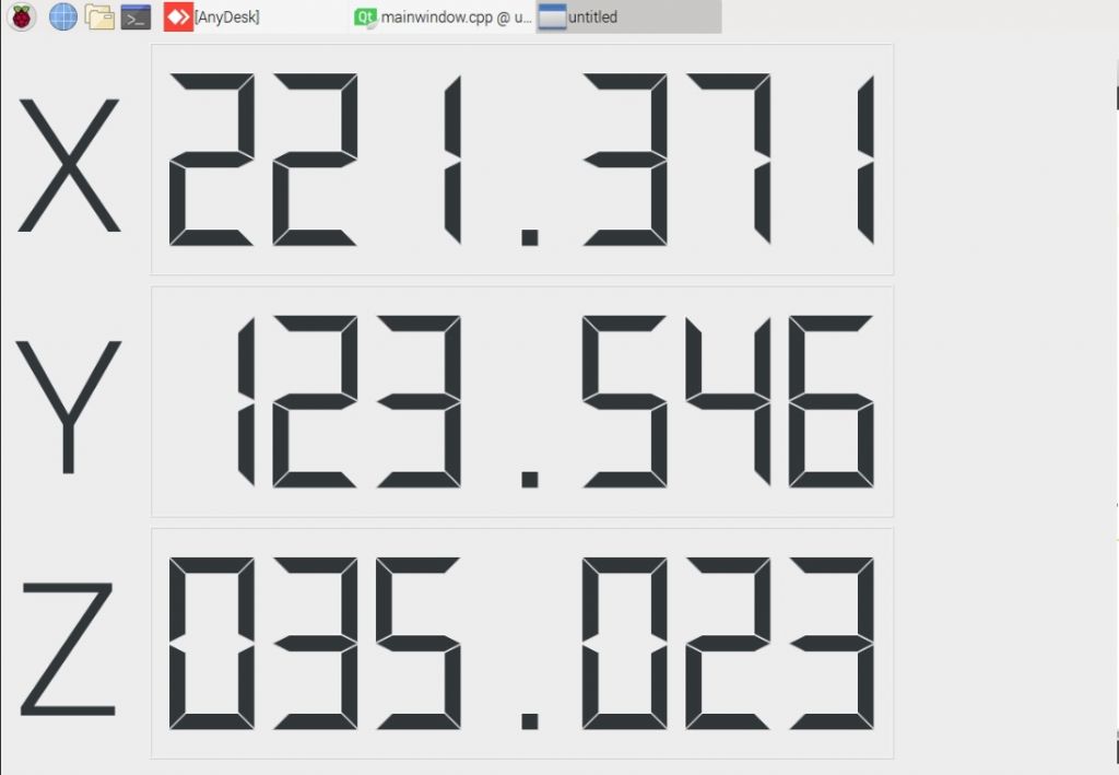
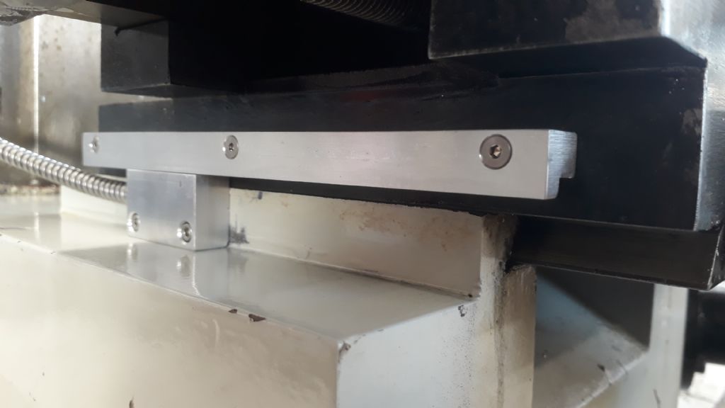
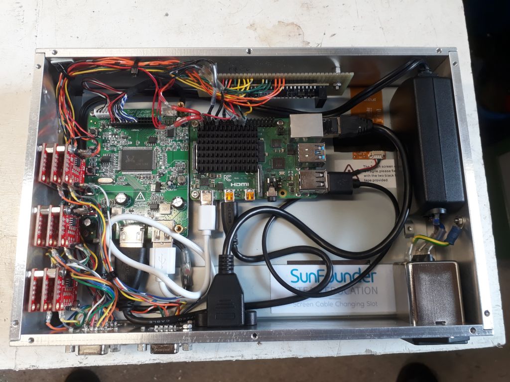
I've taken the plunge and ordered two read heads and tape, which I'll use for X/Y on my mill. If it's a success I'll roll it out to the mill Z axis, and maybe the lathe too.
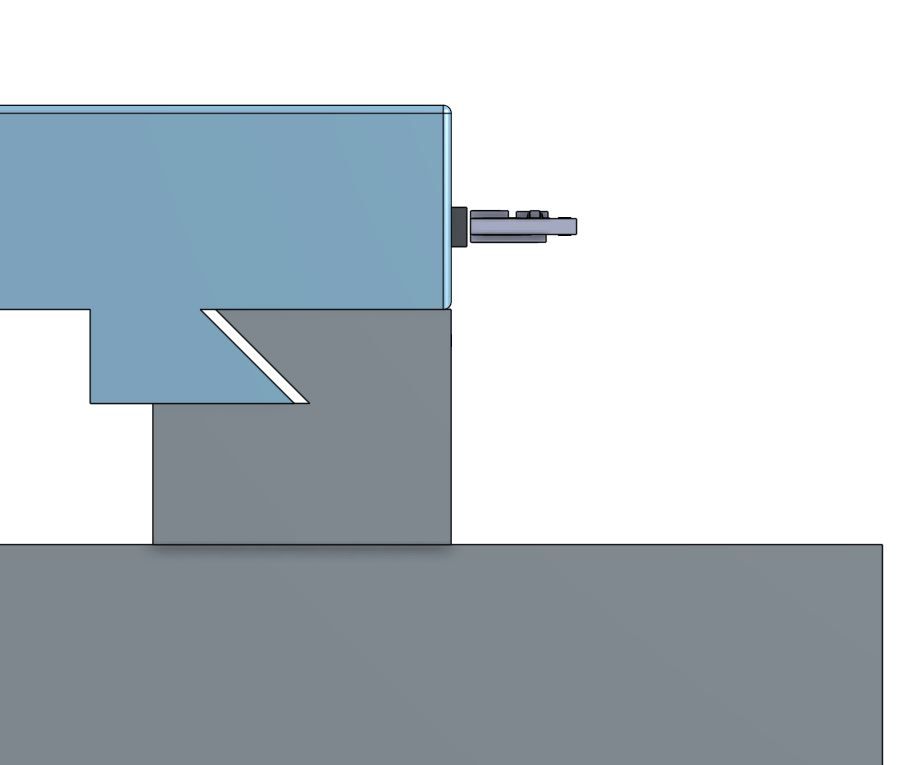
I'm still pondering the pros and cons of the various ways to mount the tape to the table, thanks for the feed-back above. I like the simplicity of mounting the tape directly to the side of the table, and see the advantages of accessibility, but it makes mounting the read-head more challenging…

I've ordered the aluminium to make the tape bracket, should I chose to go down that path, as it was cheap, but I'll probably wait until I have the read-head and tape before I decide.
For the electronics I'm planning to go full DIY. Something like…
* RS-422 receivers to convert differential signal from read head to 3.3v single-ended.
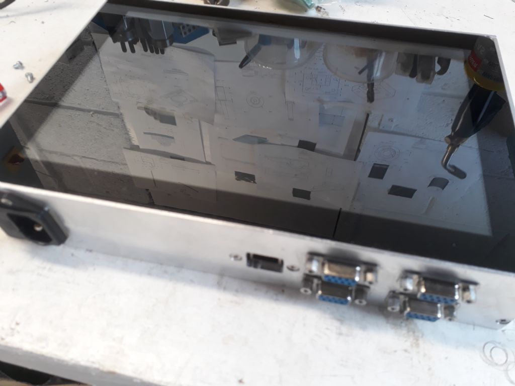
* Small programmable-logic card to count the pulses and present the data on an SPI interface. This is timing-critical "real time" stuff, which I don't like leaving to software.
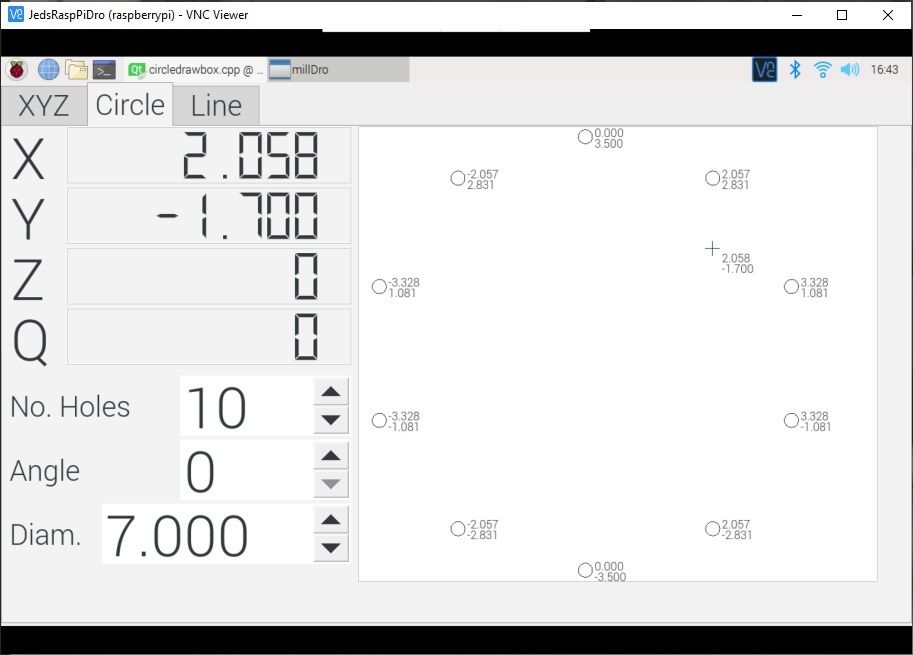
* Raspberry Pi with touch-screen, reading SPI data and running a DRO GUI. The software will be written in Qt (a cross-platform C++ IDE with decent gui/widget support)
I've used similar set-ups for other DIY projects so I'm not having to figure much out from scratch.
On a slightly different topic, I note that RLS also make rotary magnetic tapes, which are used in conjunction with the same read heads. Given that electronic lead-screws are en vogue, has anyone used a magnetic encoder instead of rotary optical encoders to track the spindle position? I imagine that the rotary tape could be fitted directly to the back of the spindle, and monitored with no physical interface, removing the timing belts and pulleys that I've seen the guys on youtube use.
ChrisB.


