D1-3 spindle nose adaptor

Advert

D1-3 spindle nose adaptor

Home Forums Work In Progress and completed items D1-3 spindle nose adaptor

Viewing 25 posts - 1 through 25 (of 53 total)
  • Author
    Posts
  • #136010
    Muzzer
    Participant
      @muzzer

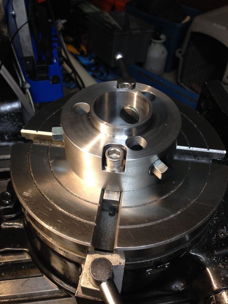
      Here's a post about an adaptor I have just completed. It replicates the D1-3 spindle nose of my lathe as a stand-alone body that can be bolted to a machine table or rotary table, allowing my lathe chucks to be used for work holding elsewhere.

      Finished!

      It's been quite an interesting exercise figuring out how to design, machine and assemble it to deliver the functionality I wanted from it. I'm not patient enough to be able to write this up as a magazine article and it's questionable if many people would want to make one anyway. However, I like reading about other people's exploits and ideas, so it seemed only reasonable to post some info on the forum in return.

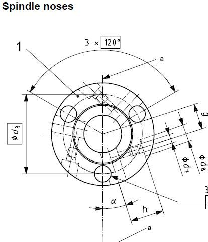
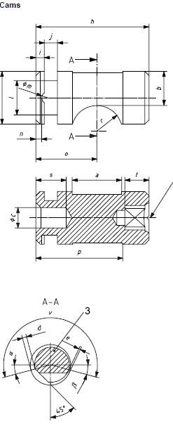
      I have a variety of chucks and fittings for my Colchester Bantam, all of which share the D1-3 Camlock system. The Camlock system uses a combination of a taper and a flat face to locate the chuck concentric and perpendicular to the lathe axis. The D1-3 size also uses 3 eccentric cams to pull the chuck against said face and taper. They act against 3 pins that stick out of the back of the chuck. As I now have 3-jaw, 4-jaw and collet chucks as well as a large faceplate and driver plate, it seemed to me that for some applications it would be very handy to be able to mount any of these either directly onto the milling machine table or onto the face of the rotary table.

      Spindle nose spec

      Cam spec

      Advert
      #31035
      Muzzer
      Participant
        @muzzer
        #136011
        Muzzer
        Participant
          @muzzer

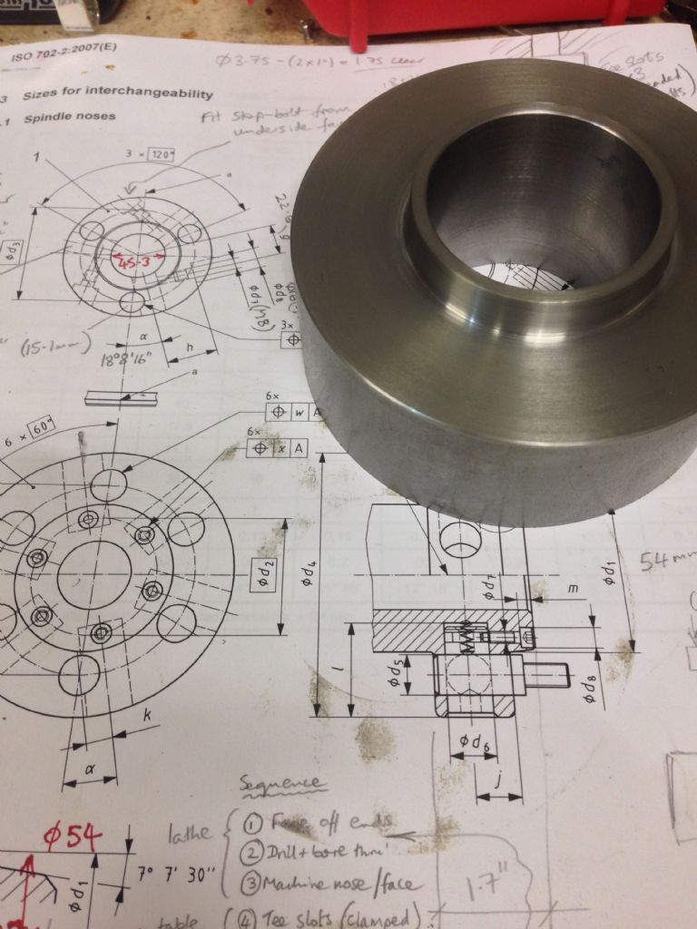
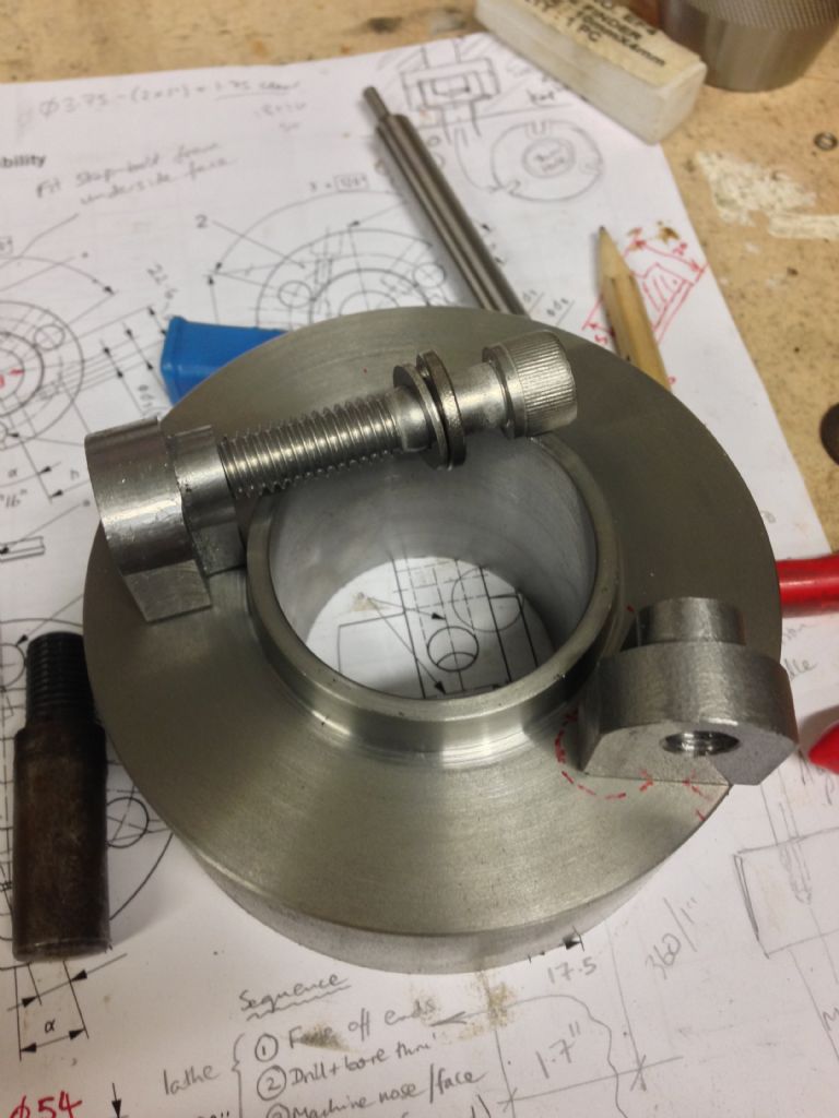
          The Camlock series dimensions are defined in the international standard ISO 702-2. I was able to locate a copy using the combined power and might of the internet and the MEW forum and thus work to the specification rather than having to rely on my own measurements. I started out by procuring a 2" length piece of mild steel of the nearest nominal diameter (4&quot. I set this up carefully in the 4-jaw, faced it off at both ends and then bored it out to 43mm to maximise the work holding capability. Finally, I formed the locating face and taper. At this point I had a spindle nose that fitted the chuck nicely but without any means of holding it on or driving it.

          Machined nose blank

          As I would be mounting the adaptor with bolts into the table in use, I drilled and recessed 2 holes at this stage, figuring that I'd find them useful for holding the adaptor during the machining operations. In some ways it would have been more convenient to have had 3 bolts but my rotary table has 4 slots. It was about then that I started to consider what a tricky challenge it would be to position all of the various radial and axial bores within the adaptor body along with the existing 2 bolt holes. It would require some devilish 3D calculations to place them all without clashing.

          Rotary table tee bolts

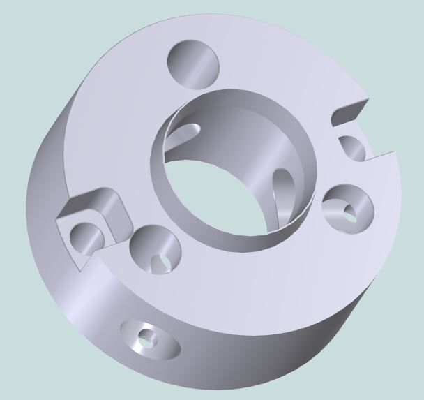
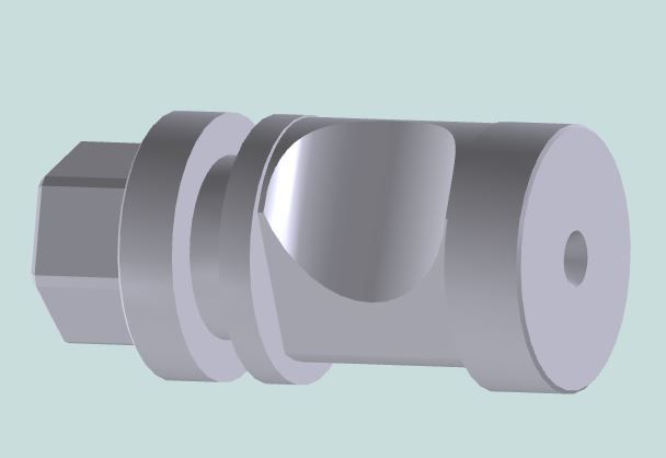
          At this point I installed a 30 day trial demo of Alibre (now called Geomagic Design, baby) and created 3D models for the existing body and the key elements of the D1-3 system, namely the 3 cams and the 3 radial (cam) and 3 axial (pin) bores. I was able to vary the angle between the 2 existing bolt holes and the rest of the components to end up with the best relative positioning by trial and error. With the hindsight now provided I could see that a larger diameter body would have been advisable but I wasn't about to copper up again for another lump of steel. I was unable to avoid one of the bolt head recesses breaking through into one of the cam bores but I figured I'd be able to modify one of the cams and thus make the whole thing workable. I also placed the cam retainer pins on the rear face of the adaptor for simplicity (you can't do this on a lathe nose). I didn't fancy trying to machine the square chuck key holes in the cams, so changed them to external hex heads that I could mill on the rotary table and tighten with a spanner or socket. I also altered the length of the cams to suit the diameter and bore of the existing body. With these 3D CAD systems you can actually spin the cams in their bores and see how the eccentrics move. Groovy.

          3D CAD model of body

          3D CAD model of modified cam

          #136012
          Muzzer
          Participant
            @muzzer

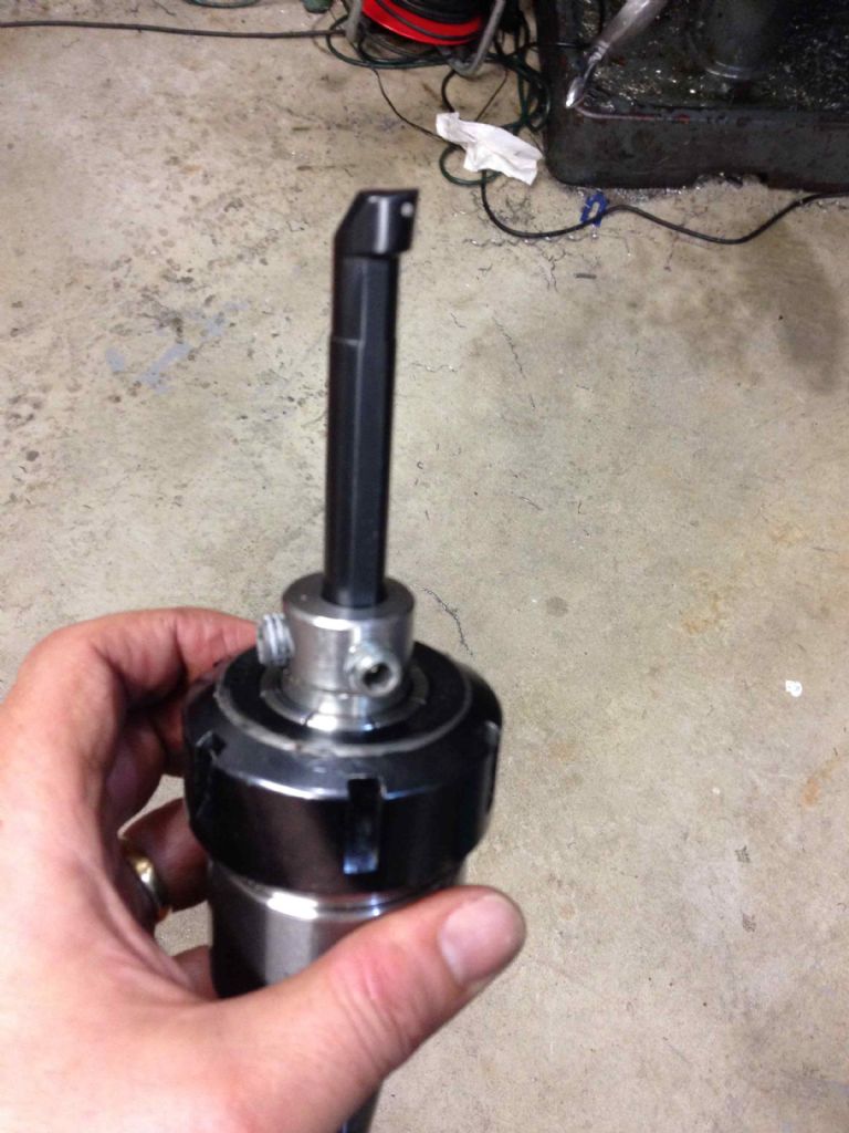
            During the machining, I managed to place the 6 bores without the degree of human error and sloppy tolerance that normally betrays my farming genes. The 3-axis DRO, centre finder and rotary table made this task considerably more straightforward than by manual means. I bored the 15mm holes for the pins and the 19mm holes for the cams using the eccentric boring bar holder I described in a post some weeks ago (“simple boring head&rdquo. The accuracy and finish were again of unsurpassed excellence by my standards. I was in uncharted waters here!

            Simple boring head

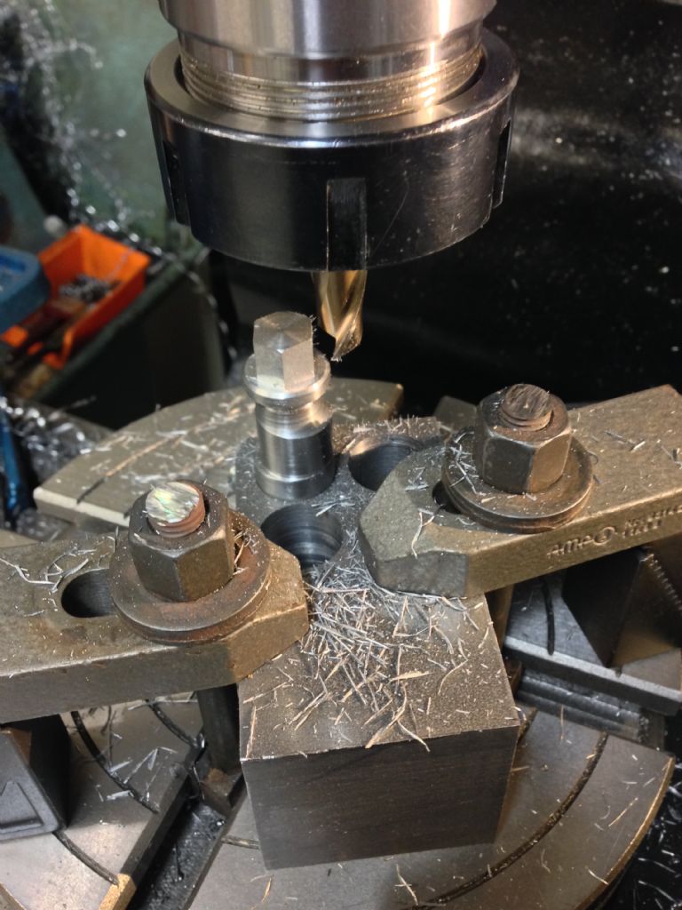
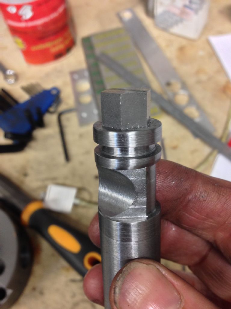
            The final challenge was the machining of the 3 cams to my own design. I obtained some "Medium Tensile Carbon Steel Bar 1045" (I am living in Canada) which looks reasonably similar to silver steel and got machining. Firstly the eccentric feature, then the retaining slot and the head. Then onto the rotary table (a collet chuck would have been handy here….) for the hex faces, the cylindrical cutout (using the boring bar again) and the machined flat. And finally a tidy up in the lathe and some deburring. Only one slight cockup here on one of them but nothing critical.

            Std and modified cams

            Machining the flats

            Finished cam blank

            #136013
            Muzzer
            Participant
              @muzzer

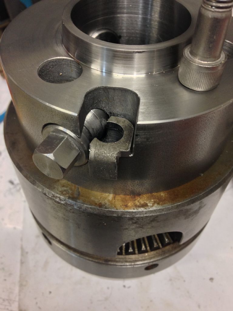
              The blessed thing actually went together like the CAD model and it works like the Real Thing fitted to the lathe. I hardened and tempered the cams using a blow lamp and a bucket of water.

              Cam retainers

              The troublesome cam - fixed

              Checking the runout

              One of the first jobs for the adaptor may be to machine some extra slots in the faceplate. It only has 4 radial slots and I fancy a couple of extra slots to give more options for holding work. I'll mount it on the rotary table and then cut said slots with the aid of the DRO for accurate positioning.

              There are several things I’d conclude from this exercise. I certainly wouldn’t have been able to calculate and optimise the correct positioning of the various bores manually. I couldn’t have positioned them correctly at the machining stage without the rotary table and the 3-axis DRO. The 3D CAD (the basic version of Albre) was relatively straightforward to get up to speed with, despite some undocumented features and indifferent technical support. And finally, I would have saved myself a fair bit of time and effort if I’d coughed up for a slightly larger blank to begin with. Overall a fairly satisfying result and one that pleasantly surprised me in terms of accuracy and relative lack of human error.

              Hope that was interesting!

              Muzzer

              #136016
              Michael Gilligan
              Participant
                @michaelgilligan61133

                Muzzer,

                Yes … that most certainly was interesting.

                A nice piece of design work, and a superb result.

                Quite honestly; this is exactly the sort of thing that I would wish to see as an article in MEW.  The work is original, and useful; and the write-up is excellent as it stands.

                … it leaves me knowing much more, and wanting to investigate further.

                Thanks !!

                MichaelG.


                Edited By Michael Gilligan on 20/11/2013 07:51:30

                #136017
                Andrew Evans
                Participant
                  @andrewevans67134

                  Muzzer

                  Interesting posts, I am thinking about making one of these at some point. Main issue I can see for me is that my mill doesn't have as much vertical clearance as yours so I need to check if the adaptor, plus chuck, plus workpiece would leave enough room for the tool.

                  #136018
                  Michael Gilligan
                  Participant
                    @michaelgilligan61133

                    P.S.

                    It's a shame about the "accidental smileys" that have crept in to your post, Muzzer … but we have learned to live with that "feature" of the forum software.

                    MichaelG.

                    #136023
                    Andrew Johnston
                    Participant
                      @andrewjohnston13878

                      Looks pretty damn fine to me, all nicely chamfered too. A real professional job.

                      Regards,

                      Andrew

                      #136026
                      David Colwill
                      Participant
                        @davidcolwill19261

                        I too have wanted such a thing but doubt I will ever end up with such a well executed end result.

                        Dave.

                        #136028
                        Chris Gunn
                        Participant
                          @chrisgunn36534

                          Muzzer thanks for that, I have advertised for a scrap spindle from a Bantam without success, so I could make something similar from it to transfer chucks from my Bantam to my rotary table and so on. It seems to me you have already done 3/4 of the work required to write it up, so I would encourage you to go a little further so we others can make one. Thanks again, Chris Gunn

                          #136038
                          Ady1
                          Participant
                            @ady1

                            Great read, and well done

                            Going to give the download. 196MB exe a try

                            Edited By Ady1 on 20/11/2013 11:40:42

                            #136058
                            John Stevenson 1
                            Participant
                              @johnstevenson1

                              I have a spare D1-3 spindle out of a CVA toolroom lathe, same as the Monarch 10EE

                              #136060
                              Thor 🇳🇴
                              Participant
                                @thor

                                Muzzer, interesting post, looks very nice. I too need something like this, unfortunately my chucks or lathes don't use the Camlock system so mine would have to be different.

                                Thor

                                #136063
                                Gray62
                                Participant
                                  @gray62
                                  Posted by John Stevenson on 20/11/2013 17:08:56:

                                  I have a spare D1-3 spindle out of a CVA toolroom lathe, same as the Monarch 10EE

                                  Don't suppose you've got a spare d1-4 spindle anywhere in the man cave have you?

                                  #136064
                                  John Stevenson 1
                                  Participant
                                    @johnstevenson1

                                    No sorry, never owned anything with a D1-4 on it.

                                    #136069
                                    SteveI
                                    Participant
                                      @stevei

                                      Hi,

                                      Muzzer – many thanks for posting this. I would love an article like this for MEW.

                                      As a beginner I have read about folks with myford spindle chucks using them on their lathes, dividing heads, rotary tables, from the lathe to the mill and back. As someone who is new to the hobby I had no choice but to opt for a cheaper lathe than a good condition myford as the prices are eye watering. It has D1-3 and I will be making a version of this. I expect plenty people have D1-4 as well. Slightly off topic but I would like to see more articles that are about making best use of these new chinese or ex industrial type machine tools and this is inline with that.

                                      Thanks,

                                      Steve

                                      #136070
                                      Sub Mandrel
                                      Participant
                                        @submandrel

                                        I'm not patient enough to be able to write this up as a magazine article and it's questionable if many people would want to make one anyway

                                        I have to disagree totally with you on both counts, Muzzer! That account would make an excellent article.

                                        Neil

                                        #136076
                                        Emgee
                                        Participant
                                          @emgee

                                          Nice work and useful bit of kit. For more fixings to the table I can recommend drilling/tapping holes in place of cutting more tee slots, just add them as required, it is all too easy to overtighten in a tee slot and hey presto a broken table.

                                          Emgee

                                          #140367
                                          Tony Ray
                                          Participant
                                            @tonyray65007

                                            Muster,

                                            Only just found this great piece of work ! I too would encourage you to write it up for the mag. If not any chance of sharing the CAD files ? A friend & I both need to make one & I have not found one commercially even if I could afford it.

                                            Regards

                                            Tony

                                            #140406
                                            Andrew Johnston
                                            Participant
                                              @andrewjohnston13878

                                              My version of Alibre has always run fine under XP.

                                              Regards,

                                              Andrew

                                              #140421
                                              Muzzer
                                              Participant
                                                @muzzer

                                                I created these parts in Alibre (now called Geomagic) using the 30 day trial. I also saved them as .PAR and .ASM files which work with Solidworks and Solid Edge – and 3D PDF files (for the models) and PDF (for the drawings). However, you lose the history (feature) tree when you export to another application like this, so if you wanted to edit them yourself it would be preferable to use Alibre. So if you have any of these CAD applications or just want the PDF and dimensioned drawings, that's no problem – let me know. Apart from the mounting bolt holes (to suit your setup), you could make most of it from the drawings.

                                                If you are planning on using one of these with a rotary table, it would be convenient if yours had 3 slots to start with. The D1-3 and D1-4 noses have 3 studs and my challenge was getting the 3 studs to co-exist with the 2 mounting slots within the adaptor. As I said, my task would have been easier if I'd started with a larger diameter lump of steel but I was brassic at the time, having just coughed up for a…..rotary table.

                                                A lot of the work is done on the rotary table, so if you have one of these already, creating the fixing holes early on helps the workflow. I also found the DRO I fitted to my milling machine to be invaluable and I suspect I'd have made a pig's ear of it otherwise. I used a centre finder a lot on this job during setup with the DRO and I'm ashamed to admit I hadn't realised how they are supposed to be used until this point! The power of Youtube!

                                                Apart from the various boring operations, careful setup of the 3 cams in the 4-jaw was the other critical activity but it all worked out nicely in the end. I've now used it a few times since I made it and it's been pretty useful.

                                                I'm really not likely to write up anything for the magazine. I'm much more inclined to use my free time in the workshop but you'll notice I've created a couple of short photo journal type postings like this which I hope people find interesting in the same way I do when I browse other people's work looking for ideas and inspiration.

                                                Muzzer

                                                #140565
                                                Tony Ray
                                                Participant
                                                  @tonyray65007

                                                  Muzzer,

                                                  I understand re workshop time but please do keep the photo journal stuff coming !

                                                  If you would share the Alibre and PDF files If I can't get Geomagic going I'll have the PDFs as a backup. Like you I have a 4 slot rotary. Apart form objections of raising the overall fixture height I wondered if you considered an adaptor plate ? Plate of a larger dia than fixture – with 4 holes to suit rotary table and 3 inner mounting holes offset by 60 degrees to the camlock stud postion. Perhaps it did not fit with your cash position at the time.

                                                  Yes Youtube is great – I learned that I could draw (sketch).

                                                  I'll PM you re files

                                                  Thanks again

                                                  Tony

                                                  #140619
                                                  Muzzer
                                                  Participant
                                                    @muzzer

                                                    The main issue with adaptor plates is that I have a selection of chucks and faceplates and don't want to disassemble them each time just to use them – and I don't want to go out and buy a load more chucks with a different mount. My adaptor height is set by the length of the Camlock pins. The collet chuck exaggerates the height stackup but there again I have a full-sized machine so it isn't usually going to be a problem. What milling machine do you have?

                                                    I'll send you the files when I get home. When you are ready, you can install Geomagic and have a go with the trial. The basic version is pretty cheap to buy if you find you like it. It wasn't too bad really.

                                                    Muzzer

                                                    #140685
                                                    Tony Ray
                                                    Participant
                                                      @tonyray65007

                                                      Muzzer,

                                                      i have an SX3 mill,380mm is the max spindle to table distance on the R8 variant and my friend has an Adcock & Shipley universal. He has a Bantam & I have an M250 both are d1-3 which is handy.

                                                      That's a nice collet chuck is it a multibore ?

                                                      Thanks for the files too

                                                      Tony

                                                    Viewing 25 posts - 1 through 25 (of 53 total)
                                                    • Please log in to reply to this topic. Registering is free and easy using the links on the menu at the top of this page.

                                                    Advert

                                                    Latest Replies

                                                    Viewing 25 topics - 1 through 25 (of 25 total)
                                                    Viewing 25 topics - 1 through 25 (of 25 total)

                                                    View full reply list.

                                                    Advert