cnc lathe spindle speed control problem

Advert

cnc lathe spindle speed control problem

Home Forums General Questions cnc lathe spindle speed control problem

Viewing 22 posts - 1 through 22 (of 22 total)
  • Author
    Posts
  • #223021
    Trev67
    Participant
      @trev67

      Hi

      I have a Denford Starturn 8 cnc lathe that I'm trying to get working on linux cnc. I have the axes moving and spindle switching on and off, I would like to get the spindle speed under computer control as well.

      The speed controller is a JAY JE124/1. It controls a 160v dc motor. It currently has a manual pot to control it. I know about the issues of the control side not being earthed and having a floating voltage.

      I've seen lots of references to these controls having a 10k pot and 0 -10v to control the speed. Taking some measurements it seems like my pot is 3.5k and the voltage across it is 3.7v. If I check the voltage from the pot terminals to ground, I get strange readings, so I assume this is floating, and needs to be kept isolated.

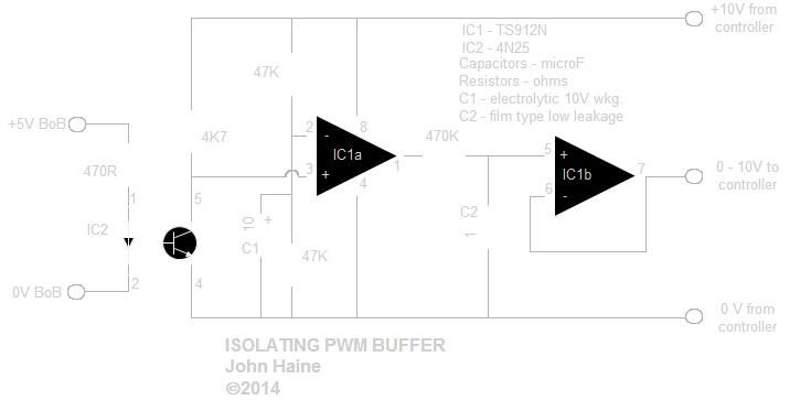
      I've found a circuit diagram which I will try to add to this post, it's by John Haine, who seems to be on here, so John if you read this, you may be the man to help.

      With reference to this circuit, it appears to be isolated, so that is good, also the voltage it is controling seems to be derived from the speed controller, so if it is being supplied 3.7v instead of 10v will I get a 0 – 3.7v control, or will this not be enought to make the circuit work.

      My knowledge of electronics is very limited, all I know is if you let the smoke out it doesn't work, so if somebody could advise on this circuit I would be very grateful.

      Thanks in advance for any help, and thanks John for producing the circuit diagram in the first place.

      Trevor

      Advert
      #24349
      Trev67
      Participant
        @trev67
        #223022
        Trev67
        Participant
          @trev67

          Hi

          Could get the circuit diagram onto the posting I think I managed to save it in my album as a jpeg, hope its possible to see it.

          Thanks again

          Trevor

          #223023
          Emgee
          Participant
            @emgee

            Trevor

            Have a look at the Homann site for a solution, he does a board to provide the same function as the manual pot but controlled from Mach, link as follows.

            http://homanndesigns.com/index.php?main_page=index&cPath=1&zenid=sm3s1t10peg5d5cj57itvukvh3

            Emgee

            Edited By Emgee on 29/01/2016 11:31:41

            #223041
            Another JohnS
            Participant
              @anotherjohns

              Hi Trevor;

              I have two mills controlled by LinuxCNC, with spindle control.

              General notes:

              1) The CNC controllers SHOULD have opto-isolated spindle control. (check for the wording). Opto-isolated means that the CNC lathe/mill supplies power and ground to the CNC controller, and the CNC controller only moves the output voltage between what it is given.

              2) 0-10v is an absolute. IIRC, my KX1 is 0-5v, and it works very well.

              3) On the KX1 mill, the spindle controller had a little transformer, and following the wires/traces, it was obvious that it was separate (ground, +5v, input) than for the remainder of the mill. This is about as dangerous to you as say, handling a 9v battery.

              4) on the other mill (with a generic KB-120 style DC motor controller board) the potentiometer "floated" about 100v. (in North America, 120v supply, UK might be different). Additionally, after testing, the motor controller would not provide enough "oomph" to drive the opto-isolators. So, I added an external power supply tied to the positive and ground pins of the CNC controller, with the output and ground pins of the CNC controller going to the motor controller. This circuitry came from the KBIC manual, found on line.

              5) You are correct to be cautious, so good for you. But, it is not rocket science.

              6) I did put quite a bit of info up at a blog, including slides I presented from last years' CNC Workshop in the USA here: **LINK**

              Look around that site, I think I put quite a bit up on it about spindle control (I have not updated it in a while, but the info should still be relevant.

              John.

              #223043
              Muzzer
              Participant
                @muzzer

                Can you post the link to the circuit diagram?

                If it's floating this is normally so it can be connected to a low voltage, user-accessible interface rather than having mains voltage present on a pendant etc.

                On the face of it, if you have 3.5Vdc across the pot, you should be able to drive it with a 0-3.5Vdc signal.

                We should be able to get a better idea from the cct dia. You could also check the resistance from this part of the circuit to ground. I would expect it to read very high resistance (>>1M Ohm). If so, you should be able to ground the 0V of this circuit or the LinuxCNC controller BOB rather than have it floating.

                Murray

                #223055
                Trev67
                Participant
                  @trev67

                  Hi,

                  Thank you to everybody who has replied, I'll have a look at the links.

                  Here is the circuit I was refering to in the original post. I was hoping this might be suitable for a number of reasons:

                  1. The input is a PWM signal, this is easy to set up in linux, I do have a spindle control board, but it uses the A axis step signal, and this is trickier to set up in linux (easy in mach 3 I think).

                  2. The 10v and 0v are derived from the motor controller, so if these are 3.7v and 0v will it still work and give me a proportional voltage to control the speed.

                  3. This circuit appears to be isolated, so if I have got a floating voltage on the control side of the motor controller, then it should be ok.

                  4. If the 3.7v isn't enough to drive this control circuit , is it possible to alter the values of some resistors to make it work, or even supply it with an external voltage to power the circuit, without affecting the 3.7v on the output. ( I have 5v and 12v available from the breakout board)

                  5. The commercial boards all seem to work at 0 – 10v, I'm concerned that it will either run at full speed most of the time, or possibly damage the motor controller.

                  I hope the picture is visible, It was a .png file, I had to invert the colours, and save as a jpeg, so it is a bit feint.

                  Many thanks

                  Trevor.
                  vfd control circuit.jpg

                  #223064
                  Muzzer
                  Participant
                    @muzzer

                    It's a pretty crude circuit. The opamp claims rail-to-rail inputs and outputs down to 2.7V, so on the face of it should work down to 3.5V but the opto is always a bit of an unknown when you try to use it in linear mode like this. It'll be very non-linear, as the LED won't start to conduct until about 1.5V and then everything will start to happen. Might be OK if you have a closed loop (speed sensor) which I suspect you don't, otherwise may be rather disappointing.

                    More grown-up isolators will transfer the voltage across the isolation barrier without such distortion. Some of the Mesa interface boards like the 7i76 I'm using have an isolated analogue channel for this very purpose but changing over to one of those may be a bit extreme.

                    Perhaps somebody can suggest a better alternative apart from the Mesa boards? Sorry, I don't know any myself. The digispeed looks like a possibility but can't easily tell how good it is.

                    Murray

                    Edited By Muzzer on 29/01/2016 18:08:30

                    #223103
                    Anonymous

                      Errrr, I assume the input is a PWM signal not analogue? So basically the opto isolates the signal, the first opamp acts as a 'comparator' to square up the slooooow opto followed by an RC filter and the second opamp as a buffer.

                      It's not quite how I'd design the circuit, but what do I know.

                      One way of transfering a precision analogue signal across an isolation barrier is to use a V-to-F, opto and then a F-to-V on the other side.

                      Andrew

                      #223105
                      Muzzer
                      Participant
                        @muzzer

                        Haha, yes the clue's in the name! Didn't spot the PWM in the title, relying more on Trevor's description of analogue voltages. Senior moments…

                        Edited By Muzzer on 29/01/2016 20:21:28

                        #223128
                        John Haine
                        Participant
                          @johnhaine32865

                          Yes, I admit it, its mine! I drew it up on another forum as someone was just about to make a lot of smoke by connecting their KBIC controller control voltage input to a ground referenced BoB. The method of working is exactly as Muzzer and Andrew surmise, the opto transfers PWM, there's a comparator to square it up, a simple low pass filter, and a buffer. I didn't build it but the person I was helping did and apparently it works perfectly once built right. He even designed a pcb and kindly gave me a couple, and when I get a tuit I'm going to add it to my Denford.

                          Again as Muzzer says the op amp is selected as it will will swing very nearly rail to rail, and should work at 3.7 volts. However you'll have to look out for the 3.5v that drives the pot having enough current to drive the circuit in particular the opto transistor that will take 2/3 mA in its on state. Are you sure it's 3.5 v and not 10? 0 – 10 v is pretty standard for industrial controls like this. Hope this helps, just ask any questions.

                          #223134
                          Trev67
                          Participant
                            @trev67

                            I'm pretty sure the voltage is no 0 -10v

                            I am measuring the voltage with the motor running, across the outer two terminals of the pot there is 3.7v, if I measure the low side and the centre I get between 0 – 3.7v as I move the control. This seemed strange to me as I was expecting 0 – 10v. The only other reference to this control board I could find on the web was someone on another forum who had one on a Starmill. The thread died out just after the poster was being told about 0 -10v, maybe he dissappeared in a puff of smoke!

                            I do have a SpindleV5 board from diycnc, but I have two issues, the output is just two terminals 0v and 0-10v, so I'm guessing that it would make my motor run at full speed from 1/3 upwards, and the extra voltage could damage the motor controller. The other problem is that it uses the A axis step signal to control the speed instead of PWM. This is more difficult for a novice like me to configure in linux, so I'm thinking that it is not really suitable.

                            If the original circuit that I posted is not suitable, I found others in this post on the mach forum**LINK**

                            Could one of these work but with a 5v power supply?

                            Thanks for you help

                            #223173
                            Muzzer
                            Participant
                              @muzzer

                              The circuit in the link works in pretty much the same way as John's but has the complication of an additional IC. John has avoided the need for it by using a double opamp.

                              As John says, you may find that when you try to power either of these circuits from the top of the pot (3.5V) there isn't enough current available. I suspect there's a fair chance that you are seeing 3.5V because there is actually a series resistor in series with the top of the pot. If I'm right, it will collapse when you connect your circuit.

                              If instead you powered your circuit with an external supply (eg a simple 10V wall wart) and it generated a 0-10V output, you could simply reduce it with a couple of resistors to give 0-3.5V output. You could then feed this into the wire that came from the pot and everything should work. Alternatively, John's circuit should work with a 3.5V external supply if you can find one. That might be simpler. If you use a 5V supply, perhaps you can set up the output in LinuxCNC to only generate 0-70% PWM, which ought to have the desired effect?

                              Sounds as if the SpindleV5 board converts frequency to voltage, not PWM to voltage, otherwise it might have worked here. Would still have needed an external supply though.

                              Murray

                              Edited By Muzzer on 30/01/2016 10:58:45

                              #223210
                              John Haine
                              Participant
                                @johnhaine32865

                                As Murray says, it's easy to adjust the output max voltage, though I would do so by adding a resistor in parallel with C2, which would mean that the output impedance driving the control voltage input will be from the voltage follower IC1b. As for powering the circuit, I suggest the best approach is to buy a switched mode "wall wart" giving 12 volts, as these give a "floating" output as they are not ground referenced at all. £9.99 buys you one from Maplin, stock code N93JU.  By the way, the reason for IC1a is only partly to square up the slow output from the opto, it's mainly to ensure that the smoothed voltage at C2 can swing rail to rail.

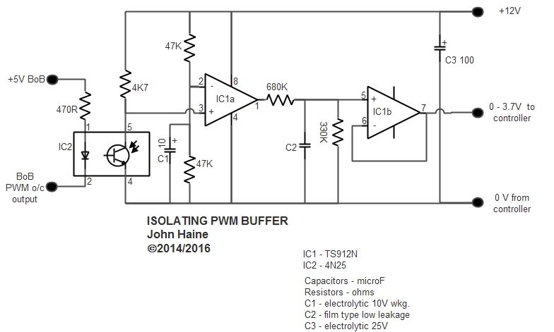
                                iso_buffer.jpg

                                Right, so here is a modified version of the circuit, with the resistors that smooth the PWM adjusted in value to give a maximum output voltage of ~3.7 volts.  The other change is that I suggest you add C3 as a smoothing cap if using a wall wart; also I've corrected the labelling of the input, pin 2 of the opto-coupler IC2 goes to the PWM output on your BoB, which should be open-collector (they usually are IIRC); and you need to set Linux CNC so that the PWM output is active low.  The other important config parameter is what in March 3 is called "PWM Base Frequency", which is recommended to be in the region of 25 Hz.  The changes here could be accomodated on the existing PCB design.

                                Edited By John Haine on 30/01/2016 14:05:53

                                #223220
                                Neil Wyatt
                                Moderator
                                  @neilwyatt

                                  Why not just use a single comparator?

                                  Neil

                                  #223226
                                  Trev67
                                  Participant
                                    @trev67

                                    Many thanks John, thats what I was hoping for. I guessed the original circuit was on the right lines, but would need tweaking to work with the different voltage. Now to get it built and see if it works!

                                    Thanks to everybody who has contributed to this thread, my electronics knowledge is not very good, some of the discussion is over my head. However I've tried to follow it and learn a bit more.

                                    If anybody would like to explain in simply terms how this circuit works and how the design is arrived at I'd like to know. I know what PWM is and resistors and capacitors, opamps are a new on me so it's a bit of a learning experience.

                                    Neil, why not a single comparator? I havn't got a clue, it's all way over my head, perhaps you'd like to explain the circuit and come up with something simpler that would do the job?

                                    Thanks again

                                    Trevor

                                    #223229
                                    Anonymous
                                      Posted by Neil Wyatt on 30/01/2016 15:01:27:

                                      Why not just use a single comparator?

                                      Errr, because you're trying to produce an analogue voltage from a digital signal, so you need a low pass filter to remove all frequency components other than DC. Opamps don't make good comparators, but comparators make even worse opamps. crook

                                      Andrew

                                      #223236
                                      Emgee
                                      Participant
                                        @emgee

                                        John

                                        What value do you suggest for C1 and C2 please ?

                                        Emgee

                                        #223237
                                        John Haine
                                        Participant
                                          @johnhaine32865

                                          The circuit works as follows. At the input, the PWM signal at the BoB is turning on and off the output transistor. When it's ON current flows through the 470R resistor and the LED hidden inside the opto emits light. That turns on the associated transistor as the light hits its base – you can't see this happening as it's hidden inside the IC2 package. The LED and transistor are electrically isolated, the only "connection" being by the light signal – this gives us the electrical isolation we want.

                                          When the opto transistor turns on, its collector at IC2 pin 5 pulls down to 0 volts; when it's off it rises to 12 volts. So the waveform is the "negative" of the PWM signal. The comparator IC1a inverts this and has a 0 – 12 volt square wave at its output which is in phase with the PWM signal. As I said in my last post IC1 is a type which can truly swing from rail to rail, most op-amps can only get to within half a volt or so of either or both. This gets smoothed by the combination of the two resistors and capacitor C2 – so the smoothed voltage goes from 0v when the mark/space ratio of the PWM is zero to 12v when it's 100%. This is what we want, but s the input impedance of the controller is a bit of an unknown quantity, it might load the capacitor and affect the voltage, IC1b is wired as a "voltage follower" buffer which just outputs the same voltage on pin 7 as goes in on pin 5, but at low impedance. Given you get two opamps in a package and no external components are needed around IC1b, it's a no-brainer.

                                          I designed this circuit originally to interface to a motor driver that needed 0-10 volts for control and provides a 10V 10 mA output which can be used by external circuits – this seems to be quite common on drives, it's on both the KBIC DC otor control in my Novamill and also the VFD I have on my big mill. An isolating buffer needs a power supply that's isolated from ground, and if you use this "built-in" supply it inconveniently doesn't give you any head-room between the supply voltage and the maximum control volts needed. Hence the choice of op-amp.

                                          Trev, an op-amp is a very common analogue building block. Basically it has two inputs, + and -, and an output voltage which is the difference between the two inputs times a VERY large gain – typically 10,000 or more. As shown here, it's used in two ways. In the first the + input is held at half the supply voltage, i.e 6v, while the – input has the inverted PWM signal from the opto. Basically the output ill be the opposite of the input – so 0v or 12v – except over a very small input range around 6v as the input swings. In the second, the voltage on C2 goes on the + input, and the output is fed back to the – input; the very high gain of the amp makes sure that the output voltage has to equal the input. The TS912 has some nice properties, its outputs can swing virtually over the full range of supply voltage (most opamps being limited at one end or the other) and it has a very very high input impedance.

                                          EmGee, as it says on the circuit, C1 10 microfarad say 10V working electrolytic; C2 1 mfd film type (for low leakage – not electrolytic); C3 100 mfd 25V.  None of them are critical.

                                          Edited By John Haine on 30/01/2016 17:03:52

                                          #223412
                                          Trev67
                                          Participant
                                            @trev67

                                            John

                                            Thanks for explaining it, I do kind of understand, but not to the extent that I could come up with the design myself.

                                            It was only when I look at the data sheet I realised that the two op amps are actually in one component, so I see what you mean about it being a no brainer to use both.

                                            When I get this up and running I'll report back. I did find it very frustrating when trawling the web for answers that many forum threads, just die out without reaching a conclusion.

                                            Thanks everybody , especially John

                                            Regards

                                            Trevor

                                            #223424
                                            Danny M2Z
                                            Participant
                                              @dannym2z

                                              In the above cct diagram, IC1a appears to have the – and + signs (inverting & non-inverting) inputs transposed.

                                              Not being picky, but it is important for somebody trying to follow the cct operation. John's description does actually correct this though.

                                              It's quite a nifty little interface, thanks for publishing it.

                                              * Danny M *

                                              #223436
                                              John Haine
                                              Participant
                                                @johnhaine32865

                                                Oops! Actually I'd forgotten how I designed it. IC1a works as just a comparator not an inverter. The circuit diagram and pin labelling is correct, my description isn't. Since Mach3 allows you to select the sense of the PWM it doesn't matter, I hope Linux cnc allows the same.

                                              Viewing 22 posts - 1 through 22 (of 22 total)
                                              • Please log in to reply to this topic. Registering is free and easy using the links on the menu at the top of this page.

                                              Advert

                                              Latest Replies

                                              Home Forums General Questions Topics

                                              Viewing 25 topics - 1 through 25 (of 25 total)
                                              Viewing 25 topics - 1 through 25 (of 25 total)

                                              View full reply list.

                                              Advert

                                              Newsletter Sign-up