Chester Conquest mini mill

Advert

Chester Conquest mini mill

Home Forums Manual machine tools Chester Conquest mini mill

  • This topic has 38 replies, 8 voices, and was last updated 9 May 2018 at 16:48 by John Murphy 3.
Viewing 25 posts - 1 through 25 (of 39 total)
  • Author
    Posts
  • #13214
    John Murphy 3
    Participant
      @johnmurphy3

      Modifications

      Advert
      #352741
      John Murphy 3
      Participant
        @johnmurphy3

        Hello everyone. Im just after buying a secondhand chester mini mill (x2).could anyone be able to answer a few questions I have with this mill? Its an x2 mill with a tilting column. Has a gas strut, 130mm x 300m travel. The motor is a 350w version with a xmt 2335 control board.

        1. Can the solid column sold by arceurotrade be a direct swap or will the dovetails need machining to fit. Or would I be better off just making up a bracket to lock the column and brace it.

        2. Is it true the 350w is hobbled by the control board so it won’t break the gears. If so are there mods that can be done to get the the full power for the motor.

        I’m planning to get a belt conversion.

        I’m mainly going to be using the mill for motorcycle stuff. So I’d like to be able to fly cut and hopefully be able to make 1mm DOC in steel.

        #352778
        Neil Wyatt
        Moderator
          @neilwyatt

          Hello John,

          I had great success with a bracket on my X2, but one day I will probably fit the upgrade.

          Give Arc a call and ask if the column will fit a Chester X2?

          Neil

          #352783
          John Murphy 3
          Participant
            @johnmurphy3

            Hi Neil , have you pics of your bracket? I rang arc yesterday, was put off by them saying it may need machining/filing/scraping , the more I think of it I think it wont need machining. The chester is 130/300 travel with 460 x 120mm table which says to me its the bigger table than the original x2. So the the Arc conversion kit will be a straight swap.

            Edited By John Murphy 3 on 04/05/2018 10:23:15

            #352787
            Russell Eberhardt
            Participant
              @russelleberhardt48058
              Posted by John Murphy 3 on 04/05/2018 10:22:27:
              was put off by them saying it may need machining/filing/scraping , the more I think of it I think it wont need machining.

              I bought an X2 mill a few years back which came with the fixed column in place. It still needed to be removed and shimmed slightly to get it trammed correctly. That may be what they are thinking.

              Russell

              #352788
              Ketan Swali
              Participant
                @ketanswali79440

                Hello John M,

                You probably spoke with our Ian yesterday. He is on holiday today, so I cant check with him. Anyway, if he talked about machining/filing/scraping, he was referring to the base of the column and/or the base on which the column sits.

                If you were put off, then you might need to consider shimming in between the base and the column. All of this depends on your engineering knowledge/ability/experience. Also, it depends on what parentage the machine from Chester is, i.e. is it from SIEG or not. If it is from SIEG, less work may need to be done. If from some other factory, then more work may need to be done. All depends on your skill. Playing with the dovetails 'might be' an issue.

                With reference to your point 2 – specifically for the X2 (not the SX2, as it has a belt drive): motor is controlled by the control board, but it would be wrong to say and presume that the gears will not break as a result of this. The nylon gears are sacrificial, designed to break in case of overload, in turn trying to protect the control board. It is not a 'full fail safe?' system, and in certain cases, under certain circumstances, there could still be damage to components on the control board, due to certain overload events, and/or user related issues.

                Your point: ' If so are there mods that can be done to get the the full power for the motor.' – straight answer : the motor and control board combination as supplied is correct. Any thought of changes or tweaking of the control board to increase speed will result in loss of torque or vise versa, and should be removed out of ones thought process. Also, there is a firm relationship between 'electrical' and 'mechanical'. Changes in the electrical can adversely effect the mechanical.

                Belt conversion: there are good, bad and ugly kits out there. If you have good engineering knowledge – well and good. If you are thinking of DIY without knowledge, results could be good or bad.

                Flycutting : one of the biggest causes of breaking gears/control boards,… mainly due to lack of knowledge of limitations, of feed, speed and depth of cuts when using fly cutters on different materials.

                Ketan at ARC.

                #352791
                Neil Wyatt
                Moderator
                  @neilwyatt

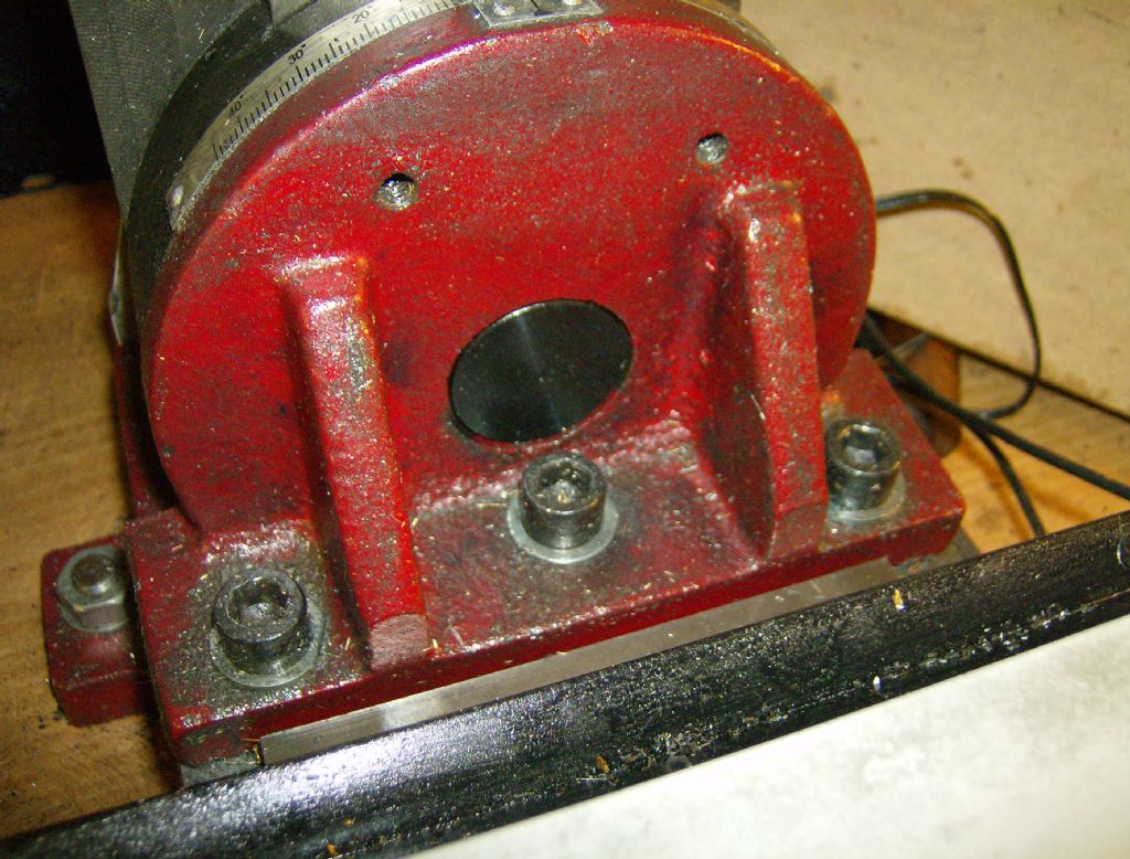
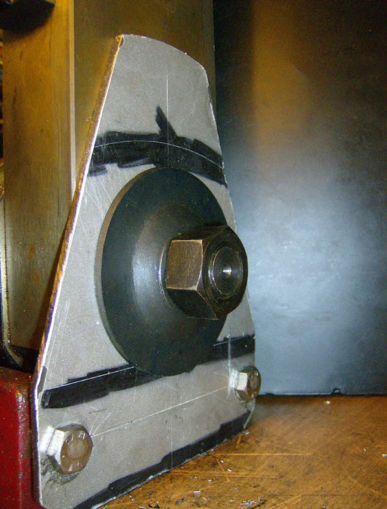
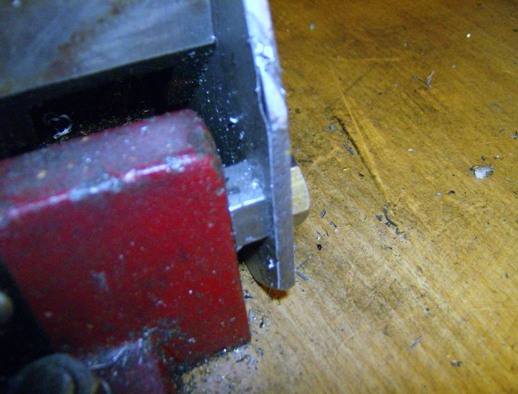
                  I scraped the bottom of the right angle bracket for the tilting column anyway, which improved rigidity and alignment. The three fixings almost in a straight line design is not the best… even if the new column is dead on the base may not be perfect. The scraping doesn't need to be pretty, just see which way it needs to go for improved accuracy and keep removing material gradually until you get as large a contact patch as possible. I used the end of a bar of HSS, you need to keep resharpening it!

                  x2_(2).jpg

                  You can see my bracket and spacer arrangement in the pics. The bracket is 5mm thick steel (with a plastic coating – originally the base of a tall loudspeaker), but plenty stiff enough. Files the spacers to be a close fit. Make sure the M10 fixing holes are aligned with the maximum meat in the base casting

                  x2_(6).jpg

                  x2_(7).jpg

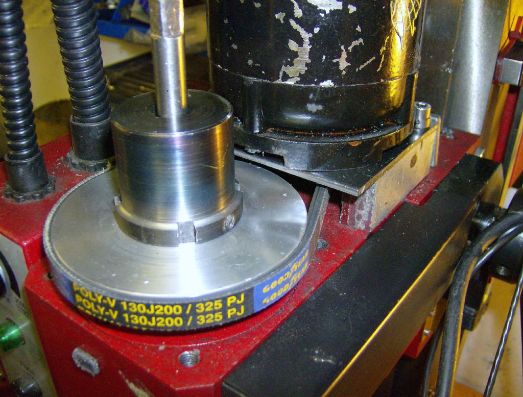
                  I also did a belt drive conversion and angular contact bearing swap at the same time.

                  This was written up in MEW in full, issue 199/201, before I became ed.

                  Neil

                  #352793
                  John Murphy 3
                  Participant
                    @johnmurphy3

                    Ketan thank you very much for the lengthy reply much appreciated, how do I tell if it came from the sieg factory? Its looks the very same as the original x2 but with more travel and bigger table. 130×300 travel with 460×120 table. Link below. I don’t mind doing work to the base of the column but dovetail work would be outside my skills.

                    http://www.tphmachinetools.co.uk/products/1501-new-chester-conquest-mill-super

                    Edited By John Murphy 3 on 04/05/2018 11:31:13

                    #352795
                    John Murphy 3
                    Participant
                      @johnmurphy3

                      Neil fantastic , thank you

                      #352796
                      Neil Wyatt
                      Moderator
                        @neilwyatt
                        Posted by Ketan Swali on 04/05/2018 11:22:43:

                        Belt conversion: there are good, bad and ugly kits out there. If you have good engineering knowledge – well and good. If you are thinking of DIY without knowledge, results could be good or bad.

                        My DIY belt conversion definitely comes into the 'ugly' category, it did reduce the top speed a bit, but IMHO it greatly improved the machine – I prefer a bit of belt slip top a broken gear

                        x2_(11).jpg

                        The original X2 as supplied has ample power for its rigidity; possibly a solid column modded machine could use more power, but if forking out for upgrading column, belt drive and motor/speed controller at the same time, why not just buy an SX3, sell the X2 to cover most of the difference and be done with it?

                        Neil

                        #352798
                        Ketan Swali
                        Participant
                          @ketanswali79440
                          Posted by John Murphy 3 on 04/05/2018 11:30:14:
                          Ketan thank you very much for the lengthy reply much appreciated, how do I tell if it came from the sieg factory? Its looks the very same as the original x2 but with more travel and bigger table. 130×300 travel with 460×120 table. Link below. I don't mind doing work to the base of the column but dovetail work would be outside my skills.

                          http://www.tphmachinetools.co.uk/products/1501-new-chester-conquest-mill-super

                          Edited By John Murphy 3 on 04/05/2018 11:31:13

                          Ummm, looking at it, there is a 90% chance it is a SIEG. Difficult to be 100% sure.

                          Is that the specific one you are intending to buy, at that price?…. if so, and if you are considering fixed column and belt drive conversions, then I believe that you should review your total costs in components and labour needed to carry out the work, and see if it is really worth it, for you. Also, only consider to do these modifications if really necessary – in your particular case, after you have got used to the machine and its limitations.

                          Ketan at ARC

                          #352802
                          Ketan Swali
                          Participant
                            @ketanswali79440

                            John M,

                            I think the Chester machine you linked to with 460×120 table is like to be SIEG X2L as in this link, rather than the original X2 base, which is different.

                            If so, then you will probably need the column which fits on the SX2LF machine Part SX2LF-53.

                            However, the mounting holes for the column on the base of your machine may or may not be the same, as the mounting holes on your machine are designed for the tilting column casting to fit on it, where as the mounting holes on the fixed column are designed to fit directly to the base of a fixed base design. If this is what you find, then you may have to make an adapter plate to deal with this. We have not come across the SIEG X2L machine, so we are unable to guide on this.

                            Ketan at ARC.

                            #352839
                            John Murphy 3
                            Participant
                              @johnmurphy3

                              No I bought this machine second hand cheap. Seems to be in good condition. I have the table saddle etc removed to check things . I’ll remove the head tomorrow and check that. Yes ketan that was another option i was thinking , I could just make up an adapter and fit just the column. I noticed all the gib strips where not machined correctly for the gib screws , so I’ll sort that before I put the table back on. I see ye sell the sx2l base as well. I have a scrap bit of c channel steel in the garage. Make up a brace and see what its like. But I’d imagine it still would not be as rigid as the solid column due to the increase of thickness but also even the braced tilting column still has that crap bolt going throw it Really bad design. What can these little mills DOC be in steel and aluminium? With let’s say a 4 flute 10mm end mill.

                              Edited By John Murphy 3 on 04/05/2018 19:39:27

                              Edited By John Murphy 3 on 04/05/2018 19:54:30

                              #352841
                              John Murphy 3
                              Participant
                                @johnmurphy3

                                Neil , doesn’t matter what it looks like once it functions correctly

                                #352844
                                John Murphy 3
                                Participant
                                  @johnmurphy3

                                  1525460599781.jpgAlso I'm missing the left hand side table cover plate. The previous owner took it off and lost it. Was easier for him to clean chips out of the table. Was this plastic or metal??

                                  Edited By John Murphy 3 on 04/05/2018 19:52:31

                                  Edited By John Murphy 3 on 04/05/2018 20:05:25

                                  #352858
                                  Ketan Swali
                                  Participant
                                    @ketanswali79440

                                    John M,

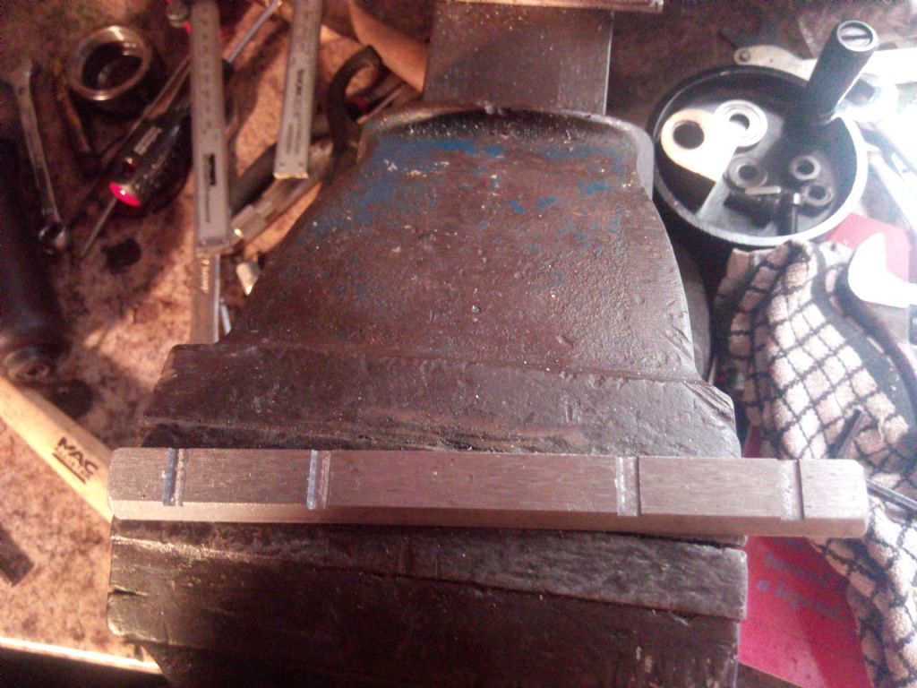
                                    Your comment: 'I noticed all the gib strips where not machined correctly for the gib screws , so I'll sort that before I put the table back on'

                                    My suggestion: make vertical slots where ever the dimples on the gib are. This will allow the grub screw to locate more easily in the slot rather than a dimple which may be higher or lower than the centre of the gib. If this fails, then you can consider re-drilling and tapping new holes in the casting, next to the original holes.. more in line with the centre of the gib.

                                    Your comment: 'But I'd imagine it still would not be as rigid as the solid column'

                                    The tilting column box section is between 4mm to 6mm thick. I designed and commissioned the fixed column, originally as a component to make the SX2P, which I wanted made. The fixed column is approximately 10mm thick box section. It was designed by me, drawn up by a wiz SIEG mechanical engineer-designer on some sophisticated CAD within 30 mins… then it took a further days convincing and negotiating with the GM, to make. So, the answer to your comment is – YES – the fixed column is rigid.

                                    Your comment: 'What can these little mills DOC be in steel and aluminium? With let's say a 4 flute 10mm end mill'

                                    The DOC is dependent on various factors, based on your motor/torque/hi/low gear in your case, feed, speed, cutter grade/quality/coated/un-coated, quality/grade of material being milled, with or without coolant, and finally what your expectations are. It is a process of experimentation

                                    Generally, I would start experimenting with 0.5mm depth for Steel, 1mm depth for Aluminium, checking the feel and finish, and then proceeding to deeper depths between 1 to 2mm for Steel and 2mm to 3mm for Aluminium, and so on, depending on factors mentioned above. For a more qualified idea, you would need to get a response from real users, such as Neil and Russel, who have similar or variants of SIEG mini-mills. Neils machine has the same motor as yours I think.

                                    Regarding the table end cover plate, although I have not come across your table version, if the right hand side plate is metal, then the left hand side will be metal.

                                    Ketan at ARC.

                                    #352860
                                    Ketan Swali
                                    Participant
                                      @ketanswali79440

                                      John M,

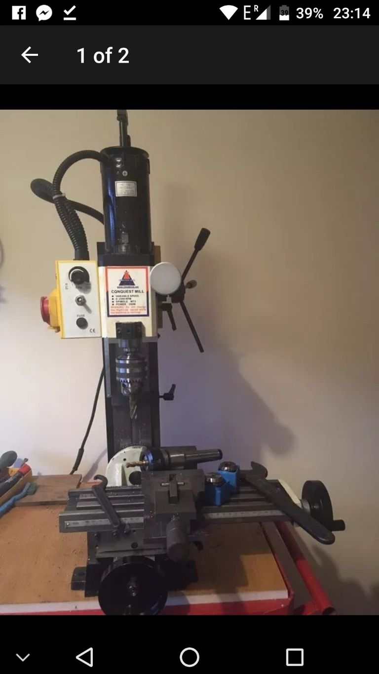
                                      Looking at the picture of your mill, I am not sure but it looks like you have a milling cutter held in a drill chuck. If this is the case then it is a bad idea holding a milling cutter in a drill chuck. If it is a drill bit which you are holding in a drill chuck, then my observation is retracted, and maybe I need new glasses. teeth 2

                                      Ketan at ARC.

                                      #352864
                                      Oldiron
                                      Participant
                                        @oldiron

                                        Hi John M. I have a Chester Conquest mill. It too has the bigger table on it. I have fitted a 2 pulley drive belt system. It works a dream and also gives the option of 2 speed ranges. The table end plate should be metal and contains a bush to hold up the lead screw. As for the column, I have had the machine since new and apart from resetting the vertical tram when I got it I have had no further problems of alignment with it. I might get to make a strengthening bracket one day. I have made a lot of items including 8 BXA tool holders and all the parts for my dividing head without any problems. BUT remember it is a small mill so be conservative with the cuts you take. I have used up to 20mm cutters despite all the comments across the web that this is not possible. It all depends on how you treat the machine as far as I am concerned. I have fitted mine with 3 axis DRO and power table feed & rev counter.

                                        All in all an excellent little machine but I do now have a larger mill for bigger jobs but the Chester is my go too machine for most things that I do.

                                        I agree with Ketan, do not hold cutters in your chuck when you have a collet chuck lying there

                                        regards

                                        Edited By Oldiron on 04/05/2018 22:34:12

                                        Edited By Oldiron on 04/05/2018 22:35:25

                                        #352868
                                        Dennis R
                                        Participant
                                          @dennisr

                                          Hi John M

                                          It appears from your picture that the ER collet chuck, with a milling cutter in, does not have the collet correctly inserted in the collet nut. If that is the case the collet will not self extract and the cutter may not run true.
                                          Dennis

                                          Edited By Dennis R on 04/05/2018 23:00:50

                                          #352877
                                          John Murphy 3
                                          Participant
                                            @johnmurphy3

                                            Ketan, again thank you for the lengthy reply , if I could take 1mm in steel I will be very happy. Regards the drill chuck and collect chuck. That is the pic that was used by the seller in the for sale add. I’ll post updated pics tomorrow and I’m aware of the basics with milling. I have an ML7 lathe in which iv done milling with. I was only able to take .2mm doc so if I’m able to take 1mm in steel that would be great. Ketan do ye sell those end plates on the tables? Old iron , by the sounds of it I’ll be very happy with this thank you for the info.

                                            #352888
                                            Ketan Swali
                                            Participant
                                              @ketanswali79440
                                              Posted by John Murphy 3 on 05/05/2018 02:23:29:
                                              Ketan, again thank you for the lengthy reply , if I could take 1mm in steel I will be very happy. Regards the drill chuck and collect chuck. That is the pic that was used by the seller in the for sale add. I'll post updated pics tomorrow and I'm aware of the basics with milling. I have an ML7 lathe in which iv done milling with. I was only able to take .2mm doc so if I'm able to take 1mm in steel that would be great. Ketan do ye sell those end plates on the tables? Old iron , by the sounds of it I'll be very happy with this thank you for the info.

                                              Fingers crossed on DOC. If you were able to take 0.2mm DOC on your lathe on steel, there could be various reasons, including grade of steel. Some grades of steel will mill better than others, but I would be the wrong person to ask about steel grades.

                                              ARC does not sell the end bracket/plate for your table. Have a chat with Tony at Chester and see if he can help you. Make sure you identify the table dimensions to him. Alternatively, ask Oldiron if he can send you details/pictures, and see if you can make one.

                                              Ketan at ARC.

                                              #352889
                                              SillyOldDuffer
                                              Moderator
                                                @sillyoldduffer

                                                John, you've mentioned a few times that you would like to take 1mm DOC in steel. The answer is yes, no and maybe.

                                                Ketan said:

                                                The DOC is dependent on various factors, based on your motor/torque/hi/low gear in your case, feed, speed, cutter grade/quality/coated/un-coated, quality/grade of material being milled, with or without coolant, and finally what your expectations are. It is a process of experimentation

                                                Generally, I would start experimenting with 0.5mm depth for Steel, 1mm depth for Aluminium, checking the feel and finish, and then proceeding to deeper depths between 1 to 2mm for Steel and 2mm to 3mm for Aluminium, and so on, depending on factors mentioned above.

                                                Good advice, but you always have to work within the limitations of your machine. Pushing too hard may result in tears! There's a clue in the name 'Mini-mill'. As milling machines go, it's at the small end, not designed or built to chew through metal at spectacular rates.

                                                The two key limitations are motor power and rigidity. Related to those are the risk of burning out the motor, or controller, or busting gears etc. when the machine is abused.

                                                As machine tools go, 350W isn't a lot of power when it comes to removing metal quickly. Even so, it's plenty powerful enough to damage the machine if the operator is excessively heavy handed. It will easily do a slow feed 1mm deep cut in steel with a small diameter cutter (you mentioned 10mm), but don't try it with a fly-cutter!

                                                Similarly, mini-mills (and hobby mills generally) aren't particularly rigid. They are not heavily built compared to a much more expensive industrial machine. Irrespective of motor power, DOC is limited by how much vibration the machine can absorb. That depends on a whole bunch of factors, not least how firmly the work can be held. (A low flat object bolted straight on to the table will take much heavier cuts than a tall wobbly thing held in a vice.)

                                                Ketan advised experimenting starting with light cuts. Although there are calculators I think that's the best way to approach hobby milling. Listen carefully to the machine and look at the results. When you get used to it, you can hear the difference between a machine working hard and a machine that's struggling. Inspecting the cut is invaluable too. If the finish is poor try adjusting cutter rpm, DOC, and feed rate to improve it.

                                                But my main point is that mills should be operated by surgeons, not butchers! This is particularly important when the tool is relatively flimsy. Becoming a surgeon will need study and practice; do you know about climb milling yet; have you tried it? JasonB is running a series on milling in MEW at the moment and this forum is good at answering questions.

                                                Nothing wrong with a mini-mill within it's limitations, but they have to be lived with. If your need is to remove large amounts of steel quickly, you need a much bigger machine.

                                                Dave

                                                Edited By SillyOldDuffer on 05/05/2018 09:50:42

                                                #352890
                                                Ketan Swali
                                                Participant
                                                  @ketanswali79440

                                                  +1 for what SoD said. He has explained it far better than I.

                                                  Ketan at ARC.

                                                  #352895
                                                  Oldiron
                                                  Participant
                                                    @oldiron

                                                    As SoD said "surgeons not butchers". I am very conservative in the depth of cut I take. I understand very well that my little mill is more ballerina than Hulk Hogan and therefore treat it as such. In steel EN8 or thereabouts I usually take a between 0.015" & 0.060" depending on the diameter and type of cutter I use. In Ali' I will take up to 0.100" also depending on cutter type & size. Its surprising how quick you can make a big pile of chips. If slab milling the side of a bar down the full flute length of a cutter you need to be a bit more conservative to prevent chatter. I find these parameters do all I need without over exerting me or the mill. If doing a lot of work , feel the motor and keep an eye on the temperature. If the motor feels too hot it is probably wise to slow down or stop for a while. After a long job I let the motor run at about 250 rpm for a couple of minutes so the fan can cool the motor down a bit. The mill will climb mill to give a really nice finish but only on very fine cuts. I have found that the usual feeds and speeds that are published in books etc usually apply to commercial machines and are far too much for a mini mill IMHO. I work my way up to what I feel the machine can do comfortably. I apply this method to all of my home machinery. I find tis method works for me, others may have their own different methods & I am sure you will soon get to know what your mill can or cannot do.

                                                    Any thing else I can help with just ask.

                                                    regards

                                                    Edited By Oldiron on 05/05/2018 11:52:13

                                                    #352921
                                                    John Murphy 3
                                                    Participant
                                                      @johnmurphy3

                                                      Thanks very much for the all the help guys , I milled slots in the gib strips and it helped quit a bit. Looking at the base of the mill it looks quite easy to make up an adapter to fit a solid column and I think that will be the route I will take after I use the tilting column for a while. 1525540337175.jpg

                                                    Viewing 25 posts - 1 through 25 (of 39 total)
                                                    • Please log in to reply to this topic. Registering is free and easy using the links on the menu at the top of this page.

                                                    Advert

                                                    Latest Replies

                                                    Home Forums Manual machine tools Topics

                                                    Viewing 25 topics - 1 through 25 (of 25 total)
                                                    Viewing 25 topics - 1 through 25 (of 25 total)

                                                    View full reply list.

                                                    Advert

                                                    Newsletter Sign-up