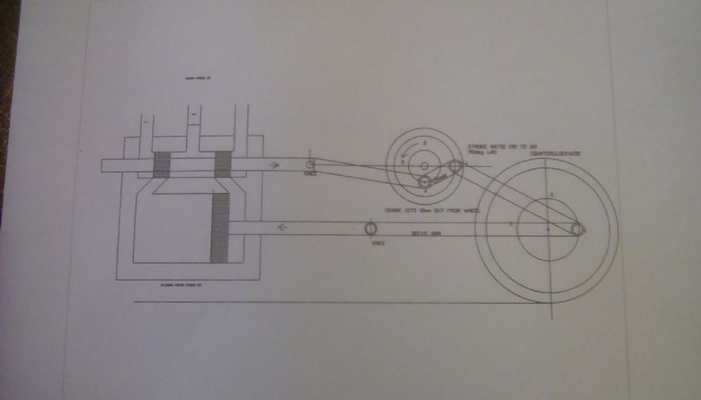
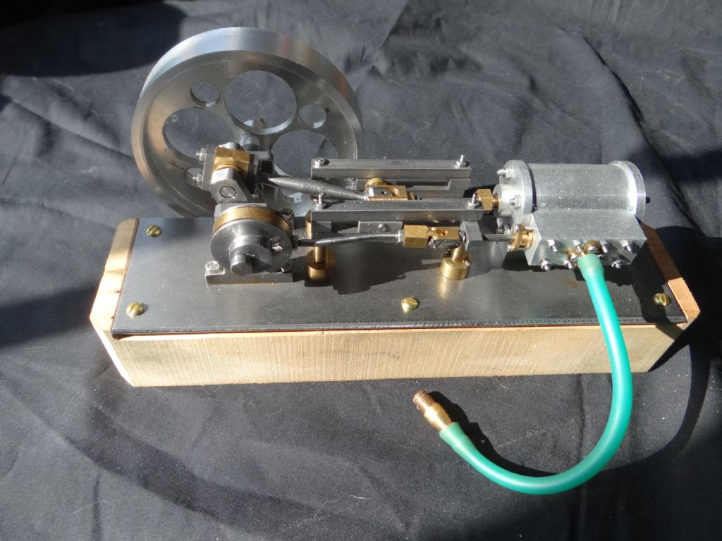
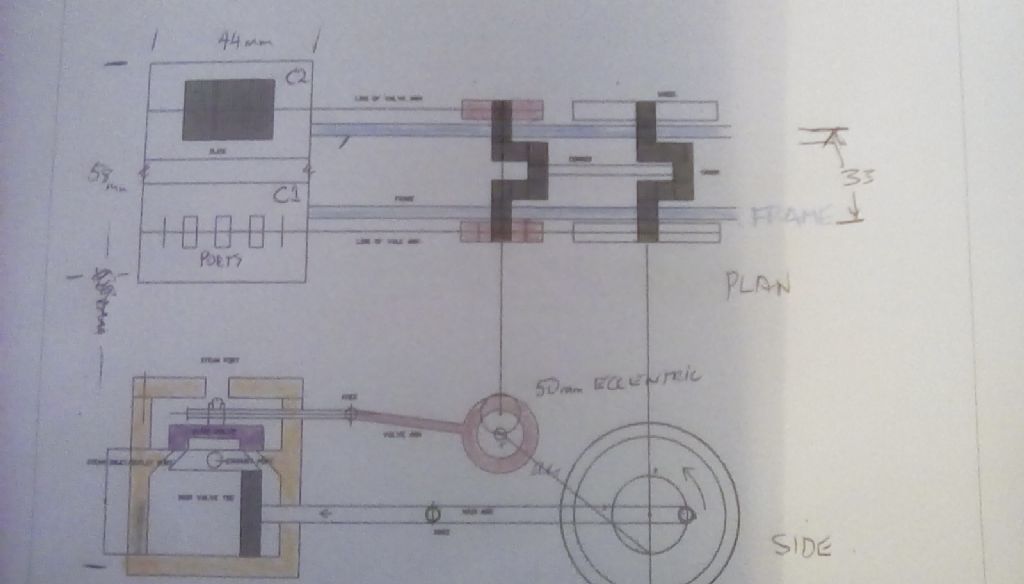
To amplify David Caunt's point, the valves should be just on the point of opening to admission as the crank passes through dead-centre. Large engines are made with a very small early opening called "lead" , but this a very carefully-calculated value, and not applicable in an application like this.
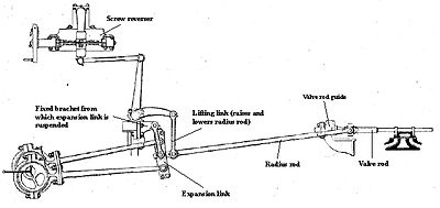
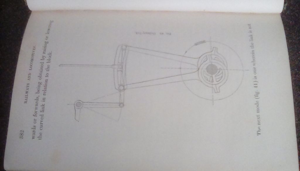
For reference I think the sorts of gear Brian G cites, with the vertical drive, are Hackworth and its Marshall and Bremme derivatives. They drive the end of the radius-rod in an ellipse whose horizontal component (not axis) gives the valve travel, and whose major axis angle sets the direction. Hackworth is common on small narrow-gauge locos, but needs quite a bit of headroom; and despite its apparent simplicity, like most valve-gears it requires careful setting-out.
Stephenson's Gear always has two eccentrics- one for each direction, essentially. That Gooch variant, and the Allan Straight-Link equivalent, differ only in adding links and joints, and fell by the track-side while the slightly simpler Stephenson's became so widespread on locos and traction-engines..
John –
Your " This does 4 things 1. Puts horizontal movement in line with valve chamber, 2 reduces main piston stroke length to valve stroke length. "
1) Good idea.
2) With respect I am puzzled by that. The valve travel is usually less than the (power) piston stroke.
For a simple engine with no lead, the maximum valve-travel V
= 2(lap + port opening)
in full gear. In Gauge 0 it's usual to be in either full or mid-gear anyway, no "notching up".
and in mid-gear, V = 2.lap
I.e the ports do not actually open, though the valve-gear moves them just enough to be on the edge.
By port opening I mean the maximum port opening to admit steam to the cylinder, and depending on design is not necessarily the port width. The valve closes at the cut-off set by your design, but I would think it no later than around 75%.
On the exhaust stroke the port is open to exhaust for virtually the whole of the piston-stroke, so the valve has no exhaust lap to speak of.
'
Looking at your drawing, the valve appears to have no admission lap. I could not enlarge it sufficiently to read the text without losing it in pixels, but I think I am right you are using inside-admission, as usual with piston-valves, so the valve is about to move right-wards. It shows both piston-valve heads line-on-line with both edges of their ports; so no lap. That will give a cut-off of 100%, so return very poor running for a lot of steam.
The two bobbins should be lengthened on their inner (inlet steam) sides, meaning at the engine's position shown the valve should be further to the right by that lap, not in its mid-travel as you've drawn. It would require the ports and bobbins both moving closer together to accommodate the extra travel in the same valve-chest.
(On locomotives the valve-chest is usually longer than the cylinder, but this to accommodate long-travel valves and direct steam-passages for fast running with heavy loads.)
'
I did write that lot aware you may already know some of it, but I hope it helps, and look forwards in due course to photos of the results.
Nigel Graham 2.


