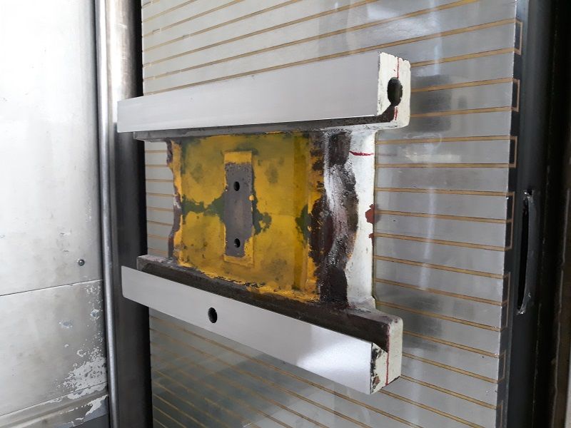
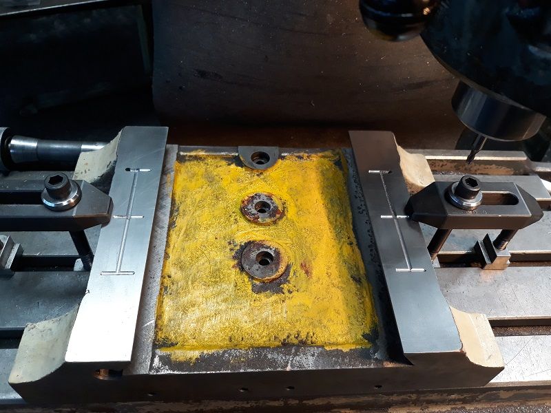
So I decided to add the oil grooves on the X Y sliding block of the ZX45 Mill Drill. After removing the main block, noticed that on the milling table it was not flat. Set it up on the surface plate at work and a rod in the Fixed dove tail slot. I then set about shimming it around until it looked as close to zero as I was going to get it. The rod was just a piece of centre less ground commercial hard chrome bar that fitted into the vee. Then I took the plate and it's corresponding shims to the surface grinder and did a minimum clean up. Then turned it over and ground the other side parallel. Then rechecked, to my surprise the other vee was within 0.01mm , so was happy with that. Total height change was 0.16mm off the stack height. Then went onto a mill and set about cutting the grooves for the oil supply feed, on the Y and the X axis. I drilled on an angle with a pistol drill to connect the oil gallery to the fitting(M5). Drilled 4mm diameter, then used a counter bore tool as a spotface tool. Then redrilled to 4.2mm for the M5 Tap, and used that to connect to the vertical drill hole. While set up on the mill, I milled across the end faces while it was dialed in. Then set up an angle plate, and drilled and tap M5 for options for mounting the scale for the DRO, and on the other end, just did the back leg M5 for mounting of a manifold/distributor block for the oiler. In the end, for the oil I just used a plate and did 2 circuits , one for the X axis, and one for the Y axis. Testing showed that gave a better supply with 2 separate circuits. Also added a centre M8 tapped hole for a table lock in between the current 2 gib locks. While having it apart, set the backlash on the nut to the leadscrews before placing them into place. Also replaced the thrust washers as they felt a bit rumbly on the handle.
I am happy with the results. Photo's are in the album as well. I always forget about pics until it is too late,.
Neil
Last side to be ground to a minimum cleanup.

Cutting the Y axis oil groves

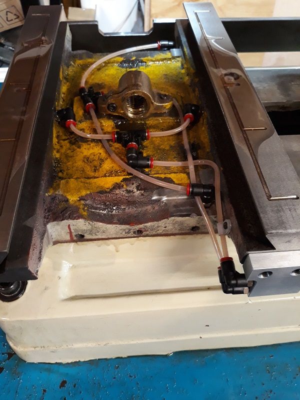
Ready for the top slide to be reinstalled, after already pre installed X axis and set the nut position on the bench. Then taken apart, fitted the tubing and fixed into position. Also tested the flows to see how even they were . Oil manifold is visible bottom rht, and across the top, can be seen the bar for holding the glass scale, with a cut out for the handle casting, and also has a cut out for the gib adjustment screw. The oil is supplied horizontally from an oil gun and used M6 grease nipples. The oil lines are 4mm Nylon with M5 thread fittings. Nylon can be bent with a bit of hot water to make it hold it's position/shape.

Douglas Johnston.


