3 -Phase Conversion of a Mini-Lathe

3 -Phase Conversion of a Mini-Lathe

Home Forums Workshop Tools and Tooling 3 -Phase Conversion of a Mini-Lathe

Viewing 21 posts - 26 through 46 (of 46 total)
  • Author
    Posts
  • #385937
    SillyOldDuffer
    Moderator
      @sillyoldduffer
      Posted by Ron Laden on 16/12/2018 10:56:23:

      This is a beginners question so dont shoot me down in flames. I guess you guys obviously looked into it before you started but it would make me wonder is a mini-lathe capable of handling all this extra power..?

      Ron


      Looking at the detail, the article isn't suggesting using much more powerful motors, just changing the type.

      Electric motors come in a bewildering variety of types, and not all are good for driving a lathe. Keeping it simple, in order of desirability:

      • Special to purpose AC motors with unusual wiring and control arrangements; some washing machines have them. Avoid because likely be hard to understand and get working.
      • Universal Motors as used on small sewing machine. Can be speed controlled but low power output and torque – OK only on a tiny lathe or small drill. Otherwise avoid.
      • Single Phase Motors – Compromise design to provide rotation from single-phase domestic supply. No speed control, moderate torque, low torque on start, bumpy output causing vibration. Not ideal on a lathe (or much else) but they work reasonably well, acceptable rather than good. Often fitted on rubber mountings to reduce vibration. Rather unreliable due to capacitors, centrifugal switches and extra windings needed to make them work.
      • DC Motors. Good speed control and torque/power characteristics. Low vibration. Main disadvantage is the brushes wear out and eventually the commutator. Rarely used on older lathes (apart from giants) because affordable control electronics weren't available before about 1975. Popping a mini-lathes control board comes up fairly often, but DC motors are a good choice on a mini-lathe and up to about 1200W on a small mill.
      • Three-phase Motors. No speed control, good power/torque characteristics, low vibration. Motors simpler, more efficient, cheaper, and far more reliable than other types. Huge disadvantage – the need for a 3-phase supply, and gearboxes/belts to adjust speed.
      • Three-phase Motors With VFD. Joy. All the advantages of three phase in a home workshop with a single-phase supply plus good speed control. Downside is the cost of the VFD, potential hassle setting it up due to multiple baffling options, and the risk the electronics might blow up. In practice VFDs seem reliable. Very popular on new machines above 1000W, because the VFD simplifies wiring safety interlocks as well as providing exceptional control facilities.
      • Brushless DC. Likely to be the best choice of all. Not really DC, rather a polyphase motor related to the 3-phase type that must be driven by a special electronic controller. Main disadvantage – still a bit pricey.

      When I had a mini-lathe, I would only have upgraded it had I written off the motor and electronics. The DC motor as fitted is well-suited to the machine, so like for like replacement is sensible. You might feel different if you happen to have a spare 3-phase motor and VFD to hand, or found that a 3-phase package was cheaper or more easily sourced than a replacement DC motor/controller set.

      I wouldn't go out of my way to replace a mini-lathe's DC motor with 3-phase just to improve it. Likewise, it would make more sense in theory to upgrade a Myford lathe's 'grotty' single-phase motor to 3-phase+VFD, but in practice Myford owners manage perfectly well with single-phase. It might be better in theory to convert, but doing so unless there's an actual improvement is just wasting time and money.

      Dave

      Edit : just saw the PS!  Putting more than 600W on to the spindle of a minilathe is overkill, 750W is probably the safe maximum.  Deliberately putting 2HP on a mini-lathe with the intention of using it would be insane! 

      Edited By SillyOldDuffer on 16/12/2018 11:59:52

      #385941
      I.M. OUTAHERE
      Participant
        @i-m-outahere

        The reason this lathe was set up with a VFD and 3 ph motor was because when I bought it off ebay it had been dropped off a forklift damaging the cross feed screw and gear cover , this meant it was used as a spare parts machine so it came with no motor or controller .

        The VFD cost the same as a replacement driver board and the motor was similar .

        Back then brushless motors were not around – well not on mini lathes anyhow , it was bought as a stuff around with it project in mind .

        #385960
        Neil Wyatt
        Moderator
          @neilwyatt
          Posted by XD 351 on 16/12/2018 11:30:34:

          i do intend to play with the belt tension of the poly v belt to allow some slip if i get to aggressive with the machine . I'm hoping that the weight of the motor will be sufficient for the v belt tension but I won't know that until i use the machine and this would also allow some slip if needed .

          I found that I needed to put a fair bit of extra tension on the belt, although this was exaggerated by the acute angle my tensioner works at.

          #385961
          Neil Wyatt
          Moderator
            @neilwyatt

            The arrangement with the Hoover motor was actually really nice to use although it needed an extra weight on top to stop slipping. I did miss having a speed below 200rpm though.

            Neil

            #386076
            I.M. OUTAHERE
            Participant
              @i-m-outahere

              Now that i have the motor bolted on and the v belt fitted i can see what you mean Neil ! I will have to make up some sort of arrangement to pivot the motor up to change speeds and i am thinking of using a mechanism similar to a car handbrake to lock the motor down and tension the belt .

              #386121
              Robert Atkinson 2
              Participant
                @robertatkinson2

                Reading the original conversion article, despite the abundance of safety warnings the system does not comply with basic electrical safety, machine safety or emissions requirements.

                Most importantly the "E" stop should break the input supply to the drive. This could be direct or via a no-volt release contactor wired to the LV stop. The latter is best as if there is no drive failure the drive will bring the machine to a stop faster than just cutting the power. You have to cut the power as well to cover for a drive control failure. A E stop on just a control input is not good enough.

                To comply with low voltage regulations (and common sense safety) this type of drive must be fitted inside a protective enclosure. The control panel wiring should use screened cable.

                To comply with emissions regulations the particular drive shown needs an external input filter. (the CUB inverters with an "E" suffix to the part number have a filter built in and come with an earthing plate) A good filter can cost as much as the drive. Technically you then have to get it tested for emissions before using it (yes even as a personal item). Testing may be a bit much, but a decent filter is essential.

                Not trying to stop people doing "DIY" but we should at least try to do things correctly.

                Robert G8RPI.

                #386137
                Neil Wyatt
                Moderator
                  @neilwyatt

                  The contactor suggestion is a useful one. I'm assuming you mean cut the mains power with a relay/contactor? Wil the unit still brake the motor to a quick halt if you cut the mains power?

                  It's not obvious from the photo but the thick green wire going to the control panel wire is an earth wire connected to the cable screen.

                  The EMC directive came into force in April 2016, the article was published in June 2014. It's not practical for us to revise all historic articles (there are thousands of them on this site if you include back issues).

                  Neil

                  #386152
                  Robert Atkinson 2
                  Participant
                    @robertatkinson2
                    Posted by Neil Wyatt on 17/12/2018 18:16:45:

                    The contactor suggestion is a useful one. I'm assuming you mean cut the mains power with a relay/contactor? Wil the unit still brake the motor to a quick halt if you cut the mains power?

                    It's not obvious from the photo but the thick green wire going to the control panel wire is an earth wire connected to the cable screen.

                    The EMC directive came into force in April 2016, the article was published in June 2014. It's not practical for us to revise all historic articles (there are thousands of them on this site if you include back issues).

                    Neil


                    Hi,
                    As long as the VFD has not failed it will continue to be powered by the DC "Bridge" capacitor and if the e-stop control input is active at the same time as the mains input disconnected the drive will go into dynamic breaking to stop as soon as possible. The energy in the rotating parts is actually dumped into the capacitor keeping it carged until it stops. Drives with very high inertia loads that have to stop quickly in normal operation have to have a brake resistor to dissipate the energy so the capacitor does not over charge.

                    I thought the green wire was a screen but it's not mentioned and not in the circuit diagram.

                    The current version of the EMC Directive may be dated 2014 but the original was 1989 and the law requiring comliance in the UK came into force in 1996.

                    Robert G8RPI.

                    Edited By Robert Atkinson 2 on 17/12/2018 19:41:30

                    #386158
                    Neil Wyatt
                    Moderator
                      @neilwyatt

                      Could you point me at a plain English guide to the EMC directive and DIY users?

                      I can't see any mention of end users in the Government guidelines.

                      http://www.gov.uk/government/publications/electromagnetic-compatibility-regulations-2016

                      Neil

                      #386209
                      Robert Atkinson 2
                      Participant
                        @robertatkinson2

                        Hi Neil,

                        I'll try to find a reference but most are for manufacturers and importers. The obligation for conformity happens when a item is put on the market or is first put into use. The VFD's despite having CE marks are components and only comply with the directives if the manufacturers instructions are followed. Generally this means filters, enclosures and safety devices. Having tested many items using VFDs and electrically similar servo drives, I can say that they won't pass without significant work. There is no dispensation in the EMC directive for one-offs or personal use. The only dispensations are for electronic development kits for professional use in R&D facilities and for radio amateurs. Note that you have to be compliant, you don't HAVE to test. I feel a reasonable hobby approach is to use filters and enclosures (for electrical safety under the low voltage directive) as recommended by the manufacturer. While machinery and LCD "failures" only put you and others in your workshop at risk (maybe neighbours if it catches fire), EMC can affect many services even some distance away. These include "safety of life" systems such as emergency services radios and aircraft navigation systems.
                        If there is an issue, you should at least be able to show some diligence.

                        Robert G8RPI CEng MRAeS

                        #386260
                        Neil Wyatt
                        Moderator
                          @neilwyatt

                          The difficult bit is not fitting a filter but knowing whether it is effective or not. the manual gives no guidance, it just suggest fitting 'a filter'.

                          At present an fm radio 50 cm from the inverter can't pick up anything. On am it picks up a modest hum audible up to about 15 metres away, but even close to the unit the signal is not strong enough to overcome a distant station.

                          I could set up my computer and SDR to see what broadband radiation there is. But there will always be something how can I tell if it's a problem or not?

                          I have hat I would consider a suitable filter, but at the moment it's built into something else (a PWM lathe speed controller of similar power).

                          Neil

                          Edited By Neil Wyatt on 18/12/2018 13:28:22

                          #386277
                          SillyOldDuffer
                          Moderator
                            @sillyoldduffer
                            Posted by Neil Wyatt on 18/12/2018 13:27:35:

                            I could set up my computer and SDR to see what broadband radiation there is. But there will always be something how can I tell if it's a problem or not?

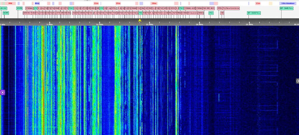
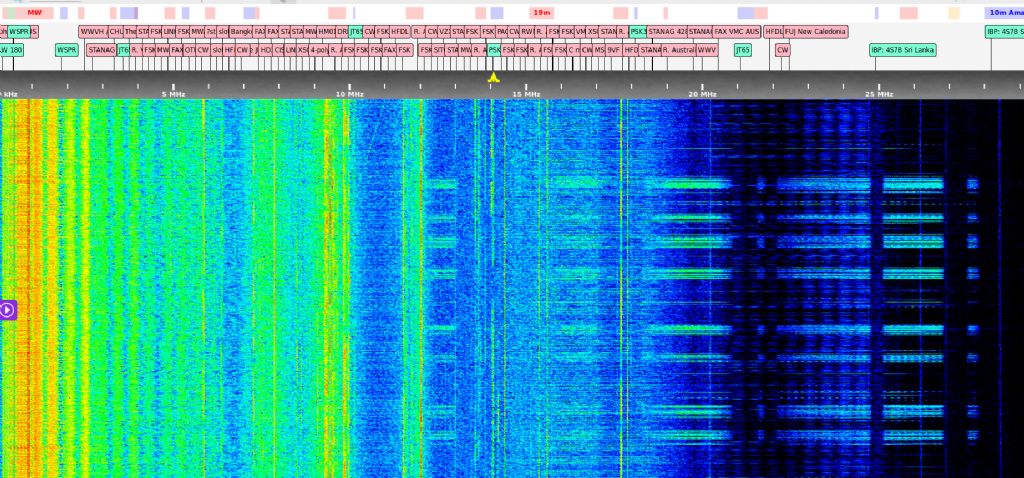
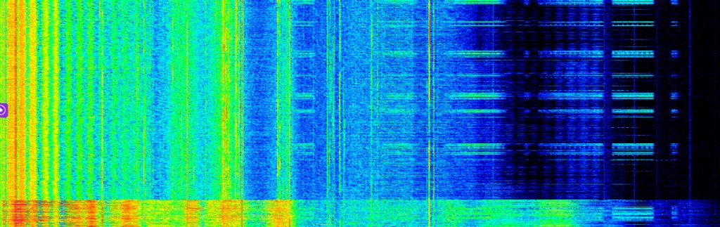
                            EMC problems are usually pretty obvious on a Software Defined Radio. I happen to be trying to sort a serious EMC problem out at the moment. Here's some screenshots from SDRs at a quiet location in Weston-Super-Mare compared with what I get in a noisy village about 40 miles away.

                            First. This is Weston's view of about 30 seconds worth of the entire radio spectrum from 0-30MHz. No signal is black, then with increasing strength up through white, green, yellow and red. Genuine signals are narrow vertical lines, noise tends to be broad. Most of the light blue in this screenshot is a mixture of man-made and natural noise. There's quite a lot of noise, but this is fairly good.

                            wsm_sw.jpg

                            In comparison here's what's received at my home:

                            sodnolathe.jpg

                            Note the almost total absence of man-made signals! My SDR is almost deafened by man-made noise. The horizontal lines most obvious on the right are Ethernet signals, probably leaking from an IP over Powerline system nearby. Much of the white fog is VDSL (Broadband Internet) leaking from telephone lines, probably because neighbours have unbalanced their feeds by fitting extension cabling inside their homes. (This also reduces download speed.) The wavy wide green, yellow and orange vertical streaks are caused by switch-mode power supplies – cheap ones are rarely well filtered.

                            A major problem living in a village is that all the power-lines are strung between poles. Any radio muck that escapes past a filter can be radiated by miles of cabling acting as a good antenna.  Most homes these days have some leaky electronics – if my home is typical about 90% of devices are fine, and about 10% are rogue.

                            The fun really starts when I turn on my lathe. The extra noise generated by the VFD is very obvious at the bottom of the screen.

                            sod_sw_lathe.jpg

                            I feel guilty about my noisy lathe. I improved it slightly last year by fitting well-screened cable between motor and VFD, but I haven't tried any filters yet.  When playing lathes I'm not listening to shortwave radio.

                            Domestic radios aren't good at detecting EMC issues – they're rather deaf, and sharply tuned to loud local broadcasts. If interference can be heard on an ordinary radio you have a major problem.

                            If you have filters please use them. Also avoid counterfeit and very cheap switch-mode power supplies. And if something's not in use, unplug it!

                            If you happen to own an SDR, it's worth checking what you can hear against an internet accessible SDRs, Try sdr.hu and websdr.org

                            Dave


                            Edited By SillyOldDuffer on 18/12/2018 14:57:38

                            #386363
                            Robert Atkinson 2
                            Participant
                              @robertatkinson2

                              Great post Dave.

                              Generally any filter is better than none. Make sure it is rated at a high enough current. Physically larger or higher current is generally better. Only fit to the input of the VFD. Do NOT fit a filter between the VFD and motor unless it is specifically designed for that drive and motor. Keep leads between the filter and VFD as hort and direct as possible. Ideally mount drive and filter in a grounded metal box or at least mount both filter and VFD directly on a metal (light alloy) plate. Keep leads between VFD and motor short too.

                              A Corcom 10EMC1 is a good example of a dual stage filter that will help a lot with noise from VFDs and is reasonably priced.

                              10EMC1 - Power Line Filter, Chassis, 10 A, 250 VAC, EMI, RFI, Quick Connect, 1.48 mH, 2.001 ?F

                              https://uk.farnell.com/corcom-te-connectivity/10emc1/filter-10a-1-phase/dp/9586474?st=power%20filter
                              I'd suggest this is the minimum for a small (<1hp) VFD.

                              Similar and probably slightly better performing is the Schurter 5500.2603.01

                              https://uk.farnell.com/schurter/5500-2603-01/ac-filter-1-phase-10a-250v/dp/2134492?st=power%20filter

                              Hopefully it's obvious that the filter needs to be in a box or otherwise protected from contact with persons or swarf.

                              Robert G8RPI.


                              Edited By Robert Atkinson 2 on 18/12/2018 21:51:59

                              #386764
                              I.M. OUTAHERE
                              Participant
                                @i-m-outahere

                                Here is the general arrangement of th belt tenshioner , nothing special just a sliding spring loaded block that locks into the grooves in the shaft . I still have to make a handle withthe mechanism to make pulling up the sliding block ( screwed to the end of the cap screw and is located in a slot in the main body ) . This arrangement also allows the motor to be locked forward so the belt is loose .

                                3d03d4df-ff0f-46fa-8ac2-9db68f618dc1.jpeg


                                b2e00e11-23db-4a3d-8123-0b826e213f0f.jpegc8f60815-a9ce-45b2-8e77-4fc54b5ef99f.jpeg

                                Edited By XD 351 on 21/12/2018 05:28:16

                                #386775
                                HughE
                                Participant
                                  @hughe

                                  When I fitted the VFD to my S7 I first tested the setup on the bench. The EMI was very obvious causing some electronic gadgets in the workshop to fail. I fitted the Schurter filter as identified by Robert and fitted the whole assembly in a shield diecast box. There are now no obvious EMI problems. Just received my SDR kit from BG , will try SODs tests when I have got it going .

                                  Out of interest in the latest EPE there is a 2 part article on making a speed controller for single and three phase motors.

                                  Edited By HughE on 21/12/2018 07:36:00

                                  #386792
                                  I.M. OUTAHERE
                                  Participant
                                    @i-m-outahere

                                    If all the above is true then there needs to be a dedicated thread for VFD interference issues because anyone wanting to use one on any lathe needs to be aware of this . There is no reason why you couldn't use the same set up shown with a dc treadmill motor . I am not trying to promote the virtues of a vfd set up , just show how i have done it and so that those who may be interested may gain some insight or ideas .

                                    With my ultrasonic cleaner i fitted  a  commercially available unit because one of the driver boards had failed and destroyed the inductor so  the  new filter covered all the boards . 

                                    When i was a kid i worked out  that a small dc motor running flat out would cause an interference stripe across the tele which drove my old lady mad especially when the daily soap opera was on – she never worked out what caused it otherwise I wouldn't be here .🤪 

                                    Edited By XD 351 on 21/12/2018 10:02:24

                                    #388205
                                    I.M. OUTAHERE
                                    Participant
                                      @i-m-outahere

                                      Just a quick update and photo of the enclosure , the rest of the upgrade is now just a put it back together affair so I won't bore you with that . I may be back later on with the tumbler gear modification once i work out how to do it ! a2a1cb15-a590-43c3-ad19-cbee11118ccd.jpeg

                                      #388239
                                      Neil Wyatt
                                      Moderator
                                        @neilwyatt

                                        Neat woodwork!

                                        #388261
                                        Niels Abildgaard
                                        Participant
                                          @nielsabildgaard33719
                                          Posted by XD 351 on 30/12/2018 08:05:20:

                                          Just a quick update and photo of the enclosure , the rest of the upgrade is now just a put it back together affair so I won't bore you with that . I may be back later on with the tumbler gear modification once i work out how to do it ! a2a1cb15-a590-43c3-ad19-cbee11118ccd.jpeg

                                          Cooling air for motor?

                                          #388382
                                          I.M. OUTAHERE
                                          Participant
                                            @i-m-outahere

                                            Cooling is via 12v automotive fan mounted inside the cabinet and the air is ducted up to the fan shroud of the motor , it then exits through a vent on the end of the motor enclosure. The fan is pwm controlled so i can set the airflow and this also keeps the fan a bit quieter as it doesn't run flat out . The vfd is also mounted inside the cabinet and the fan also gives some airflow for that as well .

                                            #391852
                                            I.M. OUTAHERE
                                            Participant
                                              @i-m-outahere

                                              c242c83f-bafe-473e-9c7b-b64f99ea2188.jpegb4a8b6a2-20b8-49ff-bd9e-c92d66254805.jpeg34ad223e-1e3e-4d94-a5de-e14a800578db.jpegdfda5381-2e18-4f34-8652-5e1138af6f46.jpegb64abb06-617f-4db3-9bbb-110630eab2e5.jpeg0882045c-0d76-4faf-b4c9-893361c594f5.jpegHere is the mod for the tumbler gear – nothing spectacular but it works although neutral is a problem for some reason – maybe because the tumbler gears are odd sizes I don't know . There is so little clearance to work with so even though i have extended the linkage of the tumbler bracket ot still bunches up towards one side of the movement .

                                            Viewing 21 posts - 26 through 46 (of 46 total)
                                            • Please log in to reply to this topic. Registering is free and easy using the links on the menu at the top of this page.

                                            Latest Replies

                                            Viewing 25 topics - 1 through 25 (of 25 total)
                                            Viewing 25 topics - 1 through 25 (of 25 total)

                                            View full reply list.