Building the simple Henry Muncaster steam plant

Building the simple Henry Muncaster steam plant

Home Forums Beginners questions Building the simple Henry Muncaster steam plant

Viewing 12 posts - 1 through 12 (of 12 total)
  • Author
    Posts
  • #807882
    half whit
    Participant
      @half-whit

      Hi All,

      I am planning to make the two cylinder oscillator shown in the two diagrams. I have a similar vertical boiler which I will build into the model.

      I don’t anticipate too many problems in the build but I  am puzzled by one aspect of the design. The text from the author (Muncaster) specfies a crankshaft supported at each end by a pair of pedestals. This can be seen in 1/2 plan view of the engine. The center of the shaft approx 1″ long and 5/16″ diameter is unsupported. Why? This looks all wrong to me, but am I  missing something. Maybe something in the dynamics of the engine?
      <p style=”text-align: right;”>Geoff20250719_090025</p>

      #807886
      JasonB
      Moderator
        @jasonb

        It’s a lot easier to get a crankshaft running between two bearings than three, particularly given the equipment that the average beginner back in 1912 would have had.

        I also doubt that those little cylinders are going to put serious load into the shaft. Think about the high speed enclosed twin engines like the Stuart MTBs and Sirius all twin cylinder with no central support and they were good for 4500rpm and worked under load.

        #807889
        Michael Gilligan
        Participant
          @michaelgilligan61133

          Given this gem of an understatement … I would think even two bearings might present a challenge to some in the original cohort of builders !

          .

          IMG_0905

          .


          Assuming you have the tools and the skill to get it all aligned … adding a third bearing seems a valid improvement.

          MichaelG.

          .

          Edit: Maestro Jason beat me to it

          #808058
          half whit
          Participant
            @half-whit

            Hi

            Thanks for the replies.  On reflection the crankshaft does look robust and would survive without a central pedestal.  I may cut apertures on each side of the platform leaving an area to fit an optional  “aesthetic” pedestal.

            From muncasters text I assume the cranks will be set at 90 to each other which with D/A cylinders will give a self starting engine?

            Is there any other reason why the cranks are set at 90?

            Cheers geoff

            #808061
            Nigel Graham 2
            Participant
              @nigelgraham2

              Not only starting.

              The 90º crank-setting was normal for twin-cylinder steam-engines, to aid starting in use albeit making balancing in manufacture, more difficult.


              Its other reason was to give more even torque per revolution.

              The maximum torque from one cylinder comes around mid-stroke, during the minimum, dead-centre, point for the other.

              Since the engine is both double-cylinder and double-acting the resultant torque approaches some constancy through the full 360º: a polar plot of effort against angle looks a bit like a four-leafed clover. The flywheel inertia smooths the curve to some extent, making such engines very good for driving directly-coupled dynamos and similar duties.

              #808080
              half whit
              Participant
                @half-whit

                Wow Nigel,

                That’s a great post, details expressed perfectly.

                I sensed the 90 degree cranks setting had something to do with better engine dynamics but couldn’t put in to words like you have.

                Thanks again

                Geoff

                #808120
                Julie Ann
                Participant
                  @julieann

                  Apart from making the engine self starting having the cranks at 90 degrees doesn’t increase torque. What it does do is spread the torque impulses around the circle. First, consider that the rotational inertia of the flywheel means that the flywheel is essentially a lowpass filter with respect to torque impulses on the crankshaft.

                  With the two cylinders in sync there are two impulses per revolution. With the cranks at 90 degrees there are four (smaller) impulses per revolution. Given that the impulses are smaller and there are double the number (double the frequency) the flywheel is more effective at ironing out the torque fluctuations.

                  Julie

                  #820136
                  half whit
                  Participant
                    @half-whit

                    Hi All,

                    When I started this thread my plan was to eventually make the engine and power it from a small Vertical boiler.

                    I have now started building the engine and it’s coming on ok.

                    I would like to post some progress reports but first would if possible like to change the name of the thread. Can this be done? I can’t work out how.

                    Moderators can you do it? I would like ” Building the simple Henry Muncaster steam plant”

                    Many thanks Geoff

                    #820153
                    JasonB
                    Moderator
                      @jasonb

                      Consider it done, looking forward to seeing some progress.

                      #820325
                      half whit
                      Participant
                        @half-whit

                        Hi All again,

                        Well the build log for this engine starts now, I do hope it is of interest. I have made a small number of Muncaster engines including the single cylinder D/A engine which is a forerunner of this two cylinder model.

                        I have a small vertical boiler for the engine which will need commisioning and will then be a dedicated part of the steam plant.

                        Ok, cylinders first, these are fabricated with a cast iron cylinder, a brass port face and a small bronze stub pivot. After some simple turning and boring on the lathe the cylinder was transferred to mill and rotary table to shape the waste. The other parts are all bonded in place with JB Weld adhesive.

                        In the second photo, using the Sherline to true up the port face and the pivot stub.

                        The valve block is much the same as the one shown in the drawing, with port channels milled front and rear and each side linked at a mid point in the channel.

                        More to come in due course, probably bi-weekly, must get it finished for christmas, well that’s the plan!!  Geoff

                        20250812_122304Screenshot_20251014-152404_PhotosM20251014_151000

                        #825541
                        half whit
                        Participant
                          @half-whit

                          Hi All,

                          I’ve been setting up the boiler for this engine over the last few days.

                          I bought this boiler on the internet from the ali express site earlier in the year.

                          The safety valve has a very light spring which means it is a low pressure boiler. not sure what that is but I would guess between approx. 2-3 p.s.i., but that easily powers the small engines I have and will I’m sure be ok for this twin cylinder one.

                          I have done some modifications to make it look more traditional which includes a copper cowl support and a bronze/ copper flue. It’s also been converted to gas fired instead of the alcohol burner and I’ve added a simple Stan Bray type regulator. Also planned is to route the copper supply pipe down the outside and then inside the copper cowl, looping20251121_112512 
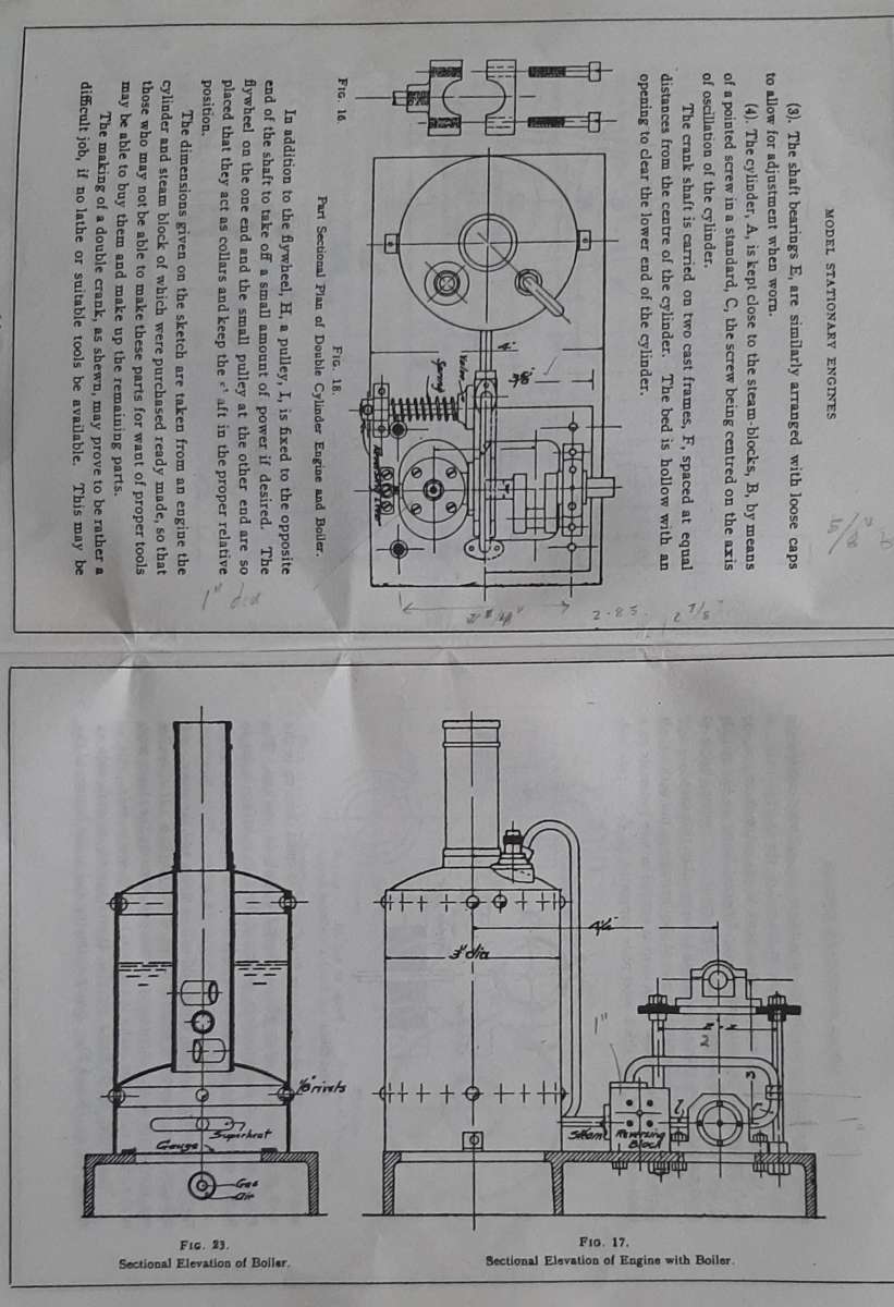
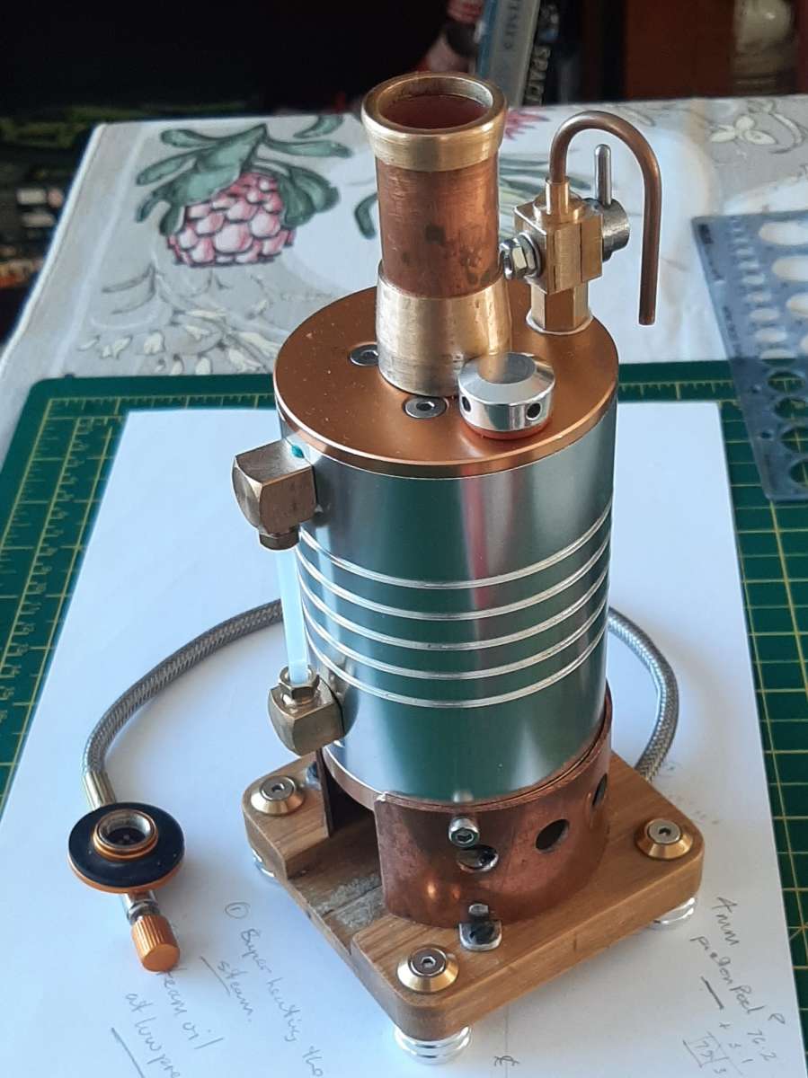
around the gas flame and then back out to the engine (same as the muncaster engine, superheating? ).

                          Engine is coming on (slowly), progress reports in due course

                          Geoff

                          #828641
                          half whit
                          Participant
                            @half-whit

                            Hi All,

                            Well I had plans to finish this engine for Xmas but not now, however it’s coming on slowly. Photos show a partial assembly with the base, cylinders, valve block and pivots all in place. Its also all pistoned up, if you’ll pardon the expression!

                            Each piston has viton o ring which certainly adds something,  feels good. Would probably be OK without the ring, but why not, a perfect job for the sherline

                            Have good Xmas All geoff20251213_13243420251213_131033

                          Viewing 12 posts - 1 through 12 (of 12 total)
                          • Please log in to reply to this topic. Registering is free and easy using the links on the menu at the top of this page.

                          Latest Replies

                          Home Forums Beginners questions Topics

                          Viewing 25 topics - 1 through 25 (of 25 total)
                          Viewing 25 topics - 1 through 25 (of 25 total)

                          View full reply list.