I'm planning on making a die filer and wanted some advice on how to manage the eccentric.
I have a Paralux motor with a DC speed control which runs at 150rpm max. I plan to gear that up to a max of 3 or 4 times that which should cover the speed range.
My main target is small things like crossing clock wheels, but I would like to be able to handle slightly heavier work if need be. So one of the requirements I think I have is to be able to adjust the stroke (clock files short stroke, 9 inch bastard a bit longer).
I've looked at various designs (and made some up) and would appreciate any input on which would be the most robust and reliable.
Please be aware the sketches are just to get the idea across. there will need to be a bit more design!
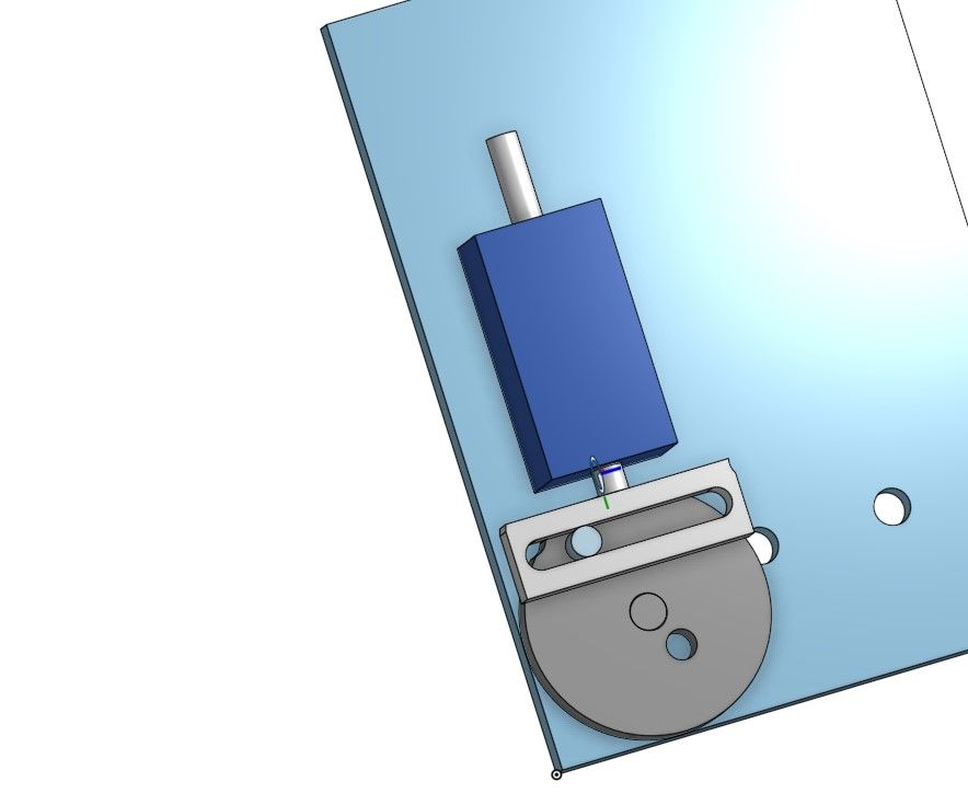
This is one of the simplest. A wheel with a button on which pushes the slotted bur up and down. Several holes in the wheel to allow different strokes.

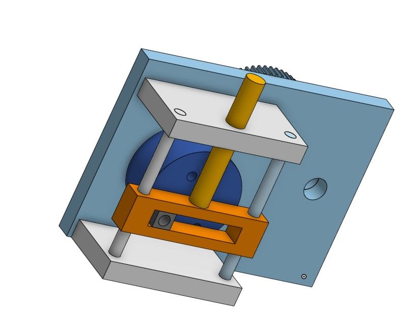
The next one is the same basic idea but the button runs into a bearing which pushes the containing bar up and down.

I saw that one in a youtube build and wondered if the point was to reduce or spread the wear.
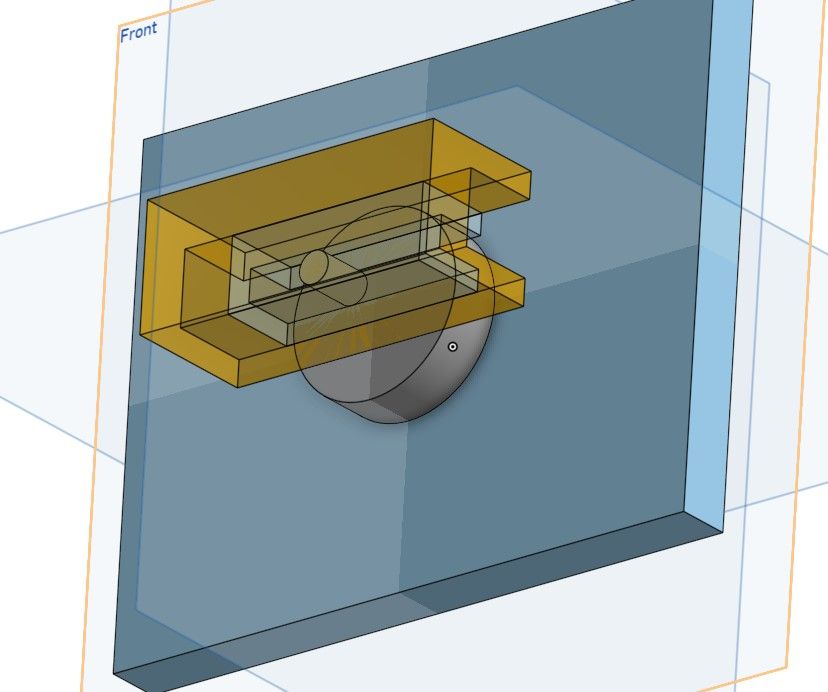
Finally, and this is my own idea.
In this case the axle is offset from the centre of the wheel. I thought that I could mill a flat on the end and remove the wheel and replace in alternate square holes.

I think some of the commercial units (or kits) follow a design like the above, though only with one stroke and the wheel probably permanently mounted on the axle.
Oh – my first thought was to build something a bit like a steam engine eccentric, but that adds a lot of height/length and would be more complex than the ideas above.
I hope this makes a bit of sense and all suggestions and advice welcome!
Iain
 JasonB.


