Class 2 Standard 2-6-0 5G by Don Young

Advert

Class 2 Standard 2-6-0 5G by Don Young

Home Forums Locomotives Class 2 Standard 2-6-0 5G by Don Young

Viewing 13 posts - 1 through 13 (of 13 total)
  • Author
    Posts
  • #117657
    Kim
    Participant
      @kim

      The Don Young drawings in particular the combination lever, radius rod and piston valve have had some of the dimensions changed with no margine date or authorised amendment on the sheets concerned, this issue was taken up with Reeves who have no ability or desire to help, I also have the LLAS construction manual wich use the original dimensions.

      I decided to follow the revised dimensions on these 3 items and completed the motion gear but finding it difficult setting the valves, before I pull all my hair out is there any one who has built this model that could advise the correct dimesions to make it work or any other info that might help

      Advert
      #1172
      Kim
      Participant
        @kim

        Valve Gear Dimensions

        #118152
        nick feast
        Participant
          @nickfeast85472

          I'll be interested in this too as I have a part built model which came with all the valve gear made up except the eccentric rods. I made them 'to the job' to give an equal swing of the expansion links to and fro relative to the valve operating (radius) rod. This worked out at 4.785" instead of the 4.8125 called for on the drawing. Not sure this will make much difference, what problems are you having?

          If it ever gets finished it will be an Ivatt 2-6-2 tank, it should feel at home with all the Q1's in the workshop!

          Nick

          #118276
          Kim
          Participant
            @kim

            Bearing in mind this is my 1st 5G loco with piston valves so have limeted experience , having followed Dons manual instructions on setting the valves and trying other meathods, testing on copressed air I cannot get the motion to turn through a complete revolution, it seems as if the valve needs more travel to clear the ports, so before I start looking at any major adjustments I need to know the dimesions I have worked to are correct . My drawing has 4.937" centres (check to place) on the eccentric rods?

            Kim

            #118317
            Sub Mandrel
            Participant
              @submandrel

              Hi Kim,

              Don't forget the valves will cut off before full stroke. No problem on steam as expansive working will push the piston to the end of the stroke. This doesn't happen with air, so it won't run smoothly at low speed on small amounts of air. Try LOTS of air at a good pressure before ssuming a fault.

              Neil

              #118360
              Kim
              Participant
                @kim

                Neil, Thanks for responding and the suggestion, I have a compressor with capcity of 24Ltr air reciever @ 80psi, would have thought that would create enough volume/pressure ?any other comments or thoughts would be apprecated.

                #118365
                Sub Mandrel
                Participant
                  @submandrel

                  That should be plenty…

                  Have you tried the old expedient of blowing down the tubes whilst rotating the wheels so you can tell when the valves actually open and close?

                  Neil

                  #118379
                  61962
                  Participant
                    @61962

                    Kim,

                    You seem to be worried about the length of the radius rod, but if that isn't quite right, the engine should still run. The combination lever should ideally be at right angles to the valve centre line when the piston is at its centre of travel and the gear is in the mid position. This isn't essential though and some full size engines had vertical combination levers even though the cylinders were inclined. If your engine won't run in full gear you need to check the geometry of the gear. Is the return crank set correctly? Is the eccentric rod the right length. Any error here will put the valves out of phase and give them longer or shorter or skewed travel, but again, unless the error is gross then the engine will run.

                    I would suggest this. Block the driving axleboxes in the running position. Find the dead centres of both cylinders accurately. I assume you know how to do this but ask if you don't. With one of the cylinders on front or back dead centre wind the gear from full forward to full back gear. If the geometry of the return crank and eccentric rod are correct there should be no movement of the valve. Put the cylinder on the other dead centre and check again. There should be no movement of the valve. Do the same for the other side. If its not right then make an adjustable eccentric rod and use it to determine the correct length and make new eccentric rod(s). If the errors are small you might be able to lengthen or shorten them with the help of some heat and a bit of force as they did with full size locos, but it's not so easy with small ones.

                    Once you have it sorted remove the valves and find the distance between the exhaust edges of the ports. Check the exhaust edges of the valve heads are the same distance apart. Make sure the valve heads are all the same length. Correct any errors. Measure the distance of the exhaust edge of the port from the front of the valve chest. Replace the valves and with the gear set in in the mid position and the piston in its mid position (i.e. when the opposite side is at a dead centre) set the exhaust edge of the valve in line with the exhaust edge of the port. Do the same for the other side. Now see if it will run.

                    It should run in full gear without being lumpy. If it is check there are no tight spots. Usually these are associated with quatering, axlebox centres and rod length, but could be pistons fouling cylnder ends, or crossheads fouling slide bar ends.

                    Once you have it running and bedded in you can think about setting the valves with a little more finess, but the basic setting above should suffice to get you going.

                    Best of luck

                    Eddie

                    #118476
                    Kim
                    Participant
                      @kim

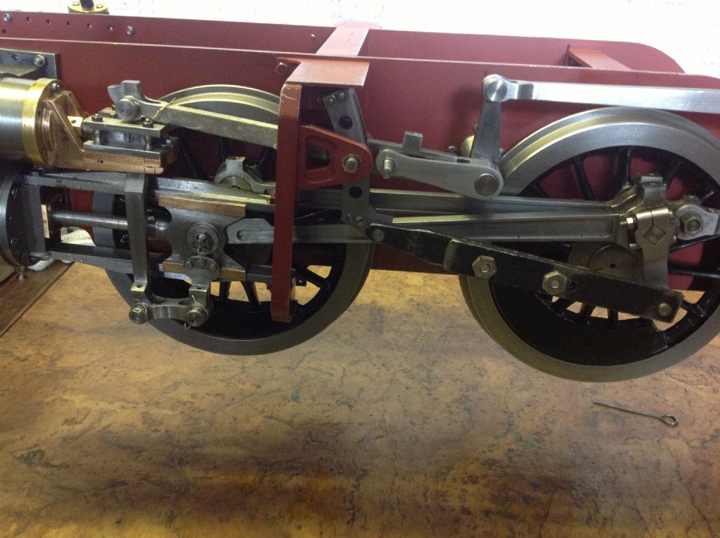
                      image.jpgEddie,thanks for all your comments,since my original posting I have through other enquiries established the drawings I've worked to are correct so it looks like an error some where on my part. The shot shows the motion set with the piston set at the centre of its travel? You mention finding dead centres on the cylinders and say if I'm not sure ask, to be sure I'm doing everything correct an you clarify this procedure please,as you can see I've made an adjustable eccentric rods so they will be easy to amend the size if required.

                      Kim

                      #119397
                      61962
                      Participant
                        @61962

                        Kim,

                        OK finding the dead centres.

                        From the driving wheel centre put a mark on the frame that is half the diameter up and half a diameter back and lightly centre punch. It doesn't need to be exact you could do it by eye, it's just a reference point.

                        Turn the wheels in the forward direction until the crosshead is as far forward as it will go, and then continue the rotation until the crosshead is 1/4 to 3/8ths back. Scribe a mark on the slidebar at the front of the crosshead. With a pair of spring dividers set at about half a wheel diameter (it's as well to set this to an exact dimension and make a note of it for future reference) scribe an arc across the face of the driving wheel tyre using your frame reference point as centre. Rotate the wheels back past the dead centre and bring the front of the crosshead back to your mark on the slide bar. Scribe another arc. Put a centre pop on each of the arcs a small distance in from the edge of the wheel. Using another set of dividers bisect the distance between the two arcs and centre pop at the same distance in from the edge. Rotate the wheel and using your first set of dividers set the centre pop mark at that distance from the mark on the frames. The piston is now exactly at it's front dead center.

                        Using the same reference do this for the back dead centre. I suggest you reference the slide bar mark to the front of the crosshead again. Do the whole process on the other side.

                        You should now be able to accurately determine the eccentric rod lengths.

                        Hope you can follow that.

                        Regards

                        Eddie


                        Edited By 61962 on 10/05/2013 21:59:59

                        Edited By 61962 on 10/05/2013 22:00:52

                        #119408
                        61962
                        Participant
                          @61962

                          Kim,

                          OK finding the dead centres.

                          From the driving wheel centre put a mark on the frame that is half the diameter up and half a diameter back and lightly centre punch. It doesn't need to be exact you could do it by eye, it's just a reference point.

                          Turn the wheels in the forward direction until the crosshead is as far forward as it will go, and then continue the rotation until the crosshead is 1/4 to 3/8ths back. Scribe a mark on the slidebar at the front of the crosshead. With a pair of spring dividers set at about half a wheel diameter (it's as well to set this to an exact dimension and make a note of it for future reference) scribe an arc across the face of the driving wheel tyre using your frame reference point as centre. Rotate the wheels back past the dead centre and bring the front of the crosshead back to your mark on the slide bar. Scribe another arc. Put a centre pop on each of the arcs a small distance in from the edge of the wheel. Using another set of dividers bisect the distance between the two arcs and centre pop at the same distance in from the edge. Rotate the wheel and using your first set of dividers set the centre pop mark at that distance from the mark on the frames. The piston is now exactly at it's front dead center.

                          Using the same reference do this for the back dead centre. I suggest you reference the slide bar mark to the front of the crosshead again. Do the whole process on the other side.

                          You should now be able to accurately determine the eccentric rod lengths.

                          Hope you can follow that.

                          Regards

                          Eddie


                          Edited By 61962 on 10/05/2013 21:59:59

                          Edited By 61962 on 10/05/2013 22:00:52

                          #119419
                          61962
                          Participant
                            @61962

                            Kim,

                            OK finding the dead centres.

                            From the driving wheel centre put a mark on the frame that is half the diameter up and half a diameter back and lightly centre punch. It doesn't need to be exact you could do it by eye, it's just a reference point.

                            Turn the wheels in the forward direction until the crosshead is as far forward as it will go, and then continue the rotation until the crosshead is 1/4 to 3/8ths back. Scribe a mark on the slidebar at the front of the crosshead. With a pair of spring dividers set at about half a wheel diameter (it's as well to set this to an exact dimension and make a note of it for future reference) scribe an arc across the face of the driving wheel tyre using your frame reference point as centre. Rotate the wheels back past the dead centre and bring the front of the crosshead back to your mark on the slide bar. Scribe another arc. Put a centre pop on each of the arcs a small distance in from the edge of the wheel. Using another set of dividers bisect the distance between the two arcs and centre pop at the same distance in from the edge. Rotate the wheel and using your first set of dividers set the centre pop mark at that distance from the mark on the frames. The piston is now exactly at it's front dead center.

                            Using the same reference do this for the back dead centre. I suggest you reference the slide bar mark to the front of the crosshead again. Do the whole process on the other side.

                            You should now be able to accurately determine the eccentric rod lengths.

                            Hope you can follow that.

                            Regards

                            Eddie


                            Edited By 61962 on 10/05/2013 21:59:59

                            Edited By 61962 on 10/05/2013 22:00:52

                            #119982
                            Kim
                            Participant
                              @kim

                              Eddie, thanks again for the information it's been most helpful in enabling me to successfully get the loco turning over on c/air, with the help of your suggestions and a small adjustment to the off side crank it seem to have solved my problems so that's great news and again many thanks to you all those members who contributed to the forum.

                              Kim.

                            Viewing 13 posts - 1 through 13 (of 13 total)
                            • Please log in to reply to this topic. Registering is free and easy using the links on the menu at the top of this page.

                            Advert

                            Latest Replies

                            Home Forums Locomotives Topics

                            Viewing 25 topics - 1 through 25 (of 25 total)
                            Viewing 25 topics - 1 through 25 (of 25 total)

                            View full reply list.

                            Advert