water gauges

Advert

water gauges

Home Forums Locomotives water gauges

Viewing 14 posts - 1 through 14 (of 14 total)
  • Author
    Posts
  • #405069
    duncan webster 1
    Participant
      @duncanwebster1

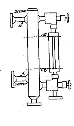
      The Australian boiler code has a clause stating …..Hollow columns or pipes providing a connection between water and steam pipes shall not be used . Any antipodean reader care to hazard a guess as to why? Does this only apply when gauge glass is mounted remote from boiler on long pipes? Full size GWR locos had the water gauge proper mounted off a column which itself was connected to the boiler, and they seemed to work OK

      ref AMBSC issue 7 clause 5.3.2

      Advert
      #1806
      duncan webster 1
      Participant
        @duncanwebster1
        #405236
        Paul Lousick
        Participant
          @paullousick59116

          Duncan,

          I do not have a copy of AMBSC issue 7 (Copper boilers) but do have a copy of issue 4 for Steel boilers which has a similar statement.

          water column.jpg

          I talked to our model club inspector who explained that the water gauge had to be connected, totally independent of any other take-off to the boiler. In some installations the column could be connected by a couple of pipe bends which could possibly give a false water level reading even though it has been done on older installations. (they also had professional boiler designers).

          The original drawings for my boiler has the water gauge connected to a steam manifold at the top which was also used to feed the injectors. It is not allowed because changes in pressure when the injector is used causes a false water level reading and amateur operators may not be aware of the problem.

          Paul.

          #405243
          Simon Collier
          Participant
            @simoncollier74340

            The sentence doesn't make a lot of sense. To me it implies that you can't have another connection between top and bottom fittings apart from the glass, but why would you?

            #405244
            Martin Johnson 1
            Participant
              @martinjohnson1
              Posted by Paul Lousick on 16/04/2019 01:42:54:

              water column.jpg

              I talked to our model club inspector who explained that the water gauge had to be connected, totally independent of any other take-off to the boiler. In some installations the column could be connected by a couple of pipe bends which could possibly give a false water level reading even though it has been done on older installations. (they also had professional boiler designers).

              The original drawings for my boiler has the water gauge connected to a steam manifold at the top which was also used to feed the injectors. It is not allowed because changes in pressure when the injector is used causes a false water level reading and amateur operators may not be aware of the problem.

              Paul.

              Clause 5.4.3 makes perfect sense and the friction losses of another offtake can make the water reading false – no problem with that.

              However, if that clause is satisfied, I am with Duncan in that what possible difference could GWR style columns make? So we are actually no nearer to answering the "why?"

              Martin

              #405266
              FMES
              Participant
                @fmes

                I wonder how 5.4.3 affects the positioning of the upper water gauge fitting on the Simplicity roller – the top tapping is fitted to the lower part of the cylinder which connects directly into the steam space between the boiler and the cylinder, leading to the regulator.

                #405313
                Paul Lousick
                Participant
                  @paullousick59116

                  Not sure of size of boiler on Simplicity roller. This code does not apply for boilers having a design pressure of less than 250 kPa (36 psi), a barrel diameter of less than 100mm {4"}  and a water capacity of less than 1 litre.

                  I am not familiar with a GWR style water column. Anyone have a photo/drawing ?

                  Paul

                  Edited By Paul Lousick on 16/04/2019 13:41:51

                  #405325
                  FMES
                  Participant
                    @fmes
                    Posted by Paul Lousick on 16/04/2019 13:35:31:

                    Not sure of size of boiler on Simplicity roller. This code does not apply for boilers having a design pressure of less than 250 kPa (36 psi), a barrel diameter of less than 100mm {4"} and a water capacity of less than 1 litre.

                    I am not familiar with a GWR style water column. Anyone have a photo/drawing ?

                    Paul

                    Edited By Paul Lousick on 16/04/2019 13:41:51

                    Paul,

                    The boiler is approx 30" long x 7" diameter running at 90psi for a 41/2" scale engine, so would apply I guess, and a standard design.

                    #405327
                    Nick Clarke 3
                    Participant
                      @nickclarke3

                      This is a generic picture of a column water gauge from the internet. LBSC described one in his 'Live Steam Book'

                      water gauge.jpg

                      I suspect the passageways are harder to keep clear/more likely to block up.

                      #405331
                      Nigel Graham 2
                      Participant
                        @nigelgraham2

                        Does seem odd.

                        I can understand why the gauge would use independent steam and water connections; and why the connections should be direct – as explained. In fact all the designs and engines I have seen – full-size and miniature – follow those two principles.

                        However there is no obvious reason why the water and steam connections cannot be linked, unless such designs have given rise to odd problems of their own. It would be very unusual, but some full-size boilers, especially in very large plant installations had such a column as part of an automatic shut-off that operates if the glass breaks.

                        I have consulted The Good Book… aka Handbook For Railway Steam Locomotive Enginemen, (typesetting was cheaper in them thar days) pub. British Transport Commission, 1957.

                        This shows the normal gauges with glass and three test-cocks, but also shows a type with a pipe behind the glass, and with two test-cocks in that. A note, "Copper Firebox Backplate", on the cross-section of fitting and mounting, suggests GWR. Crucially, this pattern also has a ball-valve in the water fitting below the glass, so I assume this too, is an automatic shut-off, though the text does not say so.

                        If anything a parallel water column might ease oscillations in the glass as the water in the boiler sloshes about, but on its own, not part of a safety device, would make no difference at all to the gauge-glass' action. In which case it's a needless complication.

                        I can't help thinking the restriction in the Code is more "not invented here guv'", than serving any real purpose.

                        #405334
                        SillyOldDuffer
                        Moderator
                          @sillyoldduffer

                          As chief plonker I know just enough about building boilers to be a menace! I feel the paragraph is directed at ignoramuses like me rather than experienced builders.

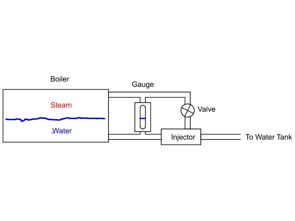
                          If I was making an engine, I'd be tempted to reduce work by making use of existing piping to plumb in a water gauge. Something like this, replacing two holes in the boiler with a pair of easy T-junctions:

                          badpipes.jpg

                          After engaging brain, I believe putting a water gauge across steam and water pipes also connected to something else is asking for trouble, whether it be an injector, pump, whistle or whatever. My example would show the water level correctly until the injector valve was operated, at which point I suspect the gauge would go haywire. It relies on pressure being balanced across top and bottom, and any other functions connected to the same pipework are liable to disturb that.  Another flaw in my design, if the injector valve leaked steam, it would tend to reduce the pressure at the top of the gauge causing it to read high.   How bad a misreading would depend on the diameter and length of the pipe, but it's dicky compared with doing the job properly.

                          Quite likely the author was thinking of me…

                          Dave

                          Edited By SillyOldDuffer on 16/04/2019 16:27:30

                          #405353
                          duncan webster 1
                          Participant
                            @duncanwebster1

                            Dave, I think the next clause covers this (see post from Martin Johnson above). I'm talking about the set up shown by Nick Clarke, with the column being hollow. I've emailed the Chairperson of the AMBSC to see if they can shed any light.

                            #405366
                            Martin Shaw 1
                            Participant
                              @martinshaw1

                              I believe the Australian code may have come about due to the possibility of scale or sludge forming in passageways that could potentially impact on the gauge reading without the operators ability to clear all passageways by a blow through. A guess maybe but instinct suggests that may be right. What I do know from full size locomotive experience is how much the gauge glass reading can be altered from the true state by whether the regulator is open or not, it can be somewhat disconcerting to watch your half glass disappear into the bottom nut when you shut off.

                              Regards

                              Martin

                              #405369
                              Nigel Graham 2
                              Participant
                                @nigelgraham2

                                Clarifying my post above:

                                After posting it I looked again at the diagrams in the book, and realised I'd missed the function of the two cocks in the column behind the glass.

                                They are not for clearing and testing the sight-glass but are water-level try-cocks, so if the gauge broke it was still possibly to verify the water is around the right level.

                                Once realising that, the whole thing became clearer.

                                The ball-valve below the glass would be driven shut if the glass broke, preventing the escape of water and making it safer for the driver or fireman to isolate the broken tube from both water and steam by the normal cocks. The column would still be open to the boiler, allowing testing water-level by the try-cocks.

                                +++

                                The sketch found by Nick Clarke might have been an attempt to copy the auto-closing pattern without really understanding it; but more likely it was to lower the bottom fitting to give a better length of visible glass in a gauge designed for small boilers. LBSC may have used it for some of his locos because he designed mainly 3.5" and 5"g locos with limited water-level ranges and cramped backheads.

                                Why not simply place the water bush lower? A good question, the answer probably lost in model-engineering history!

                                I certainly agree with Nick on the cleaning problem it gives.

                                I wonder if it's designs like that one which the Boiler Code is really against.

                                +++

                                SillyOldDuffer – yes you are right. Making the gauge glass share boiler connections with fittings like injectors, as in your diagram, will almost certainly give the problems you surmise. That's why it's not done!

                              Viewing 14 posts - 1 through 14 (of 14 total)
                              • Please log in to reply to this topic. Registering is free and easy using the links on the menu at the top of this page.

                              Advert

                              Latest Replies

                              Home Forums Locomotives Topics

                              Viewing 25 topics - 1 through 25 (of 25 total)
                              Viewing 25 topics - 1 through 25 (of 25 total)

                              View full reply list.

                              Advert

                              Newsletter Sign-up