Tramming in x direction BF-20 Mill.

Advert

Tramming in x direction BF-20 Mill.

Home Forums General Questions Tramming in x direction BF-20 Mill.

Viewing 12 posts - 1 through 12 (of 12 total)
  • Author
    Posts
  • #25614
    mrbuilder
    Participant
      @mrbuilder

      How would this be possible?

      Advert
      #326153
      mrbuilder
      Participant
        @mrbuilder

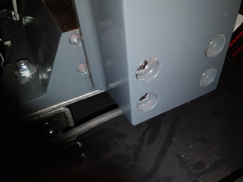
        Anyone know how it might be possible to correct the column alignment of my BF-20 mill (in the X direction)?

        A bit different to a SIEG which has the bolts at the base where this has the four bolts horizontally. Any ideas?

        img_20171109_191215.jpg

        Y is easy by shimming, but is okay on mine anyway after checking with a machinists square. X needs work hence the question.

        #326157
        Clive Foster
        Participant
          @clivefoster55965

          Simplest way is to enlarge three of the holes so the column can be appropriately shifted by pivoting about the unmodified hole. If necessary add a spacer to take up any clearance around the pivot bolt so the column can only rotate about it. Becomes a nightmare job if the rotation fulcrum isn't stable. Once correctly set drill through the column and into the base for a locating pin. Officially such a pin should be a taper type but a tight fitting parallel pin will do fine. Put a tapped hole in it or leave proud with an external thread so you can get the pin out if need be.

          Its more work and requires longer bots but adjustment is much easier if you also make the counterbores significantly oversize to take top hat form spacers with hexagon ends. Drill three suitably eccentric to accommodate the movement and one concentric for the pivot. Fit the concentric, pivot, spacer to one bolt and one eccentric one diagonally opposite. Nip up so the column is stiff to move and use the eccentric spacer as a cam to get the position right. Fit the other two eccentric spacers and do their bolts up tight before finally tightening the adjuster and pivot bolts. Obviously the spacers need to be a close running fit in the counterbores. No need for a pin as the top hat spacers hold things in place.

          Before starting work its prudent to draw things you to see how much movement in which direction you need to make provision for.

          Clive.

          Edited By Clive Foster on 09/11/2017 10:10:12

          #326215
          Tim Stevens
          Participant
            @timstevens64731

            I suggest it would also be prudent to make a plate or a sticker adjacent to these four bolts showing what mod has been done and which is the 'master' (concentric) top-hat spacer. If you get the job right, you may not need to work on these screws for a long time, and no-one remembers everything for ever. And the next owner will bless you.

            Cheers, Tim

            #326355
            I.M. OUTAHERE
            Participant
              @i-m-outahere

              If the alignment is done with just 4 bolts it would move around all over the place , maybe some alignment dowels in there somewhere ? If there are no dowels you should be able to loosen the bolts a little then tap the top of the column across to align it , this is what i had to do with the head of my x2 mill as the head casting is 2 piece and the column tilts – ideally after the alignment is done fit some taper dowels .

              Just out of curiosity how did you ascertain that the column is tilted ?

              Ian

              #326361
              Russ B
              Participant
                @russb

                Sorry if this a bit pushy, but here's what I'd do and indeed what I did on my own BF-20….. it's not a quick fix, but it's a good thing to know.

                Tram the tilting head to the table with a dti, to ensure she's not rotated left to right.

                Tram it front to back, to see if she's tilting forwards or backwards.

                Great, lets, say it's perfectly square – you now have two useless pieces of information, relative only to an arbitrary reference because you've assumed your dovetail column is perpendicular in two planes AND you've assumed the rotating circular surface of the vertical saddle is also square in two planes……. (or you used an engineers square, and assumed or accept the inaccuracy of your square/surfaces/measurements) – often with machines of far eastern origin, if they're not square at every step of the way and they don't mind. They just grind a bit off (usually off one single bit) here and there to get the final figures – as soon as your start raising and lowering the head, or rotating the mill head, you're assuming things move square and true, and they probably dont.

                Best not to assume anything these days.

                so let's go back a step and try to derive accuracy, assuming only reasonable things. Remove the table from the equation, forget it exists for now, so dont worry about that bolted connection . You now have a column, a saddle with a 360 degree surface, and a spindle axis. Its not unreasonable to assume your column dovetail was machined in a single pass and is pretty much square and true, if you've got a micrometer you could check it's parallel, but I don't think you'll gain much.

                Imagine now, that this column is laid down in front of you, with the spindle box on the left, as a lathe would be setout. (forget the table exists, remove it from your imagination). Now, you have a lathe without a saddle for a tool post, but who's spindle box can rotate on its own saddle.

                To check this rotating face is parallel in two planes, isn't easy, since right and left, you have no column, no reference, and probably isn't necessary unless you're attempting to split the atom in your shed (it's been done…..) but you can check it in one plane ((THIS IS OPTIONAL, NICE TO KNOW KINDA THING)), along the axis of the column. Simply move the saddle to centre, and mount a DTI in the spindle. Rotate the spindle box 360 degrees, taking 4 measurements as you pass the lower face of each dovetail – making sure you don't move the guage.

                assuming you're 360 saddle is true….. move on.

                now check out rollies dads method of spindle alignment, you can adjust very easily to align it towards or away from you (imagining it's laid down like a lathe) – however if you're spindle is pointing up or down along the axis of the "bed" (again, imagining its a lathe) – this is a more serious issue, it means the alignment of the quill bore, is knackered – the only option is to remachine the circular face on the back to correct the up/down movement – if it's out in the other plane…. it doesn't actually matter that much (imagine it being mounted on a hinge like a door, opening and closing, it doesn't matter where it swings, so long at it's not dropping or lifting along the axis of the column……)

                still with me?

                no, me neither………

                so if you successfully determined that your 360 rotating face, is square, and you've determined that your quill isn't pointing towards or away from column, then you can now go back to square one (almost)

                "Tram the tilting head to the table with a dti, to ensure she's not rotated left to right.

                Tram it front to back, to see if she's tilting forwards or backwards."

                You can't tram left and right to the table, because you don't know if your spindle is aligned to the column unless you've just done the rollies dads method to alight the spindle left/right. So now when assuming you've done that, when you "Tram the tilting head to the table with a dti, to ensure she's not rotated left to right." – the difference is – if you're out, it's the column that's out, and not any errors in the alignment of the rotating spindle box or the trueness of the 360deg spinning face.

                The only accuracy you're accepting, is the spindle runnout – which can easily be quantified – you actually already have all the measurements you needed to know from the rollies dads method, so you can acutally offset then values and incorporate this – but seriously, this is getting silly, but its there if you want perfection, 

                I'd consider that a mechanical QED (almost)….. now, if you still need that shim, you know you're not offsetting an error in your spindle to column alignment………

                that was taxing……. I'd started writing an article for the magazine but I'm a long way from home right now, so don't have it…. this is all off the top of my head, but I think this is right, I spent quite a while working this out – the measurement and checks are actually simple in the end if you think about it……..

                Edited By Russ B on 10/11/2017 08:18:56

                #326362
                Russ B
                Participant
                  @russb

                  I just editied that to add a missing step, so if you've just read it, and this post wasn't already underneath, I apologise the edit started 2/3rds of the way down…..

                  I might have to edit it again, but it's now Friday beer'o'clock on my side of the world – and since its 34c and blazing sunny, I'm off to slap on some sun cream and head to the beer garden !!

                  #326452
                  Neil Wyatt
                  Moderator
                    @neilwyatt

                    First fit a bar in the chuck and lock the spindle if possible.

                    Use a DTI and set the tilt so that you get no motion of the needle regardless of whether you move just the quill or the whole head up and down the column.

                    This gets quill and column perfectly aligned.

                    You can now check, and adjust if necessary, the column using normal tramming tests (e.g. dti in the spindle).

                    You can't easily set the column unless the head is aligned first.

                    Neil

                    #326755
                    mrbuilder
                    Participant
                      @mrbuilder
                      Posted by XD 351 on 10/11/2017 07:02:39:

                      If there are no dowels you should be able to loosen the bolts a little then tap the top of the column across to align it , this is what i had to do with the head of my x2 mill as the head casting is 2 piece and the column tilts – ideally after the alignment is done fit some taper dowels .

                      Thanks. I was able to get it to under a 0.001" by tapping the column, I also thought of this shortly after and it worked for me.

                      Posted by XD 351 on 10/11/2017 07:02:39:

                      Just out of curiosity how did you ascertain that the column is tilted ?

                      By using a machinists square, but yes of course there are some assumptions made by using this method.

                      Posted by Neil Wyatt on 10/11/2017 13:33:49:

                      You can't easily set the column unless the head is aligned first.

                      How so, I'm not sure I understand this? I've always though of these as separate checks, how does the head out of alignment affect a check on the column?

                      Posted by Russ B on 10/11/2017 08:11:05:

                      Sorry if this a bit pushy, but here's what I'd do and indeed what I did on my own BF-20….. it's not a quick fix, but it's a good thing to know.

                      Thanks heaps for this wealth of information! I am indeed keen to know and I'm going to run through your method / checks once I get a bit more spare time.

                      Cheers guys.

                      Edited By mrbuilder on 12/11/2017 02:46:48

                      #326756
                      I.M. OUTAHERE
                      Participant
                        @i-m-outahere

                        I use a pretty simple method to align the column ,

                        Set up a dial indicator on a mag base and clamp it to the side of the head ( not in the spindle ) then set up an angle plate on the table and square it up so the vertical face is at 90 deg to the x axis ( use an engineers square for this ) you can then use the indicator to sweep the vertical face of the angle plate .

                        Lock the X and Y axis up then take a reading by moving the head up and down the column , compare the reading at the top with the one at the bottom of the angle plate , don't wory about what it shows when you are raising or lowering the head as it will wander all over the place so just use the reading at the top and bottom of the angle plate and lock the gibbs up at each reading to remove any play between the column and head .

                        Once you are happy that the column is square to the table you tram the spindle in the normal manner .

                        You can use the same method to check if the column is tilted forward or backward just set up the angle plate parallel to the X axis .

                        #326757
                        mrbuilder
                        Participant
                          @mrbuilder

                          Yeah that's basically the same method I use to align the column but use a machinists square instead of an angle plate. And I use a (knock off) "indicol" to attach the DTI. Readings do indeed vary a bit on the way up or down as you've mentioned.

                          That test doesn't matter if the head is out, and what I'm not understanding about Neil's note about being hard to align the column without aligning the head first.

                          #326960
                          Russ B
                          Participant
                            @russb
                            Posted by Neil Wyatt on 10/11/2017 13:33:49:

                            First fit a bar in the chuck and lock the spindle if possible.

                            Use a DTI and set the tilt so that you get no motion of the needle regardless of whether you move just the quill or the whole head up and down the column.

                            This gets quill and column perfectly aligned.

                            Neil

                            Neil, you missed "if your lucky" inbetween the words quill and column……….and you also just assumed the spindle is running true inside the quill……..

                            Check the 360 saddle is true on the XZ plane, as described (or by any other means) if this is true to the XZ plane (aka front face of the column) – move on and check the quill is parallel by extending it, and mounting a dti on the column and then run the milling head up and down dialing in the column left to right (nice and easy its a rotating head after all) but also front to back (hand scraping or machining required – not so easy!!) 

                            once you've got or know the quill is true to the column in the XZ plane and XY plane as above, and you know you're 360 face is also true, only then can you start making assumptions as bold as suggesting the spindle, inside the quill, the mating between the quill and 360 face, and the mating between the face of the 360 and dovetail attaching it the column are ALL in alignment……. and you're still not 100% because you've still not check that the spindle inside the quill is running true, and this is where rollies dads method comes in to play.

                            For the record, my 360 face was ok on the vertical saddle, but the spindle was out of alignment. I went for the quick option as you suggest here Neil and it came back to bit me, every time I moved the Z axis, I drifted off the X,Y co-ordinate because I'd assumed my quill, and the spindle inside that quill were both true to the column – silly silly mistake. The spindle inside the quill was slighty out, but no big drama, the quill however was pointing towards the column! So if I shimmed the column to get the spindle level to the table, the Y co-ordinate would drift as I wound the head up and down.

                            Check all this once, and use the machine for life, and take neat little shortcuts as you suggest, with confidence.

                            Edited By Russ B on 13/11/2017 13:04:58

                          Viewing 12 posts - 1 through 12 (of 12 total)
                          • Please log in to reply to this topic. Registering is free and easy using the links on the menu at the top of this page.

                          Advert

                          Latest Replies

                          Home Forums General Questions Topics

                          Viewing 25 topics - 1 through 25 (of 25 total)
                          Viewing 25 topics - 1 through 25 (of 25 total)

                          View full reply list.

                          Advert

                          Newsletter Sign-up