Tolerance for needle bearings?

Advert

Tolerance for needle bearings?

Home Forums General Questions Tolerance for needle bearings?

Viewing 12 posts - 26 through 37 (of 37 total)
  • Author
    Posts
  • #422406
    Michael Gilligan
    Participant
      @michaelgilligan61133
      Posted by Gary Wooding on 03/08/2019 10:50:20:

      Hi Michael, I'm not interested in being right, I just want to make a device that works, so I'm open to all suggestions .

      In order to reduce the overhang as much as possible I designed the roller assemblies to be symmetrical; all 13mm basic diameters with cheeks or flanges as guides. The "jockey" rollers don't actually do anything except help guide the seat. The axles were originally 8mm diameter. By "proper" bearings I assume you mean ball bearings. I thought of that but was advised that ball races with an OD of 13mm wouldn't withstand the expected forces – that's why I thought of needle rollers.

      Unfortunately, increasing the diameter of the rollers increases the overhang of the seat relative to the upright guidance rails.

      .

      What I had in mind, Gary, was something like hard skateboard wheels … but I didn't want to suggest any specific item, size, or proportions.

      For what it's worth: I built a device in about 1972 that used the geometry that I am suggesting, and it worked beautifully. [Note: mine was dead-weight counterbalanced, and lifted by hand; so I have contributed nothing to the discussion about threads]

      MichaelG.

      .

      https://www.warehouseskateboards.com/help/Skateboard-Wheels-Buying-Guide

      Edited By Michael Gilligan on 03/08/2019 13:43:04

      Advert
      #422423
      Gary Wooding
      Participant
        @garywooding25363

        Ian, I'm not convinced that two screwed rods would make the seat any more stable than the pairs of rollers that surround the uprights, as shown in the picture. Am I wrong?

        I've removed the parts that obscured the view.

        lift4.jpg

        #422424
        Robert Atkinson 2
        Participant
          @robertatkinson2

          For that application look at the track rollers I linked to in my earlier post

          https://www.bearingboys.co.uk/SupportYoke-Track-Roller–1724-c

          I also think you need two back braces either wire, rod or tube, one on each side to stop the frame twisting.
          While I know Remap provide liability insurance, how do they deal with CE marking? As a powered lift for human this arguable comes under a whole raft of legislation. I'm not saying don't do it, just curious.

          Robert G8RPI.

          #422425
          Robert Atkinson 2
          Participant
            @robertatkinson2

            I don't think two screws are automatically better and you would have to use toothed belts (or encoders and feedback if you are of an electronic bent) to keep them syncronised.. One thing to consider is rollers or bearings of some sort on the outside faces of the frame. unless the weight is exactly centered the moving part will try to tilt sideways and as there are just flat plate it will lock up. The don't have to take the same load as the main rollers.


            Robert G8RPI

            Edited By Robert Atkinson 2 on 03/08/2019 15:36:23

            #422426
            larry phelan 1
            Participant
              @larryphelan1

              Not sure if this will be of any help, but here goes anyway :

              Some time ago ,I built a workshop hoist after the style of one made by Dave Fenner some years ago.

              This design made use of U shape sections for the uprights, with the rollers within the frame and the table/seat overhanging to one side. This unit uses a wire rope winch to raise the table but there is no reason why it might be power driven. My hoist seems to work quite well although the rollers are just plain bar.

              The main point is that the support sections do not flex in any direction even under 50kg loads.

              I do not claim that this is my idea, but it might be worth looking at. I think there is a picture of it in my album

              #422427
              Clive Foster
              Participant
                @clivefoster55965

                Michael makes an excellent point about skateboard rollers. Readily available, proper bearings, more than up to the load and all the pesky details sorted so they just work.

                Size isn't an issue if you narrow the seat bit slightly so the back portion sits inside the frame. Plenty of room for wheels then.

                Your drive system appears to show the motor at the bottom with the screw working in compression. Wrong way round as it will try to buckle giving a bending / whipping effect that will send nut friction through the roof. The screw must be hung from a bearing at the top so its in tension. Bearing needs to be fairly free and the nut in a pivot so it all takes up its natural position. Look at the old style car "plug in the sills" side-jack. Engineering standards are applied crudity really but they lift half a ton with no great trouble.

                The original EasyRizer used a simple Allthread screw of similar dimensions to what you are using and was frequently demonstrated with a Honda Gold Wing perched on it running up and down under drive from a fairly ordinary, albeit good make, battery screwdriver. If yours has so much friction that it won't lift a person you have some serious fundamental design issues.

                I'd scrap the "door frame" and go for a single column with two triangulated braces back to the rear foot extensions. Picture shows the guide roller end of a hydraulic lifter rated for something over half a ton on a platform similar to, but rather larger than a person seat. Perhaps approaching double the effective overhang.  Weight limits set by the hydraulic pressure and base details not column & guides.

                Main tube is 2" by 3", axle pins are about 3/4" diameter on approximately 5 1/4" by 4" centre. Rollers are about 1 1/4" diameter with a 2" (ish) flange on one end. The other flange is free running. No significant side to side wobble when loaded although flanges just barely don't touch the main tube.  I imagine there is reason for one flange on the roller and one loose.  All steel. Made to rusty industrial "keeps on going" standards. The actual lift is between the lift guide tube and the platform. A top hung screw would work just fine. That one has a simple vertical hydraulic cylinder in a tube which connects the top of the hydraulic rod to the guides and platform. Tube also protects the rod when extended. For a screw version simple overlapping covers would seem more than adequate to keep things out of the works

                hoist rollers.jpeg

                Always remember being told many years ago when struggling to make one of my genius ( aka stoopid) ideas work "When your are in hole stop digging and copy something." Advice I was young and hung ho enough to ignore at the cost of a weeks worth of spare time to end up with less than stellar, albeit more or less functional, results.

                Clive


                Edited By Clive Foster on 03/08/2019 15:43:46

                Edited By Clive Foster on 03/08/2019 15:45:23

                #422584
                duncan webster 1
                Participant
                  @duncanwebster1

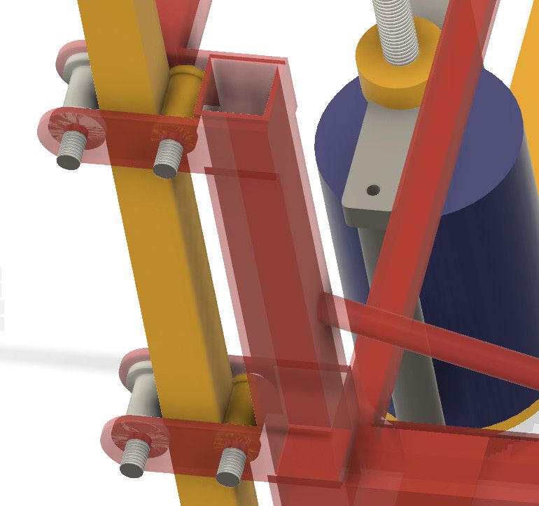
                  I might be misreading the drawing, but there looks to be 4 rollers. I'd have expected there to be a roller on the seat side at the bottom, if not then the seat is skidding on the pin, you need rollers on the seat side at the bottom and the back at the top

                  You can get cam follower bearings which have a thick outer race for this type of application. In my previous life I used to design lifting equipment. As it's for REMAP, if you want any sums doing/checking give me a shout

                  #422593
                  Michael Gilligan
                  Participant
                    @michaelgilligan61133
                    Posted by duncan webster on 04/08/2019 18:55:57:

                    I might be misreading the drawing, but there looks to be 4 rollers. I'd have expected there to be a roller on the seat side at the bottom, if not then the seat is skidding on the pin, you need rollers on the seat side at the bottom and the back at the top

                    .

                    I read it as eight rollers, Duncan [but perhaps I was wrong]

                    … Significantly, however, I think we reached the same conclusion as to what is needed.

                    MichaelG.

                    #422624
                    Gary Wooding
                    Participant
                      @garywooding25363

                      There are eight rollers – 4 on each side. I've made the seat semi-transparent to make them easier to see.

                      lift5.jpg

                      What are cam follower bearings and what sizes are available.

                      Incidentally, I intended to use two needle bearings to replace each of the four Delrin bearings that actually take the load – the Delrin ones are 20mm wide and the needle ones are 10mm.

                      #422625
                      Robert Atkinson 2
                      Participant
                        @robertatkinson2

                        Cam followers are similar to the track rollers I liked to previously but typically have a slightly crowned otter surface

                        **LINK**

                        Have tried applying load to the sides and front edge of the seat to see if you are getting some kind of locking up? A load directly on the cross member with the nut will tell if it's the screw that the issue.

                        Do you have a proper thrust bearing at the bottom of the threaded rod?

                        If you can put an ammeter in series with the motor that will give you a direct indication of the motor torque and you can see the effect of putting the same load in different places.

                        Robert G8RPI.

                        #422629
                        Michael Gilligan
                        Participant
                          @michaelgilligan61133
                          Posted by Gary Wooding on 05/08/2019 07:09:49:

                          There are eight rollers – 4 on each side. I've made the seat semi-transparent to make them easier to see.

                          lift5.jpg

                          .

                          Thanks for confirming that, Gary _______ As pictured there ^^^

                          … upper-left and lower-right are doing the work

                          … upper-right and lower-left are only acting as check-straps

                          It should be a simple matter to use appropriate items in each position.

                          MichaelG.

                          #422630
                          Sam Longley 1
                          Participant
                            @samlongley1

                            deleted

                            Edited By Sam Longley 1 on 05/08/2019 08:25:59

                          Viewing 12 posts - 26 through 37 (of 37 total)
                          • Please log in to reply to this topic. Registering is free and easy using the links on the menu at the top of this page.

                          Advert

                          Latest Replies

                          Home Forums General Questions Topics

                          Viewing 25 topics - 1 through 25 (of 25 total)
                          Viewing 25 topics - 1 through 25 (of 25 total)

                          View full reply list.

                          Advert

                          Newsletter Sign-up