taper roller headstock adjustment

Advert

taper roller headstock adjustment

Home Forums Manual machine tools taper roller headstock adjustment

Viewing 8 posts - 26 through 33 (of 33 total)
  • Author
    Posts
  • #470809
    Hopper
    Participant
      @hopper

      I havent seen the Timken letter from 1947 but I imagine things have moved on since 1947. I've rarely come across taper bearings that did not specify preloading in the factory manual etc. Harley wheel bearings, set cold in the workshop, being the only exception.

      Let us know how the VFD goes. I've been thinking bout one for my Myford as its 1hp single phase motor sets up an annoying buzz in the drip tray that does not seem to sit flat on the bench. Might try rubber mounting the motor first though.

      Edited By Hopper on 11/05/2020 08:53:22

      Advert
      #470875
      Michael Gilligan
      Participant
        @michaelgilligan61133
        Posted by Hopper on 11/05/2020 05:12:30:

        .

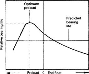
        bearing preload chartjpg.jpg

        .

        Hopper

        Thanks for posting that interesting ‘conceptual diagram’ … but, in the complete absence of X & Y axis scaling, it is only one [uncalibrated] step up from the ‘arm-waving’ explanations that we get from AstroPhysicists.

        Do you know of a version with at least some more numbers on it ?

        … or even just an indication of whether the sales are linear or logarithmic dont know

        MichaelG.

        #470922
        Ketan Swali
        Participant
          @ketanswali79440

          Hi Michael,

          Perhaps This link page 6 may help.

          Ketan at ARC.

          #470935
          Ketan Swali
          Participant
            @ketanswali79440

            Michael,

            Although I have given you the above link, I do think it is quite right for the subject being discussed.

            Ketan at ARC.

            #470938
            Howard Lewis
            Participant
              @howardlewis46836

              In automotive applications, preloading leads to premature failure, but in a machine tool application, some preloadi is needed to maintain accurate location. BUT, as the graph shows, excessive preload WILL shorten bearing life, so use the minimum advised by the bearing manufacturer.

              The preload for a particular bearing, or set of bearings, may well be expressed in terms of linear measurement.

              Even if not stated to be 0.00X" for a particular machine, it may be expressed in terms of a number of degrees of rotation of the adjusting nuts, such as "Zero end float, then tighten by 30 degrees", based upon the pitch of the adjusting thread.

              So don't overdo the good work, unless your hobby is changing bearings!

              Howard

              #470973
              Michael Gilligan
              Participant
                @michaelgilligan61133
                Posted by Ketan Swali on 11/05/2020 16:22:50:

                Hi Michael,

                Perhaps This link page 6 may help.

                Ketan at ARC.

                .

                Many thanks, Ketan

                ‘though not quite on this topic, it has numbers, etc  … which is a great advantage

                MichaelG.

                Edited By Michael Gilligan on 11/05/2020 19:00:58

                #492496
                Carl Wilson 4
                Participant
                  @carlwilson4

                  Just for information, you can check the bearing preload quite easily.

                  On the M250 when out of gear it should take 0.9 to 1.1Nm to turn the spindle if the preload is correct.

                  This can be checked by wrapping a piece of string around the periphery of your chuck and pulling with a spring balance. The load to get the spindle turning gives the torque.

                  By way of example:-

                  Torque is force x distance, the distance in this case being the chuck radius. For a 160mm dia chuck, the radius is 80mm or 0.08m.

                  The force required to give 0.9Nm at this radius will be 0.9/0.08=11.25N. Dividing by 9.81 to get Kg gives us 1.15Kg. Similarly for 1.1Nm we get 1.4kg. So if your spring balance value is between these figures then all is well.

                  #492517
                  not done it yet
                  Participant
                    @notdoneityet

                    Better than a spring balance is to hang on weights. 1.1kg mass – no go and 1.4kg gets it rolling. Better as long as their is sufficient space, of course.

                  Viewing 8 posts - 26 through 33 (of 33 total)
                  • Please log in to reply to this topic. Registering is free and easy using the links on the menu at the top of this page.

                  Advert

                  Latest Replies

                  Home Forums Manual machine tools Topics

                  Viewing 25 topics - 1 through 25 (of 25 total)
                  Viewing 25 topics - 1 through 25 (of 25 total)

                  View full reply list.

                  Advert

                  Newsletter Sign-up