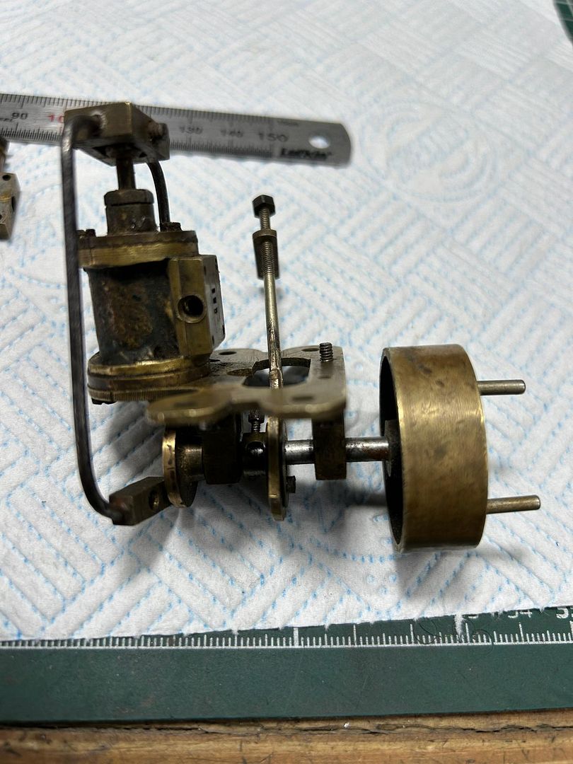
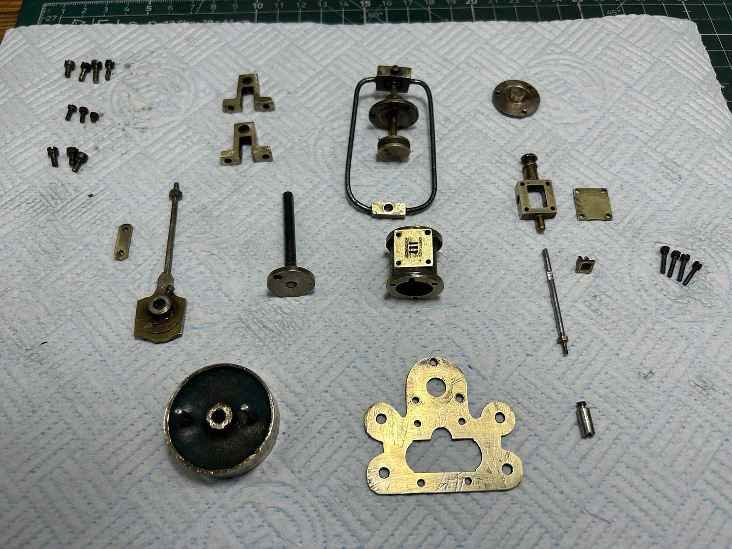
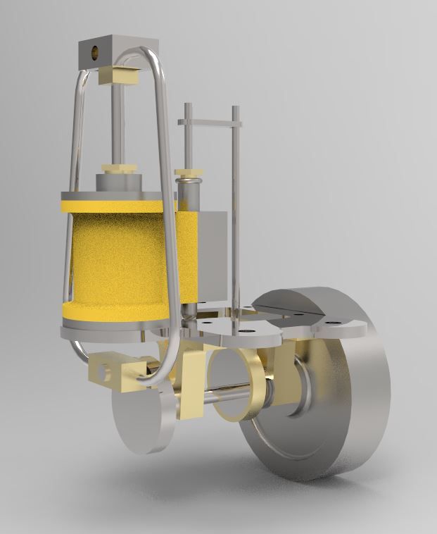
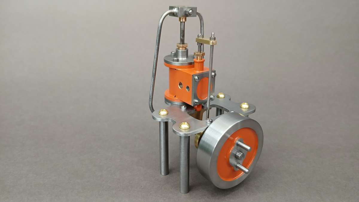
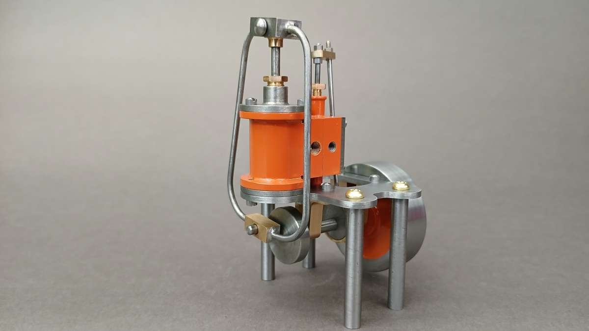
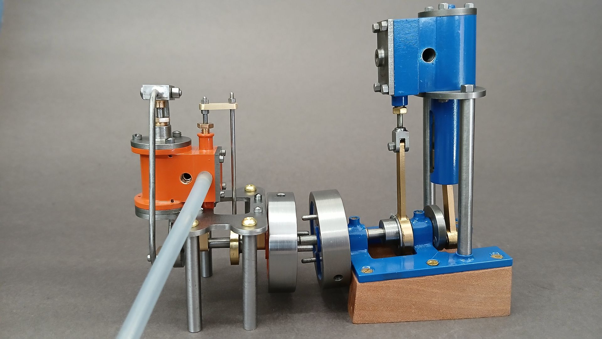
Sanjay’s Banjo Engine
Sanjay’s Banjo Engine
- This topic has 11 replies, 3 voices, and was last updated 13 July 2025 at 06:50 by
 Diogenes.


- Please log in to reply to this topic. Registering is free and easy using the links on the menu at the top of this page.
Latest Replies
-
- Topic
- Voices
- Last Post
-
-
Alternatives for a DRO display change
Started by:
John Hinkley
in: General Questions
- 8
-
1 September 2025 at 23:20
mark costello 1
-
Softening epoxy
1
2
Started by:
John Haine
in: General Questions
- 22
-
1 September 2025 at 22:59
Dick H
-
Looking for a quality pencil sharpener
Started by:
Greensands
in: The Tea Room
- 10
-
1 September 2025 at 20:51
Greensands
-
Swing over bed limitation for flywheels
Started by:
Steve Huckins
in: General Questions
- 7
-
1 September 2025 at 20:50
Bazyle
-
Thread form of medical ‘screws’.
Started by:
JimmieS
in: The Tea Room
- 7
-
1 September 2025 at 20:45
JimmieS
-
Task Light
Started by:
Vic
in: Work In Progress and completed items
- 1
-
1 September 2025 at 20:03
Vic
-
Knowledge
Started by:
seanieboy
in: Introduce Yourself – New members start here!
- 5
-
1 September 2025 at 19:39
Roderick Jenkins
-
Newbie
Started by:
seanieboy
in: Introduce Yourself – New members start here!
- 2
-
1 September 2025 at 19:16
bernard towers
-
New Member
Started by:
daves 1
in: Introduce Yourself – New members start here!
- 4
-
1 September 2025 at 19:15
bernard towers
-
Big Vise, go big or go home
Started by:
conrod
in: Workshop Tools and Tooling
- 4
-
1 September 2025 at 18:38
not done it yet
-
What Did You Do Today 2025
1
2
…
9
10
Started by:
JasonB
in: The Tea Room
- 38
-
1 September 2025 at 18:12
Wade Beatty
-
Parting off on a mini lathe
Started by:
Andy Brocklehurst
in: Beginners questions
- 18
-
1 September 2025 at 18:07
JasonB
-
Feed Water
1
2
Started by:
Richard Simpson
in: General Questions
- 16
-
1 September 2025 at 16:21
larry phelan 1
-
Hello.
Started by:
smokeyjoe25
in: Introduce Yourself – New members start here!
- 4
-
1 September 2025 at 11:57
noel shelley
-
Emco Compact 5 Modifications
1
2
…
4
5
Started by:
Graham Meek
in: Manual machine tools
- 12
-
1 September 2025 at 09:57
Graham Meek
-
Myford VMB mill, head lift.
Started by:
lctikka61
in: Manual machine tools
- 5
-
31 August 2025 at 22:45
lctikka61
-
End Mill Sharpening Jig
Started by:
Vic
in: Workshop Tools and Tooling
- 10
-
31 August 2025 at 22:38
Vic
-
The Latest INDEX to Model Engineer & Workshop (Also past issues of MEW)
1
2
Started by:
David Frith
in: Model Engineer & Workshop
- 7
-
31 August 2025 at 20:23
David Frith
-
Folding Knife
Started by:
Vic
in: The Tea Room
- 5
-
31 August 2025 at 16:47
Robert Atkinson 2
-
Sensitive tailstock for mini lathe
Started by:
dk0
in: Workshop Tools and Tooling
- 10
-
31 August 2025 at 15:42
old mart
-
Dickson Tooling Offer
Started by:
JohnF
in: Hints And Tips for model engineers
- 12
-
31 August 2025 at 10:57
southernchap
-
Milling for beginners book, Where?
Started by:
andy198712
in: Beginners questions
- 9
-
31 August 2025 at 10:34
southernchap
-
NU tool milling machine
Started by:
joseph tatler
in: Manual machine tools
- 8
-
31 August 2025 at 10:15
southernchap
-
My week this week! My workshop videos
1
2
…
11
12
Started by:
Phil Whitley
in: The Tea Room
- 16
-
30 August 2025 at 18:55
Phil Whitley
-
Mesh Communication
Started by:
Vic
in: The Tea Room
- 4
-
30 August 2025 at 18:17
Vic
-
Alternatives for a DRO display change


