Running M type motor underneath and what do I actually have?.

Advert

Running M type motor underneath and what do I actually have?.

Home Forums General Questions Running M type motor underneath and what do I actually have?.

Viewing 8 posts - 1 through 8 (of 8 total)
  • Author
    Posts
  • #406060
    Grant Allen 1
    Participant
      @grantallen1

      Good afternoon forum. I looking for images, ideas or descriptions of how I can run the pulley gear and motor under the lathe to save room. I reckon that I'm looking at either constructing some extra pulleys to take it underneath or splitting the large pulley and keeping that on top and the motor below. What do you all think is best way to go.

      I am currently refurbishing a M type 3 1/2" long bed lathe, I'm unsure which it is either drummond or myford as the gear guard has a cast myford on it but doesnt have the typical myford on the base. The gear plate is on the guard not the base. If any one can clear up what it actually is brilliant, oh and its stamped at the end of the bed (J3567).

      Advert
      #26570
      Grant Allen 1
      Participant
        @grantallen1
        #406066
        Clive Foster
        Participant
          @clivefoster55965

          Grant

          If you are planning to put your M type on a conventional flat top bench with its back against the wall rather than using legs of some description, whether standard castings or something functionally equivalent, the running the drive underneath is hardly worth the effort.

          Especially if you use poly-Vee belts and pulleys.

          The secret to a compact, above the bench, drive is to use a two stage primary drive so you don't need to accommodate unreasonably large pulleys. Use an L shape layout tucking the motor mostly underneath the back gear outrigger assembly with the first stage of the primary drive running away from the lathe towards the back of the bench. Second stage runs upwards to the countershaft proper at the same height as the lathe centreline so the final drive runs straight forward from countershaft to mandrel.

          I have used variations of this layout on a couple of South-Bend 9" lathes to fit them onto an 18" wide bench. Admittedly with some cross slide overhang but the saddle hand wheels were within the width of the bench. Just! Back then I had to use A section Vee belts for the primary drives so smallest practical final drive pulleys could use were, from memory, about 8" diameter. Very small Vee pulleys are a waste of time due to power transmission issues. My small ones were probably around 3" or 3 1/2" diameter. About as small as makes sense for a good drive in A section. Countershaft speed probably around 250-300 rpm on the first effort. Later modified with a two speed and tight – slack belt clutch assembly. Some creativity was need to squeeze it all in but worth the effort.

          If you use poly-Vee belts you can probably get down to 4" or so diameter pulleys so it all becomes smaller. Poly-Vee works better than flat belt on the final drive too.

          I initially just hinged the motor off the bench for first stage belt tensioning with the second stage bearing assembly floating freely and a normal pivot arm mount for tensioning the final drive. For the second version I fixed the motor and arranged the second shaft to move under lever and spring control to act as a clutch. Robbed the nice cast alloy tube and shaft bearing assembly from a defunct spin drier to make the second shaft unit. My primary drive was pretty much in line with the chuck so a swarf shield was essential. Putting it the other way round got in the way of the drop gear banjo. Second stage was on the usual side.

          Of course there is no reason why you couldn't do something similar with the motor under the bench with the second stage drive poking up through. Its little bit easier as there is more room but it doesn't really win much space as accommodating the final drive run and the drive pulley on the countershaft really defines the amount of room needed. Realistically 4" or 5" is the smallest drive pulley you can use so there will be space for the motor up on top.

          Realistically a bench 18" wide from the wall is about as narrow as can accommodate this class of machine.

          Clive

          #406086
          Niels Abildgaard
          Participant
            @nielsabildgaard33719

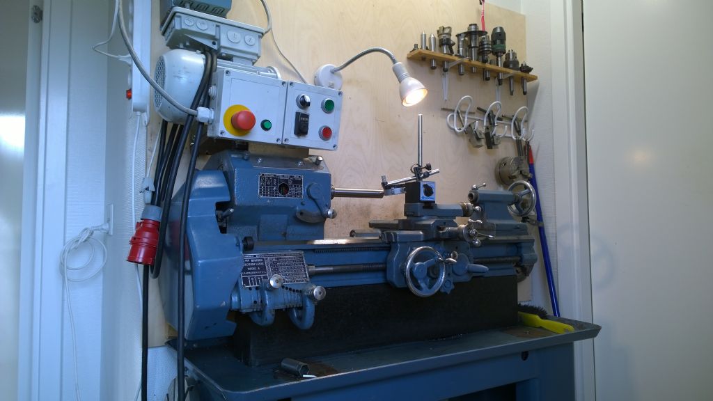
            If space is a consideration ,putting motor on top is working quite well.

            Boxford VFD

            RockFord

            Edited By Niels Abildgaard on 22/04/2019 21:17:11

            #406090
            Clive Foster
            Participant
              @clivefoster55965

              Niels picture reminds me that I did a very simple semi overhead set up to put my Pools `Special lathe on that same 18" wide bench. I welded up a very simple rectangular angle iron frame arranged to pivot off the bench immediately behind the foot and central relative to the headstock pulleys. (This was the first application for my stiff, "car heater hose in a tube", vibration reducing pivots which worked very well proving the idea worth making note of.)

              The countershaft ran in simple ball bearing plummer blocks as close tot eh top of the fame as could be managed whilst still providing pulley and belt clearance. The motor hung off the frame on simple pivoted, sheet brackets (more heater hose in tubes) on the bottom side of middle. Position chosen so the weight of the motor helped tension the primary drive belt and pulley that I happened to have about the place. The frame was leant back as far as possible given the need for clearance between belt and backgear. With a simple final drive belt guard fabricated from hardboard the whole thing had a vaguely Myford 7 ish air.

              Clive

              #406098
              Howard Lewis
              Participant
                @howardlewis46836

                According to Tony Griffiths of Lathes UK.

                If it is Ml1 or 2 Centre Height will be 3.125" ML3 and 4 are 3.5" centre height. The odd nos are 15" centres, the even are 20". On most MLs the gear cover hinges upwards on a shaft nigh up behind the Headstock. Apparently, a great rarity is a side hinged gear cover. The Banjo is straight. The Saddle Handwheel turned clockwise, will move the Saddle towards the Headstock. The Cross and Top Slide threads are 12 tpi and the 80 divisions on the dials give an increment that is not a thou!

                Only very early MLs have the Headstock cast as one with the Bed. Later ones, the majority as I understand it have bolt on Headstocks.

                To use the 8 tpi Leadscrew to power the Saddle towards the Headstock requires two stages of reduction in the Changewheels (Two studs carying Idler or Compound gears ).

                HTH

                Howard

                Edited By Howard Lewis on 22/04/2019 22:27:14

                #406116
                Hopper
                Participant
                  @hopper

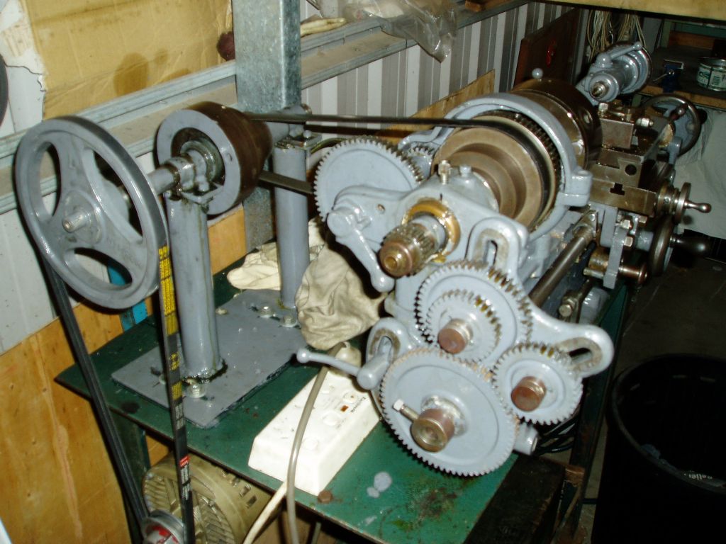
                  Here's a pic of how I fitted the motor underslung below the bench on my M-type. I did it to get the motor right away from the swarf zone as it is the type that air is blown right into the windings and armature of the motor and hand become packed solid with swarf over the years.

                  It's easy enough to do, I just hung a flat plate on the undeside side of the bench and bolted the motor to the plate. Plate was pivoted at the front edge on a couple of angle-iron brackets to a pair of angle iron brackets bolted to the lathe bench. A length of threaded rod was attached to the rear of the plate and comes up through a hole drilled in the bench and tension is adjusted with nut, lock nut and flat washer. Motor weight holds the tension on the belt, as far as the nut lets the plate move.

                  p1010097.jpg

                  The serial number you quote does not sound like M-type with the letter J in it. Not sure there. Lathes.co.uk has full listing of M-type numbers by year in the Drummond section, so you could check that and check their Myford section to see if it matches ML1-4 etc. And post some pics of your lathe here and someone can  probably tell you what you have.

                  Some giveaways of a later Drummond M-type would be the use of V belts on the countershaft and headstock pulleys and the use of steel handles on the carriage traverse and leadscrew handwheels instead of the earlier black animal horn. I don't know that the M-type ever had Myford cast into the bed?

                  Edited By Hopper on 23/04/2019 05:48:15

                  #406122
                  Nicholas Farr
                  Participant
                    @nicholasfarr14254

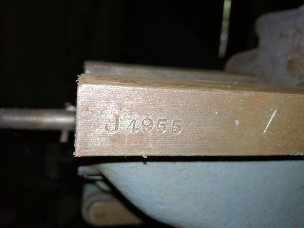
                    Hi, the letter J is mentioned for the Myford/Drummond M type in this **LINK**.

                    Just had a look at mine and it has a J prefix, but it looks like it may have been added later, maybe this is one of those that were handed over to Myford from Drummond's.

                    img_20190423_074041.jpg

                    Regards Nick.

                    Edited By Nicholas Farr on 23/04/2019 08:03:47

                  Viewing 8 posts - 1 through 8 (of 8 total)
                  • Please log in to reply to this topic. Registering is free and easy using the links on the menu at the top of this page.

                  Advert

                  Latest Replies

                  Home Forums General Questions Topics

                  Viewing 25 topics - 1 through 25 (of 25 total)
                  Viewing 25 topics - 1 through 25 (of 25 total)

                  View full reply list.

                  Advert

                  Newsletter Sign-up