Perfecto 3-1/2″ x 16″ lathe half nut lever operation

Advert

Perfecto 3-1/2″ x 16″ lathe half nut lever operation

Home Forums Manual machine tools Perfecto 3-1/2″ x 16″ lathe half nut lever operation

Viewing 15 posts - 1 through 15 (of 15 total)
  • Author
    Posts
  • #431079
    Charles R
    Participant
      @charlesr45326

      Hi,

      Wondering if anyone on here has the same model lathe as me, which is a Perfecto 3-1/2" x 16" BG SC centre lathe?

      I acquired mine recently and am going through everything to try and get it in tip top shape as it hadn't been used for some time before I purchased it and inevitably, because of it's age, has some wear in various places.

      If someone on here owns this model, I'd like to know what's involved in operating the half nuts?

      The Perfecto lathes are very similar to the Myford ML2 and ML4 machines but differ in the way the power feed lever engages the half nuts.

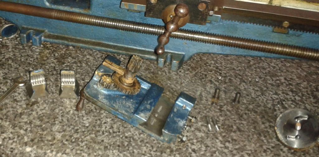
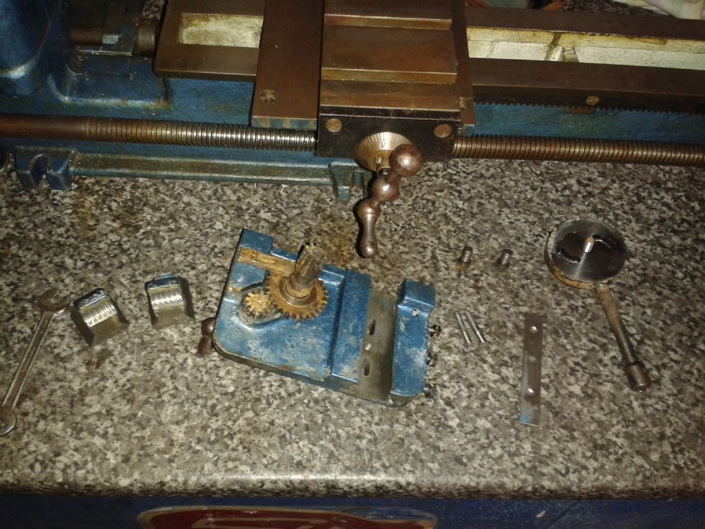
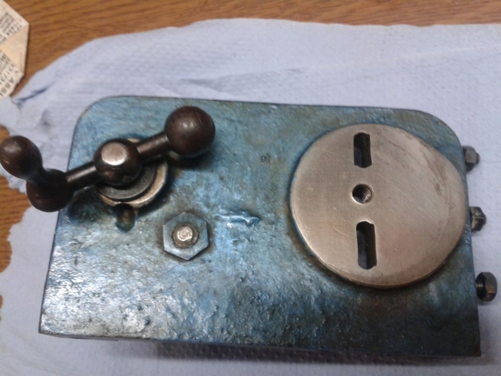
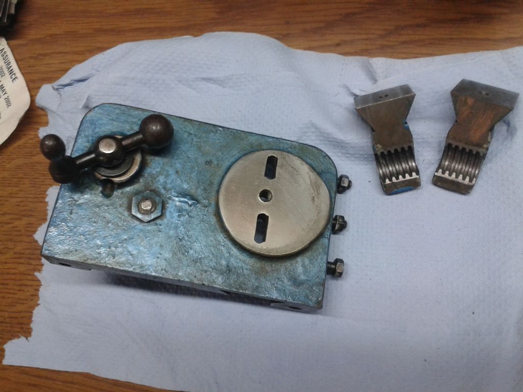
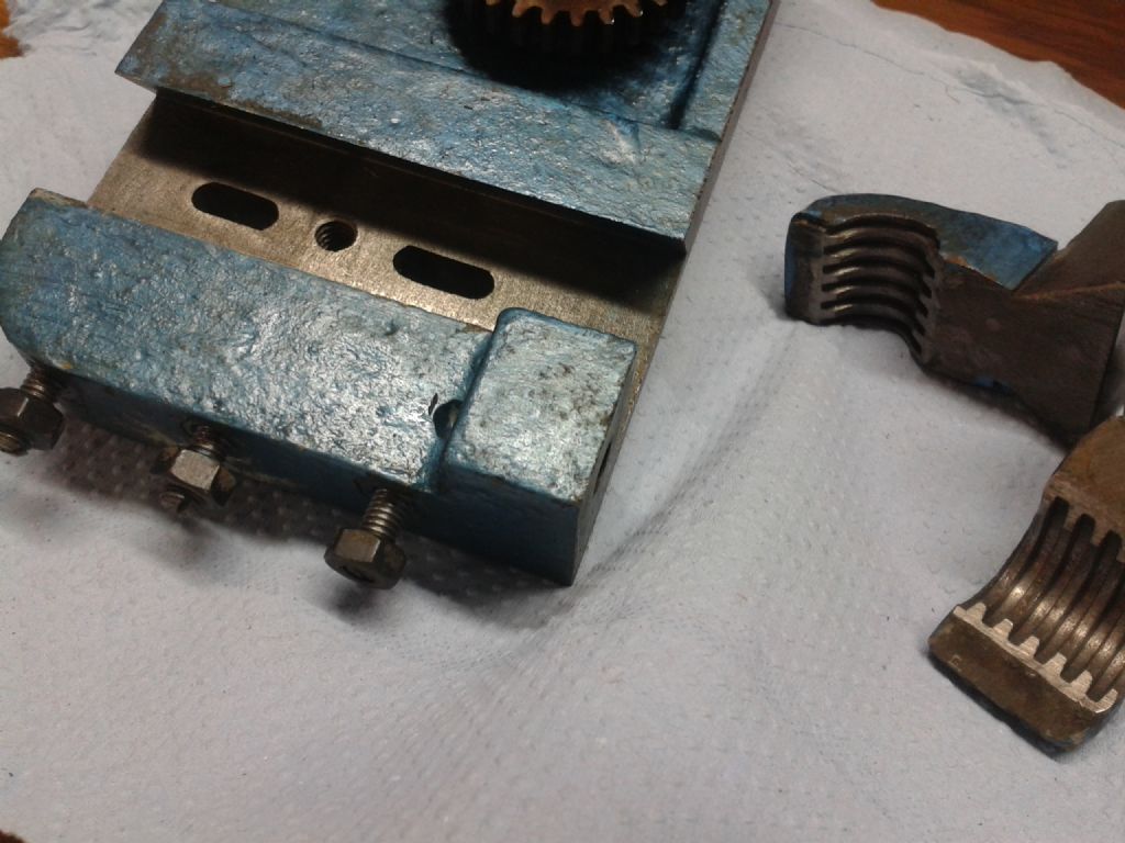
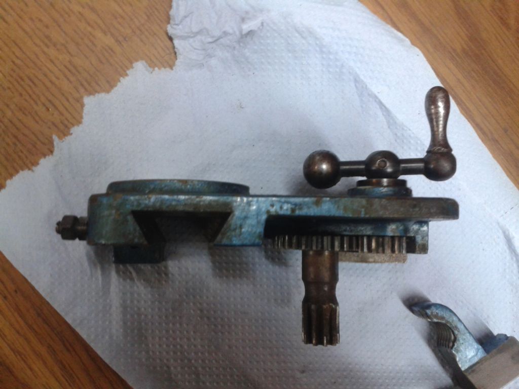
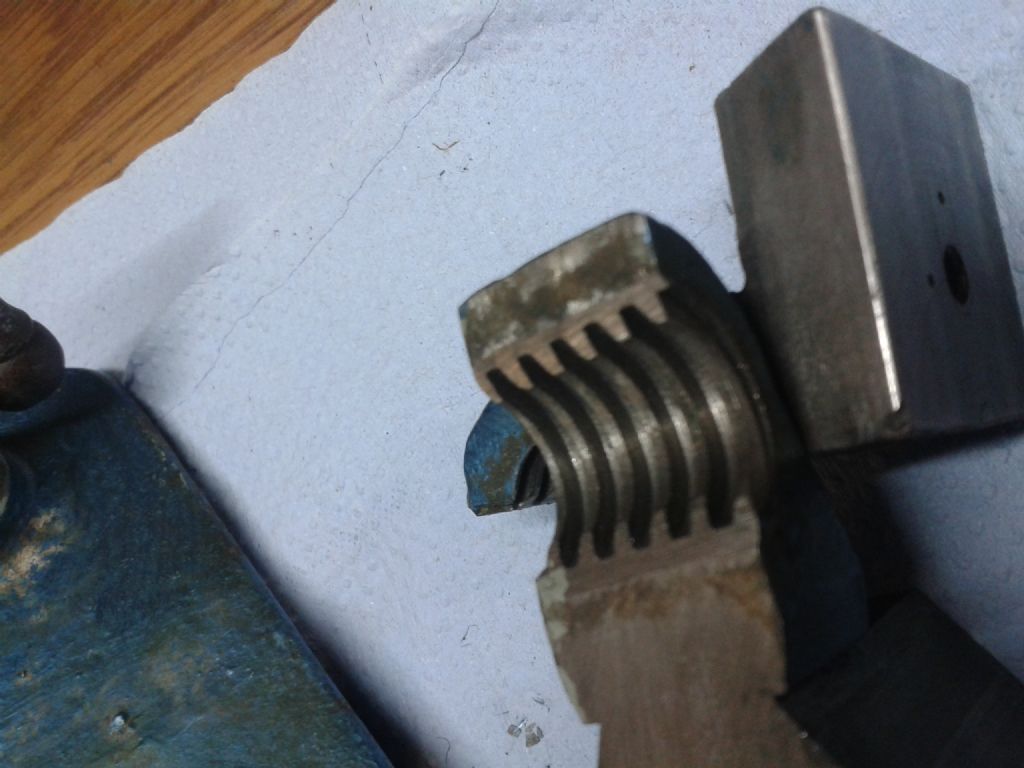
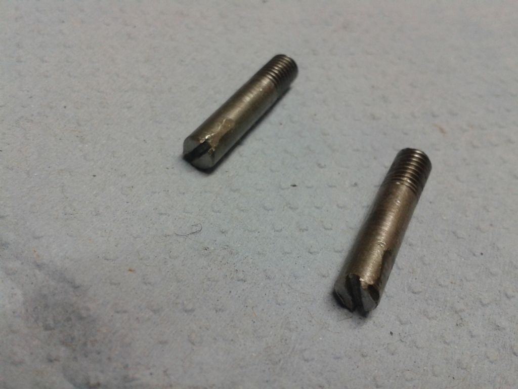
      As my lever is a bit loose when disengaged and stiff to engage when wishing to use the power feed, I dismantled the apron to see what was amiss and the main issue appears to be the fact that I discovered the studs which screw into each half nut are slightly bent, so inhibiting smooth movement when trying to operate the lever. To remedy this, I intend to try and machine some new studs.

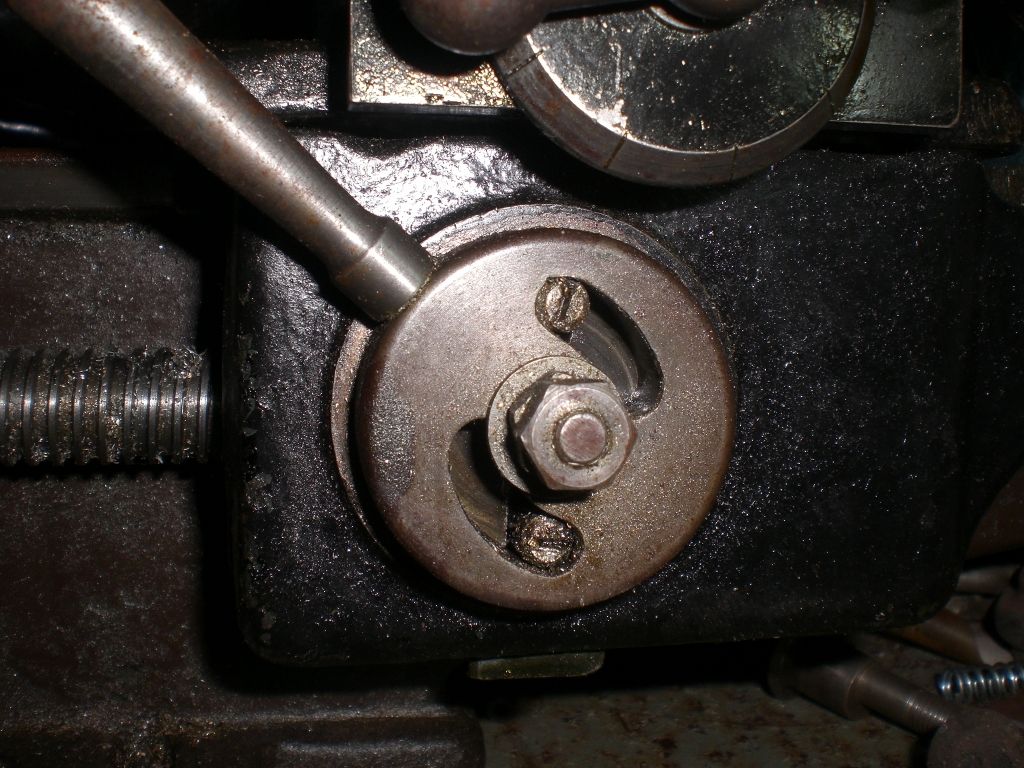
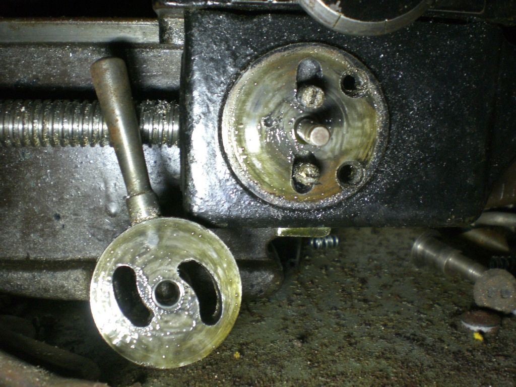
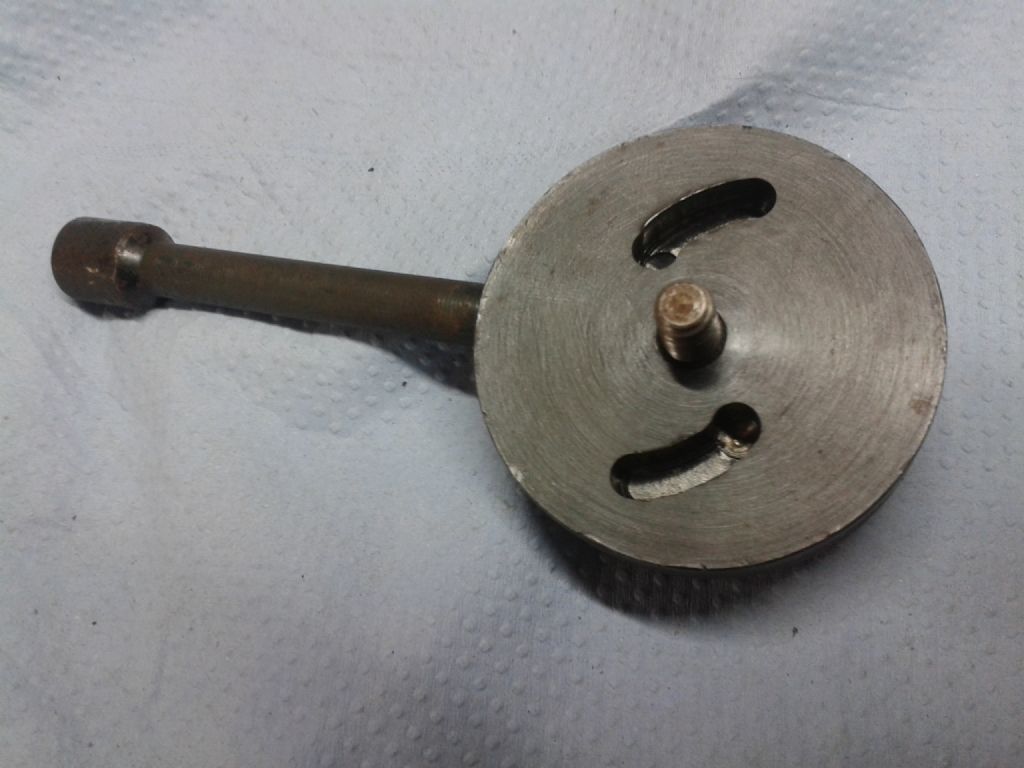
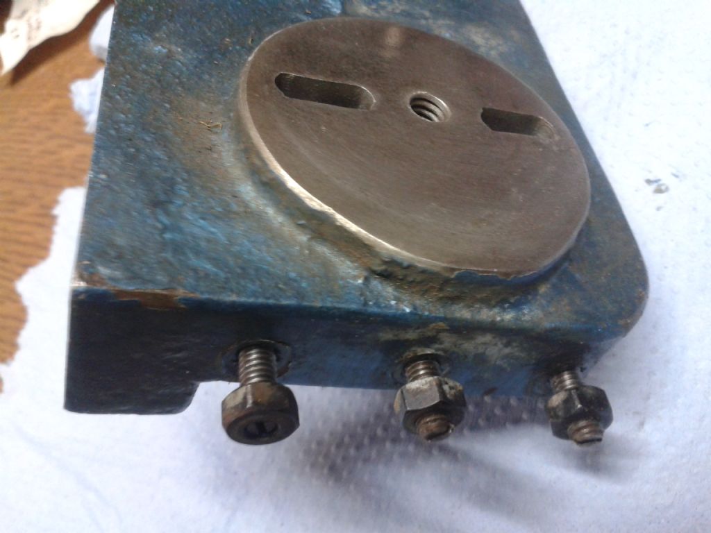
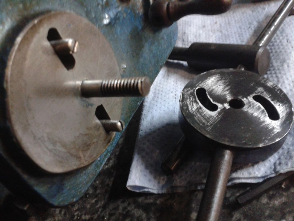
      However, I'm wondering if something is missing on my setup as on the back of the engagement lever are two machined curved slots into which the half nut studs locate and slide through these curved slots to engage and disengage the power feed. In the base of the curved slots appear to be detents but I can't see how this will keep the half nuts disengaged (and the operating lever from suddenly dropping into engage mode) without the use of a ball/spring somewhere unless the whole arrangement merely relies on friction to hold?

      If anyone has knowledge of the inner workings of this mechanism, please enlighten me as to how this design is supposed to work.

      Thanks for reading.

      Advert
      #13653
      Charles R
      Participant
        @charlesr45326
        #431108
        Charles R
        Participant
          @charlesr45326

          Here's a photo showing the parts…sorry about the image quality!

          half nuts.jpg

          #431109
          Charles R
          Participant
            @charlesr45326

            …and another.

            half nuts 2.jpg

            #431123
            Nigel Graham 2
            Participant
              @nigelgraham2

              I don't know the particular lathes, I'm afraid but can offer this:

              The half-nut control is very unlikely to have relied on friction to hold its selected position.

              If the half-nut control relied on a sprung detent that has absconded, there ought be traces such as hemi-spherical drillings, probably somewhere on the apron, to accept the sprung ball or plunger.

              I have just a quick shufti in the Fount of Knowledge – Tony Griffiths' 'Lathes.co' web-site – and unless another contributor can answer directly, I suggest seeing if the Perfecto "chapter" therein gives any useful details. Its photos of restored Perfecto lathes clearly show the clasp-nut lever sprouting from a large disc, and I suspect as you do, that this disc holds a detent working in aforementioned drillings. Or would, if not missing from the lathe receiving attention.

              Examine the part of the outer face of the apron normally covered by the disc, and see if it has any features that match ones on the inner face of the disc. The missing bits might be as simple as a short coil-spring and a ball or short pin, housed in a blind hole in either the disc or apron, and mating with said hollows in the other.

              I did not search further, but Mr. Griffiths may have facsimiles of the Perfecto lathe manual for sale. I have bought corresponding ones for my machine-tools, from him.

              #431133
              Diogenes
              Participant
                @diogenes

                I have just been out to check my memory of the ML4 apron in my slippers, and the omens are all good; the action is virtually identical – the handle is held in the up (disengaged) position by friction alone, derived from judicious adjustment of the gib.

                Whilst I can't guarantee that mine hasn't been mutilated in some subtle way over the years, there are no detents of any kind, or evidence of there ever having been so, and it used to operate quite satisfactorily. The gibs are not over tight – the operation is light, but there is enough friction to hold the lever in the "up" position – perhaps because the dovetail contact area is quite generously proportioned, as I see is yours.

                I'd use grease (rather than oil) as a lubricant during re-assembly, and carry out a final adjustment once it's all back together and hanging in it's proper place on the saddle.

                If you'll pardon the question, what are your half-nuts made of? ..perhaps it's a trick of the light, but I'd hope it was some kind of bronze..

                Good luck with the restoration.

                #431134
                Diogenes
                Participant
                  @diogenes

                  Just to reassure; because the half-nuts are balanced, i.e. the upper one is held up by the lower, if you will, the only out of balance part that gravity would have to overcome would be the weight of the small operating handle – friction in the gib alone is sufficient to overcome this, whilst still providing light operation..

                  #431140
                  Nicholas Farr
                  Participant
                    @nicholasfarr14254

                    Hi Charles, just had a look at a lathe that I have that has a similar arrangement. This one has the slots cut right through the lever disc. Taking it off shows no detents at all and it just relies on enough friction, via the two nuts holding the lever in place, to stop it flopping down, however with it loose, there is no suggestion that it would engage under gravity alone anyway.

                    feed engagement 1.jpg

                    feed engagement 2.jpg

                    As Diogenes has said, that if your if your gib is adjusted correctly, that should be enough to hold them in the position that you select. That fact that yours appear to have two indents may be somewhat misleading and these may just be drillings to start the end mill for cutting the slots during the manufacturing process. I think you'd be hard pushed to get any sort of useful indent in them.

                    Regards Nick.

                    Edited By Nicholas Farr on 30/09/2019 08:53:50

                    #431141
                    Brian Wood
                    Participant
                      @brianwood45127

                      I can confirm that the ML4 lathe had a very similar mechanism and relied on the friction grip from a split washer below the doubled clamping nuts in the middle of the operating lever to keep it engaged and disengaged as appropriate.

                      The degree of friction could be chosen from these two nuts with the second acting as a locknut to hold the setting

                      Regards Brian

                      #431155
                      Raymond Griffin
                      Participant
                        @raymondgriffin40985

                        Hi, I have the one of these lathes. It sounds as though somebody has been very heavy handed on the lever: to bend the pins. I also have a copy of the instructions and a screw cutting chart and can send them on to an e-mail address. Ray

                        #431157
                        ega
                        Participant
                          @ega

                          A detent would seem to imply a fixed position of the engaged halfnuts ie no adjustment. Later Myfords have a limit screw to prevent overtight adjustment.

                          #431278
                          Charles R
                          Participant
                            @charlesr45326

                            I'm overwhelmed with everyone's willingness to be helpful and to take time to post replies…it's very much appreciated.

                            I had a more in depth look today and it very much seems like my setup is indeed working on friction alone like most people have suggested.

                            The half nut pins are pretty useless now bent, so I intend to make some replacement ones.

                            Some more photos below…

                            3.jpg

                            4.jpg

                            5.jpg

                            6.jpg

                            7.jpg

                            8.jpg

                            9.jpg

                            10.jpg

                            11.jpg

                            #431524
                            Charles R
                            Participant
                              @charlesr45326
                              Posted by Raymond Griffin on 30/09/2019 10:52:03:

                              Hi, I have the one of these lathes. It sounds as though somebody has been very heavy handed on the lever: to bend the pins. I also have a copy of the instructions and a screw cutting chart and can send them on to an e-mail address. Ray

                              Hi Ray…yes please for the copies!

                              I sent you my details via pm just after you posted this.

                              Regards, Charles

                              #431563
                              Diogenes
                              Participant
                                @diogenes

                                Hi Charles, looking good.

                                Whilst it is apart, it might be worth checking for burrs along the edges of the pin slots, particularly the curved ones in the disc. As well as any obvious ones caused by damage, also check with a finger for any feeling of sharpness inside the track edges (overtightening of the disc in the past can sometimes cause burrs here).

                                In the ML (albeit the tracks are a slightly different shape), burrs along the lip of the track can give a rough action or even cause sticking, and it could be this which has caused someone to be rather rough with yours.

                                If any are present, lightly dressing them back with a small file gives a noticeably smoother action.

                                Happy to see it progressing,

                                D

                                #431603
                                Charles R
                                Participant
                                  @charlesr45326

                                  Hi Diogenes, thanks.

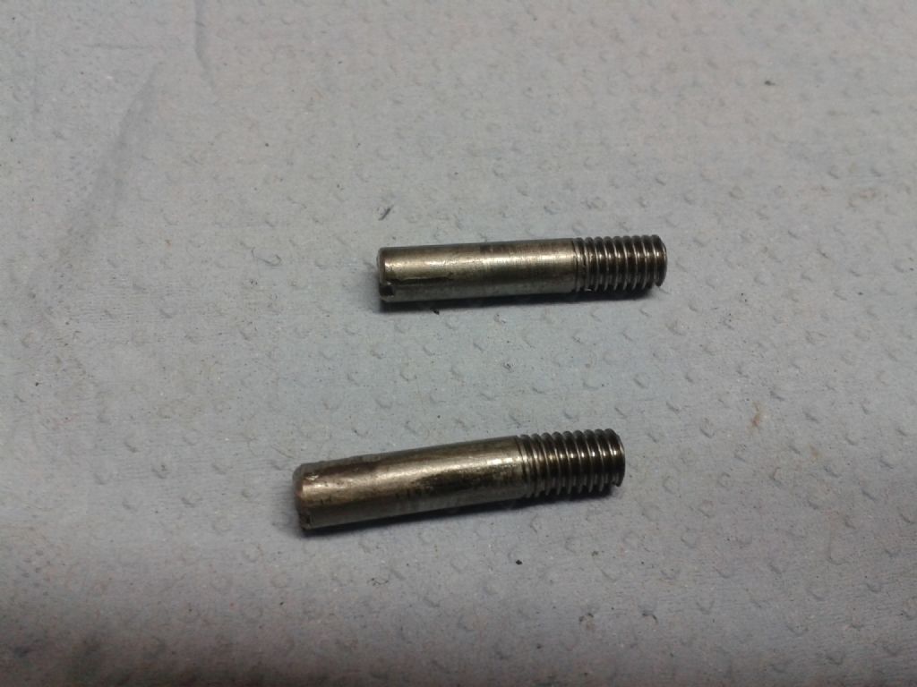
                                  I made some new pins and deburred the curved slots yesterday as they were indeed pretty rough!

                                  The whole mechanism is working much better now.

                                  20191002_174845.jpg

                                Viewing 15 posts - 1 through 15 (of 15 total)
                                • Please log in to reply to this topic. Registering is free and easy using the links on the menu at the top of this page.

                                Advert

                                Latest Replies

                                Home Forums Manual machine tools Topics

                                Viewing 25 topics - 1 through 25 (of 25 total)
                                Viewing 25 topics - 1 through 25 (of 25 total)

                                View full reply list.

                                Advert

                                Newsletter Sign-up