Motor connection

Advert

Motor connection

Viewing 25 posts - 1 through 25 (of 50 total)
  • Author
    Posts
  • #291422
    gerry madden
    Participant
      @gerrymadden53711

      I have just go a fractional HP motor 250V single phase. In its top mounted box it has a start and run capacitor. I assumed this could be connected directly to the mains supply but in browsing a Clark catalogue it suggest they motors should be connected via a DOL. Can anyone advise me here as to the purpose of DOL and why I might or might not need one ?

      Advert
      #32941
      gerry madden
      Participant
        @gerrymadden53711
        #291426
        john fletcher 1
        Participant
          @johnfletcher1

          Clark are right. The idea of a DOL is as follows,should you be working on say your lathe and the there is a power OUT for whatever reason, and you could just be making some adjustment to the chuck and then the power is then restored you could be seriously injured. The DOL would protect you, as you would need to press the GREEN on button to restore the power. Also within the "box" there are overloads as well.John

          #291434
          Emgee
          Participant
            @emgee

            For those who may be wondering, the DOL mentioned is a Direct Online Starter, this will as John states disconnect the motor connection when power is lost and also provide motor overload protection so it is important to set the overload device to the same as the full load current amps (FLC) stated on the motor plate.

            Emgee

            #291436
            gerry madden
            Participant
              @gerrymadden53711

              Thank you all for that clear guidance which I will follow. What a great forum this is !

              #291446
              Speedy Builder5
              Participant
                @speedybuilder5

                I have a Boxford lathe. My emergency STOP switch breaks on power out. Next is the on/off switch that breaks if any of the cupboard doors are opened (Screw cut gears, motor speed, backgear select etc), then I have a rotary switch for forward, off and reverse.
                BobH

                #291468
                Neil Wyatt
                Moderator
                  @neilwyatt

                  If you search for NVR ('no voltage release&#39 switch you might find something cheaper that does the same job.
                  Several of our advertisers sell a little unit combining a start and stop switch with an NVR and a hinged red emergency STOP button as fitted to many types of machine.

                  Neil

                  #291472
                  MW
                  Participant
                    @mw27036

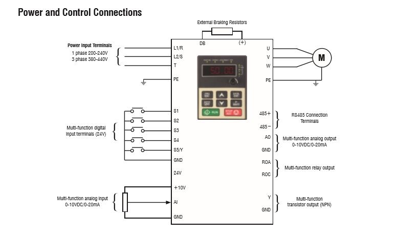
                    I don't want to hijack the original poster but is there a way to combine an emergency stop to a lathe controlled by an inverter/electronic pendant? I'm just saying because I don't have one and ideally I should.

                    The stop button is a little obscure for when my hand might be trappedindecision

                    Michael W

                    #291485
                    Keith Long
                    Participant
                      @keithlong89920

                      Gerry – a word of caution, the DOL that Clarke sell is NOT an NVR switch. It is mechanically locked on so that if the mains fails the contacts actually stay in the made position with the result that the motor WILL restart when the mains comes back on ie it's no different in function to an ordinary on/off switch apart from having the over-current device built in. If you want a starter that gives you the NVR protection, look in the Toolstation or Screwfix catalogues. Machine Mart's reason for stating that the motor must be connected through a DOL starter is to have it connected to the mains through an over current protection device, to save the motor being run at overload an burning out. Both Toolstation and Screwfix sell the over-current protection devices separately and you choose the one that suits your motor.

                      #291495
                      Les Jones 1
                      Participant
                        @lesjones1

                        Mitchael-w,
                        You can probably connect an emergency stop button in series with the stop button on the pendant. This is assuming that the stop button in the pendant is an normally closed contact type. To be sure you would need to provide w wiring diagram of the pendant and how it is wired to the inverter. Also a copy of the page of the inverter manu manual that shows the control input connections. would be helpful.

                        Les.

                        #291496
                        MW
                        Participant
                          @mw27036
                          Posted by Les Jones 1 on 31/03/2017 17:54:43:

                          Mitchael-w,
                          You can probably connect an emergency stop button in series with the stop button on the pendant. This is assuming that the stop button in the pendant is an normally closed contact type. To be sure you would need to provide w wiring diagram of the pendant and how it is wired to the inverter. Also a copy of the page of the inverter manu manual that shows the control input connections. would be helpful.

                          Les.

                          Thanks Les, it'll take a little time but i'll go and see what it looks like.

                          Michael W

                          #291501
                          Neil Wyatt
                          Moderator
                            @neilwyatt
                            #291504
                            MW
                            Participant
                              @mw27036

                              Ah whoa, thank you!

                              I have a pendant, inverter and motor that's very similar to yours,

                              I bought a TEC motor which was 1/2HP, I did okay with it for a long time til i needed to turn a long length of EN3 BMS square bar for a T bolt (to fix a toolpost to) and ran table down the bed of my Clarke using the gear train, however, it stalled half way through the cut, as it wasn't able to handle both the spindle and the gear train at the same time (thankfully, it stopped, so it didn't kill the motor and i was able to re-use it on my mill when the original DC motor packed up).

                              So i upgraded to a 1HP motor, not wanting to go overkill but at the same time, solve the problem. I've operated this one ever since and it's been able to handle anything I've thrown at it.

                              I was going to say that i would've assumed that one needed to place the emergency in series with the single phase lead to the inverter, as this would be the source of power, breaking that part of the circuit cuts everything else instantly. I didn't think that it would be able to run this function through the inverter electronically?

                              Although i suppose breaking any part of the circuit to the control would create an incomplete path causing it to stop?

                              Michael W


                              Edited By Michael-w on 31/03/2017 19:04:01

                              #291507
                              not done it yet
                              Participant
                                @notdoneityet

                                A good article on a real life fix (several times over). Off topic really, but my immediate thought was why he made a new counter shaft – I would have used the dead motor and added a pulley somehow.

                                #291508
                                MW
                                Participant
                                  @mw27036

                                  img.jpg

                                  That is what my inverter terminals look like, so it's a bit different to how they name the terminals on the jaguar.

                                  #291512
                                  Les Jones 1
                                  Participant
                                    @lesjones1

                                    Hi Mitchael-w,
                                    We now need to know the functions that are configured on the multi function inputs S1 to S4 and S5/Y. We also need the schematic of the pendant so we know which switches / buttons are connected to each of the control inputs.

                                    Les.

                                    #291513
                                    MW
                                    Participant
                                      @mw27036

                                      I've had a look through the manual of the IMO idrive 2 inverter, but i can't find any reference to a facility to emergency stop on it, i'm doubtful as to whether my particular model is able to do this unfortunately.

                                      Guess that's what you pay for on an jaguar.

                                      Michael W

                                      #291516
                                      MW
                                      Participant
                                        @mw27036

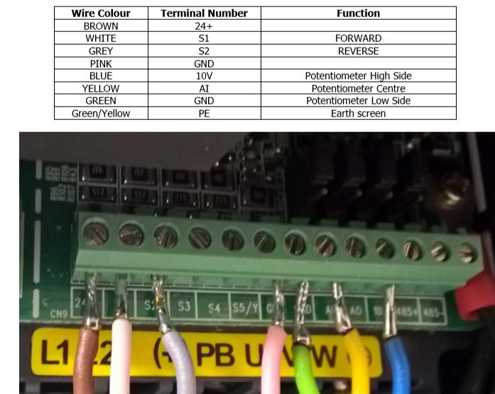
                                        Ok i'll see what i can do Les, however, i don't think i ever got a circuitry diagram nor can i find one online however, i can open the thing up and see if i can make sense of the spaghetti inside, this is the best thing i could find on "what does what" for the pendant in relation to the inverter.

                                        img2.jpg

                                        #291532
                                        John Rudd
                                        Participant
                                          @johnrudd16576

                                          I would never rely on the software of any piece of equipment when it comes to stopping it dead in an emergency….

                                          In an industrial environment, an E stop is exactly that….it is hard wired doesnt rely on software code…why would you want to compromise on safety?

                                          Remove the power……

                                          I have three lathes and two mills, all of their E stops kill the power….

                                          Is there a better solution?

                                          Edited By John Rudd on 31/03/2017 21:38:20

                                          #291533
                                          MW
                                          Participant
                                            @mw27036
                                            Posted by John Rudd on 31/03/2017 21:35:33:

                                            I would never rely on the software of any piece of equipment when it comes to stopping it dead in an emergency….

                                            In an industrial environment, an E stop is exactly that….it is hard wired doesnt rely on software code…why would you want to compromise on safety?

                                            Remove the power……

                                            Edited By John Rudd on 31/03/2017 21:36:34

                                            it isn't exactly software but more like an electronic input rather than a raw electrical one, I agree, my first instinct would be isolating the power supply, i'm going to upload some more pictures of my pendant, to weed out where all these wires are going to see if the electrical gurus can take a crack at it first. They might know something I don't!

                                            I just took so long because my computer seemed to have a miniature fit over transferring the photos (curse you, windows app; TWINUI) For now i'm going to have to review everything thru paint.

                                            Michael W

                                            #291537
                                            John Rudd
                                            Participant
                                              @johnrudd16576
                                              Posted by Michael-w on 31/03/2017 21:41:44:

                                              it isn't exactly software but more like an electronic input rather than a raw electrical one…..

                                              Michael W

                                              The control terminals of an inverter are the external interface that is controlled by software….thats my point…

                                              Remove the power, the inverter/motor is dead….

                                              #291541
                                              Les Jones 1
                                              Participant
                                                @lesjones1

                                                Hi Mitchael-w,
                                                Does the pendant have a three way switch (Forward, stop, reverse) or does it have three buttons (Forward, stop, reverse) ?

                                                John makes a good point about having the emergency stop in conjunction with an NVR in the AC supply to the VFD I think which way you choose to do it is personal preference. It is normally not recommended to remove the power from a VFD when it is driving the motor but safety is more important than the risk of damaging the VFD. I have chosen to tell the VFD to stop the motor. The reasoning is this. I think the risk of a fault occurring on the VFD that prevents it stopping the motor at the same time as you have an accident is very small Also the VFD stops the motor quicker than it just coasting to a stop. You can get some emergency stop buttons that latch in the off position. You could use one of these without an NVR providing the contact rating was good enough.

                                                Les.

                                                #291542
                                                Journeyman
                                                Participant
                                                  @journeyman

                                                  The image above shows stranded cables that have been tinned before being clamped in the connector block. I believe that this is no longer considered good practice. The cables may be tinned at the very tip only to maintain shape but no further. Apparently the solder wicks along the cable under the insulation and may lead to cracking especially if vibration is present. The length of bare wire is also too great, any flexing may lead to a short. Crimp ferrules on the cable ends are now I believe the preferred method.

                                                  John

                                                  #291546
                                                  MW
                                                  Participant
                                                    @mw27036
                                                    Posted by John Rudd on 31/03/2017 21:52:14:

                                                    Posted by Michael-w on 31/03/2017 21:41:44:

                                                    it isn't exactly software but more like an electronic input rather than a raw electrical one…..

                                                    Michael W

                                                    The control terminals of an inverter are the external interface that is controlled by software….thats my point…

                                                    Remove the power, the inverter/motor is dead….

                                                    Believe me, I wish it was as easy as that sounds.

                                                    Michael W

                                                    #291548
                                                    MW
                                                    Participant
                                                      @mw27036
                                                      Posted by Journeyman on 31/03/2017 22:03:41:

                                                      The image above shows stranded cables that have been tinned before being clamped in the connector block. I believe that this is no longer considered good practice. The cables may be tinned at the very tip only to maintain shape but no further. Apparently the solder wicks along the cable under the insulation and may lead to cracking especially if vibration is present. The length of bare wire is also too great, any flexing may lead to a short. Crimp ferrules on the cable ends are now I believe the preferred method.

                                                      John

                                                      I would agree, I've definitely heard people talking about using crimps or connector blocks for AC power, although those wires in particular are simply part of the wiring for the pendant and therefore have no direct connection to the power line, i'm not sure i've heard anything about vibration before but this is a stock photo from transwave converters, and that's the way they supply it.

                                                      Michael W

                                                    Viewing 25 posts - 1 through 25 (of 50 total)
                                                    • Please log in to reply to this topic. Registering is free and easy using the links on the menu at the top of this page.

                                                    Advert

                                                    Latest Replies

                                                    Viewing 25 topics - 1 through 25 (of 25 total)
                                                    Viewing 25 topics - 1 through 25 (of 25 total)

                                                    View full reply list.

                                                    Advert

                                                    Newsletter Sign-up