3-Phase Conversion and Other Alternative Methods of Powering a Mini-Lathe
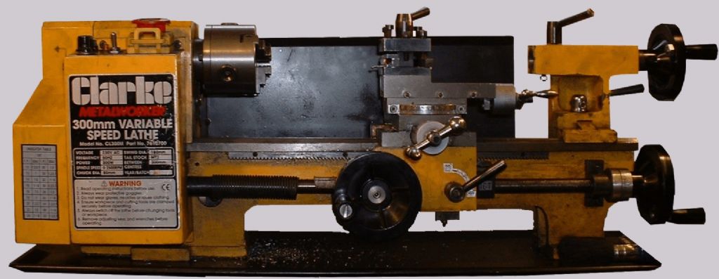
Photo 1: Clarke CL300M
Enjoy more Model Engineer reading in the monthly magazine.
Click here to subscribe & save.
The Original DC Motors
My Clarke CL300M mini-lathe was my first lathe (photo 1). Unfettered by experience or education, I assumed that anything I could fit in it, I could turn in it. One of the side effects of this approach was a burnt out motor. I now know a lot more about turning, and machine tools in general, and appreciate that just because you CAN take a deep cut at large diameter (photo 2), doesn’t mean you SHOULD! In particular, the slow speeds needed for such work reduce the ability of the motor’s built in fan to keep it cool.

Photo 2: An ambitious turning task.
It took me some time to source a replacement motor, and when I got it I treated it a little more gently. After several years it went pop too. I was able to bodge a repair and give it a semblance of life, although low speed running suffered.
I obtained a third motor second-hand from a classified advertisement in ME, just in case. Eventually, the second motor became too far-gone for further running repair, but to my dismay I found the spare motor was also blown. My sincere thanks go to the kindly old gent who sold it to me. I botched this third motor and got things, just about, running again.
Not long afterwards, I was machining some particularly intractable steel, and a long snake of swarf found its way into the control box. End of motor controller board. At this point, I began to despair. New motors were expensive, and now I needed a new board as well. However, I was more familiar with the mechanical capabilities of my lathe, and I wasn’t very keen to keep fitting motors that wouldn’t let me use it near its limits. I saw that a new version, with a bigger, more robust, brushless motor was available, but the new motor won’t fit the old style lathes. Then I realised that I had a lovely old 1/3 HP Hoover Motor (photo 3), perhaps fifty years old, given to me by a colleague who had once run a business installing motors several hundreds of times as powerful!)

Photo 3: Single-phase Hoover motor
Converting to Single Phase AC
A quick check, and the old single-phase motor was found to run as smooth as silk. To get up and running as quickly as possible, I enlisted my milling machine as a sort of vertical lathe. With this I made a pair of basic pulleys. I also milled some plates to hold ball races, allowing me to fit a countershaft to fit in place of the lathe’s original motor.
The design of a mini lathe makes it almost impossible to devise a direct drive to the lathe spindle, however, this problem was easily overcome by replacing the motor with a countershaft. This approach has the advantage of retaining the 2:1 reduction provided by the existing toothed belt drive from the motor to the spindle and the high/low gearbox in the headstock. This arrangement can be used to allow any alternative motor to be used, you just need a matching pulley (or pulleys) on the motor and countershaft.
The countershaft itself, (photo 4) is really simple, although it needs to be rigid and accurately aligned to ensure reliability and long life. A steel base has two thick aluminium alloy end plates secured to it with countersunk screws; the end plates are bored for ball races in which runs a good sturdy shaft.

Photo 4: The simple countershaft
This assembly completely replaces the motor, having the toothed drive pulley fitted to the outboard end and a suitable pulley (or pulleys) for the drive from the motor in the middle. It is fixed in the same way as the motor (photo 5), allowing easy adjustment of tension in the toothed belt. Just remember to fit the belt before assembling the end plates to the base and fitting the countershaft to the lathe (don’t ask!)

Photo 5: Countershaft fitted in place of the motor
With one pulley fitted to the motor and the other to the countershaft, I was able to use the lathe. The first task was to make some multi-step pulleys. This gave me a six-speed drive, or twelve speeds with the 2:1 built in ‘back gear’. The motor was mounted on a hinged wooden plate to allow belt changing; a hefty weight on top of the motor maintained belt tension! I built a no-voltage switch arrangement, and fitted it inside the existing lathe control box.
For anyone interested in copying this arrangement, which does work surprisingly well, my pulleys were turned from aluminium blanks. The countershaft pulleys had overall diameters of 3 1/4, 2 1/4 and 1 5/8 inches. I think the motor pulleys were about the same as the two smaller motor pulleys, but I have either lost or ‘recycled’ them. Together with the ‘high/low’ gear change built into the lathe, this gave me ten speeds (two were effectively duplicated) between 140 and 1100 rpm. The figures in table 1 are actual measured speeds.
Table 1: Speeds available using belts and pulleys.
|
|
Motor Pulley |
|||||
|
|
Large |
Small |
||||
|
Countershaft pulley |
S |
M |
L |
S |
M |
L |
|
HIGH |
1098 |
650 |
478 |
743 |
444 |
326 |
|
LOW |
479 |
184 |
142 |
479 |
283 |
208 |
This arrangement was only meant as a stop-gap, but to my surprise I found it easy to use and did not miss variable speed – just the lack of a really low speed. Interestingly, I found that despite the nominal power of the old motor (photo 6) being nominally the same as the original DC motor, I found that in practice it was more powerful. I could not use all the power available, however, as the 1/4” plastic belting I had used slipped under power, unless the tension was increased to the point where the joint would fail after a few hours.

Photo 6: The Hoover motor's information plate
Despite these minor annoyances, by carefully remembering to drip a little oil in the cups each time I used the motor, it gave me good service without a single hiccough. There was one worrying moment – on the ME forum someone reported that an almost identical motor caught fire as the rubber insulation on the wires had perished. I checked my motor, and was relieved to discover that the wiring was PVC insulated and in sound condition. The mains lead had rubber insulation, still in good condition but I replaced it as a precaution.
Eventually, though, I decided that I ought to go the whole hog and fit a three-phase motor with a variable frequency drive. This would let me get the absolute best out of the lathe, particularly as the constant-torque characteristic of a VFD drive would be ideal for low-speed work.
Let’s Do It – Fitting a 3-Phase Solution
After researching the options, I decided on an inverter and motor combination from Transwave in Birmingham – not least because I could collect it and pick their brains as the same time. I asked about moving up to a larger motor, but Their advice was that a similarly rated 370 W (0.4 HP) 3-phase system would, in practice, give much better performance than the single phase 1/3HP motor because of the steadier application of power.
You can control the inverter from its built in control panel, but the controls are small and, unlike consumer goods, it is easy to remove the front panel and access live wires. This is fine for a unit fitted on the wall, out of the way, but not for one on or near the lathe and ‘in the line of fire’. This is common need, so inverters are generally designed to operate with a remote control box, running off an isolated low voltage supply.
Transwave sell ‘remote pendants’, but being on a budget and confident I had most of the requisite bits already, I asked about making my own and after querying my level of electrical experience, they said I should be quite capable of making my own, and so it turned out.
I concentrated on getting the inverter, motor and control box working, before fitting everything to the lathe. A better sequence might have been to fit the motor to the lathe at the beginning, as this would have allowed more thorough testing as I went along. In the end, everything worked fine when fitted to the lathe, but I will describe the mechanical operations first.
VFD Version 1: Countershaft Drive
As mentioned earlier, I found the round belting unsatisfactory when I needed to get a decent amount of power into the lathe. A normal v-belt would have worked better, but when I converted my milling machine to belt drive, I used a poly-v belt for simplicity, compactness and quiet running, and found it highly satisfactory on all three counts. As poly-v belts also have a reduced tendency to slip, compared to other types, one was the obvious choice for the new lathe drive. I used the same relatively light j-section belt for the lathe as the mill. I found it difficult to get detailed information on the power transmission capacity of poly-v belts, but through the ME forum I was able to obtain a data sheet and determine that a four-rib belt would be more than sufficient.
As the mini lathe has a built in ‘back gear’ – giving two speeds in about a 2:1 ratio, I decided that I would only need a single speed drive from the motor to the countershaft. This seemed to be the ample, although it would be a simple exercise to add a larger pulley to the countershaft to provide even more low-speed torque. I have never used the really high speeds available on the mini-lathe, so I decided on using equally sized pulleys. This gave me a speed range from a crawl up to just over 1800 rpm, with the inverter’s top frequency set to 65 Hz. Using the ‘low’ gear setting the range was up to 1000rpm, with the expected increase in torque.
I made a pair of pulleys from a piece of 1 1/2” EN1A Pb, the commonly available free cutting mild steel, (photo 7). This was straightforward enough. As I explained in my milling machine conversion, all that is needed is a tool, like a screwcutting tool, but with a 40-degree point. Grooving the pulley is then just four plunging cuts, each 2.0mm deep and at 2.34mm centres.

Photo 7: The poly-v pulley fitted to the motor
The pulley for the countershaft needed to be 1/2” bore, which gave me an opportunity to try out a 1/2” machine reamer I picked up at a boot sale for about 50p – it seems to have finished the hole nicely. The Motor pulley needed a 14mm bore, too large for me to ream and my nearest smaller drill is 13mm, so I bored out the centre. Both pulleys needed keyways cutting in them so I used my ‘Stan Bray’ slotting tool[1]. This handy device uses a simple ram and lever arrangement to move an HSS toolbit back and forth in a bore. In the absence of a shaping machine, it is much less stressful than trying to cut a keyway by winding the saddle back and forth.
I used this arrangement, together with a homemade pendant (photo 8) for about six months, and found it quite satisfactory, but despite the success of this arrangement, I still felt it was a bit of a jury rig.
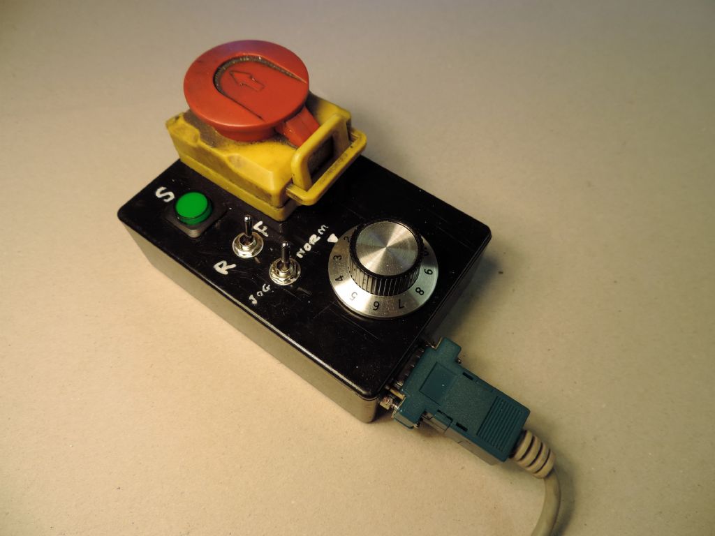
Photo 8: The simple pendant
VFD Version 2: Doing It Right
I wanted something that was a bit more professional. After considerable thought, I decided to change to direct drive to the spindle, and mounting the motor on the back of the lathe bed. In this new arrangement the motor is secured to a welded up frame from 19mm square steel tube pivoting on a bracket held in place using the screw holes for the old motor cover (photo 9). A steel bar, tensioned by a screw with a tommy bar, runs to the base of the lathe allowing the belt to be kept tight or loosened for pulley changes. I made a 1 3/4 inch poly-v pulley to fit on the back of the spindle (which meant cutting away much of the tumbler gear mounting plate – a cosmetic change). A 1 1/2 inch pulley on the motor gave me a top speed of about 1750 rpm. I discovered that this arrangement was a bit short on low end torque, so I fitted a two-step poly-v pulley to the motor to add a lower speed of 1200 rpm.
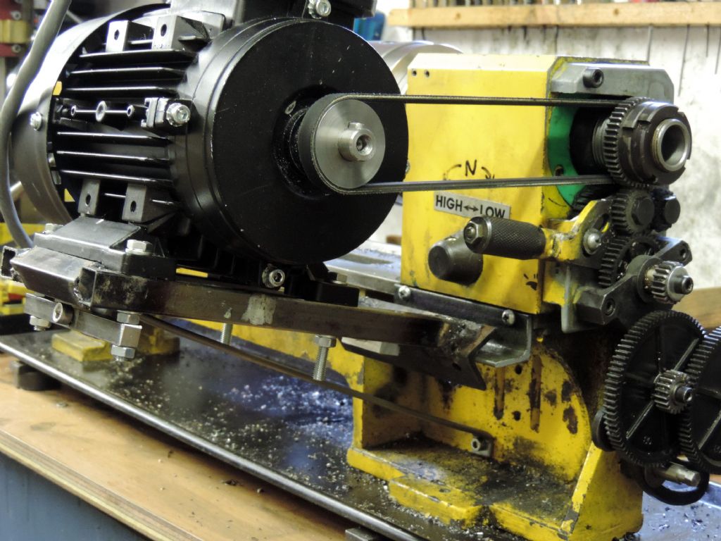
Photo 9: The new motor mounted on the back of the lathe
To complete the conversion, I dismantled my pendant and fitted a more sophisticated set of controls in the lathe’s original control box (photo 10).
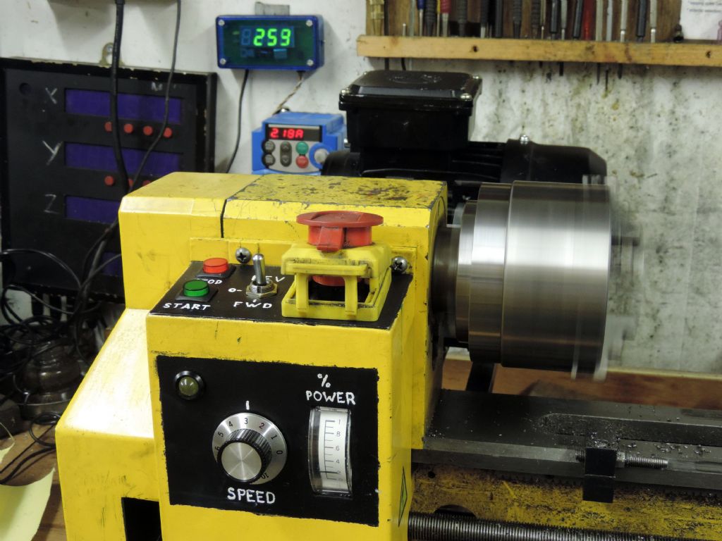
Photo 10: The new control box
The programming for the inverter described below reflects this new arrangement. In brief, the controls are:
- Emergency Stop – cuts all power to the motor immediately.
- Stop – motor decelerates to a gentle stop.
- Start – motor accelerates to speed.
- FWD – OFF – REV – hopefully self explanatory!
- Speed 0-10 – sets the frequency of the inverter and hence motor speed.
- When speed is set at 0 the motor enters jog mode and can be advanced using the start button for tapping etc.
- There are two indicators, a yellow LED showing the inverter is live and a power meter indicating 0-10, 5 is 100% of nominal power.
- The inverter display is set to show current consumption, and a separate tachometer shows spindle speed.
For those who would like to follow my example, I will give some detail of the motor and how I programmed the inverter. Please bear in mind that all this is unique to my setup, and you may need to make significant changes to suit other equipment.
The Motor
As mentioned earlier, the countershaft can be used with any type of motor and mine did sterling service with a 1/3HP Hoover single-phase motor and stepped pulleys. But I wanted the versatility of 3-phase variable frequency drive (VFD) and that meant a suitable 3-phase motor. Transwave recommended a TEC unit rated at 0.37Kw at 230V, 50Hz, delta configuration (photo 11).
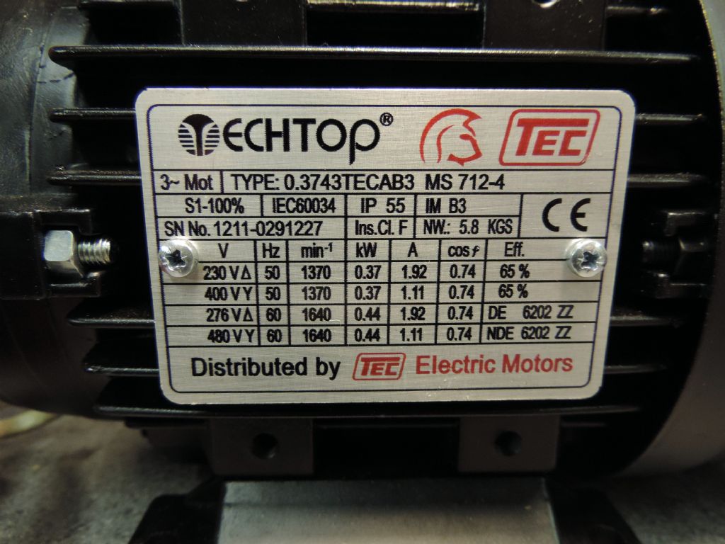
Photo 11: Specification plate for the 3-phase motor
As is usual with modern motors this is somewhat smaller than the old Hoover motor. The terminal connections are rather more accessible on modern motors, being in a box on top of the unit (as supplied – the base can be rotated). The motor was supplied wired in Y configuration (for a standard 415V 3-phase supply), and needed to be rewired to delta to run off the 240V drive. This involves moving three short bus bars within the terminal box, following instructions on the motor. With the motor I received a metre of heavy four-core cable colour coded for the three phases and earth. I used crimped on connectors for reliability. I was very careful that there were no shorts between any of the phases or to earth, and that the earth connection was securely fixed to the frame of the motor.
The Inverter
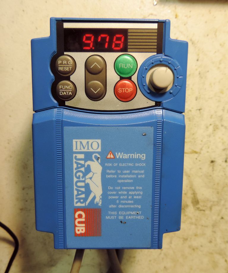
Photo 12: The IMO Cub inverter
The inverter I was recommended is an IMO Jaguar CUB3A-1 (photo 12). This happily runs from a domestic single-phase supply and outputs 3-phase 200-240V with a rating of 0.4kW or 0.5HP (photo 13). The overload specification is 150% for 1 minute, this is handy as it means it’s not the end of the world if you start a cut too deeply, for example. One advantage of an inverter is that it will reduce its output and try to keep things going, rather than just cutting out if you overload it.

Photo 13: The inverter specification plate
These are not a step by step instructions to using an inverter, it is a resume of what I did to set up and use my inverter and is intended only as guide to what to expect and consider if you choose to do the same. Hopefully, it will make it a little easier to understand what the manual is telling you. The connections I have given below may not apply to your inverter, even if it is a similar model, so check everything with the manual before proceeding.
Safety Considerations
The inverter manual starts with eleven pages of safety warnings. I have to suggest you read and understand all such information, and although I have extracted a few key points below, they are not a substitute for the manual. The inverter uses a mains supply and generates a high voltage drive to the motor. If you are not familiar with working with such voltages and the necessary precautions, find someone who is and seek their assistance.
I’m sorry to hedge around this article with so many warnings, but here is one more: Before wiring the inverter realise that its live parts are not made inaccessible in the same way as a piece of domestic equipment. It has covers that can be easily removed, without tools, to expose live wires. This means it must be mounted well away from anyone who might inadvertently open it or poke things inside the case, such as inquisitive youngsters. Typically, in an industrial application, the inverter would be mounted away from casual access, although access to programme or set the controls would not be unusual. An enclosure also serves to protect the inverter from liquids, dust and the like, but it should also be well ventilated to prevent overheating. If you have any doubts as to the security and safety of your insulation, I would suggest mounting the inverter inside a suitable enclosure that requires either a key or a screwdriver to open it.
The mains supply to the inverter and the motor should all be treated as potentially live, even after the inverter is switched off. The inverter converts mains to high voltage DC, and this is stored in a large capacitor. The manual suggests waiting five minutes after power off before ‘inspecting’ the unit, and I suggest the same wait should be applied before altering the wiring.
Finally, it is possible to override the ‘no voltage reset’ so the motor restarts automatically when power is reapplied. This is intended for applications like remote pumps and must NOT be used with machine tools for obvious reasons.
Connecting the Inverter to the motor and the mains supply
By gently prising off the main cover on the front of the inverter, I was able to slide up and off the ‘main circuit terminal block cover’. This revealed all the larger connections for the power supply and motor, as well as some advanced functions I did not use.
For the mains supply, I used an ordinary 13-amp plug on a heavyweight lead. It is important that this lead provides a secure earth connection, to which the inverter and the machinery are connected. There are two grounding terminals, marked ‘G’. These are used to connect the inverter to the mains earth, as well as to the frame of the motor, the enclosure and any other exposed metalwork. The line (live) and neutral from the mains supply I connected to the L1/L and L2/N terminals, respectively.
My inverter produces a 240V 3-phase output. This means the dual voltage 240V/450V motor had to be connected in delta mode as described earlier.
The output terminals are U, V and W and I connected these, together with earth, using the four-core cable I had attached to the motor. If the motor runs the wrong way, then two of the three motor supply connections should be swapped over. It is very important that the motor is earthed and that there is no way the supply or winding leads can short-circuit each other.
The terminals P1, P(+) and DB are used for a DC reactor and dynamic braking. These are used to provide braking, particularly of large motors, by attenuating the AC signal, or just shorting the motor coils. Believe me the inverter can stop small motors without such aid very effectively! The jumper bar between P1 and P1(+) must NOT be removed as we are not using such devices.
The terminals P(+) and N(-) are used for linking the high voltage DC supplies of several inverters, we will not be using these either. Don’t confuse the N(-) terminal with L2/N.
The power terminals should be connected using crimped on slotted-spade connectors, with insulated boots. This allows more than one wire to be safely and securely attached to some terminals, and helps prevent stray ‘whiskers’ of wire that could cause a short circuit. Like most people, I only have a very basic crimp tool but even this can be used to make secure crimps. The technique is to strip a short section of wire, as long as the tubular section of the crimp (5mm or 8mm). This is then threaded into the tube and the crimp closed using the notch in the crimp tool marked with the same colour as the connector. In principle, a sound crimp will actually create minute cold welds between the connector and the wire, and should be as secure as a soldered joint, but less liable to fatigue failure. Most crimping failures are due to insufficient force being used, so the welds do not form and the cable is not securely clamped.
Having made a nice neat job of these connections, I double checked them all, and replaced the main circuit terminal block cover. The mains supply could have been hard wired to a switched outlet, but I used an ordinary 13-amp plug. I would suggest the latter, for simplicity and flexibility, noting that the inverters rated demand is less than six amps from the supply.
I could now test the motor and inverter, using the controls on the front of the inverter. I had not changed any function codes, so RUN started the motor and STOP (believe it or not) stopped it. The speed ramped up and down gently over the default six seconds. You will notice that the readout does not show the motor speed, but the inverter frequency. The potentiometer should allow you to vary the output frequency, and hence the speed of the motor. Initially it was limited to 50.00 Hz maximum, but I soon changed this to gain a wider speed range, up to 65 Hz. Pressing the FUNC/DATA key while running switches the display between frequency, amps, volts and power.
In principle, I was now ready to go, but like most users I wanted to make more flexible use of the inverter, and to have a more robust remote control unit. This meant learning how to program the inverter and making and wiring up a remote control box.
Programming the Inverter
The inverter is programmed by inputting numbers into various parameters. There are many parameters, but fortunately they are all pre-programmed with reasonable default values and I only needed to change relatively few.
All programming was done in the same way. In brief, once in the menu system, ‘FUNC/DATA’ acts as a select button, and ‘PRG/RESET’ as a ‘back button’. The manual takes many pages to cover the various menus, but the following is a summary of the key points. Other inverters may have different systems, but the general principle of programming by entering a series of parameters seems to apply to most inverters.
- Turn on the inverter, it will enter ‘running mode’. Make sure the motor is stopped. In principle you can program the inverter when the motor is running; I’m not sure this would be a wise approach.
- Press the PRG/RESET button to enter programming mode. The LED monitor will typically show 1.F_ _ for the ‘function code’ editing option, or another letter if you last edited a parameter from another option. The up and down arrows can be used to select the other options 1E_ _, 1C_ _ and so on.
- Once you have the correct option letter, press FUNC/DATA. Pressing PRG/RESET again will take you back to running mode. The display will now show something like F 00. The up and down arrows can be used to select the parameter you need, say F 01 for ‘external frequency command’.
- To choose the parameter, press FUNC/DATA, or to return to the previous option press PRG/RESET. The display will now show a number between 0000 and 9999 or between 00.00 and 99.99. Only valid values for the parameter in question can be changed, and you can use the up and down arrows or the potentiometer to do this.
- To exit without changing the data, press PRG/RESET. To program in a new value, press FUNC/DATA and it will save the data and them the display will change to show the next parameter.
- Once you have programmed in all the codes you want to change, repeat pressing of PRG/RESET will return you to running mode.
I suggest that you follow my example, and only program the minimum number of parameters at a time, and then check that things still work. Often you can just change one parameter and do a check, but sometimes it is necessary to change more than one, as you may have to disable one function before you can enable another, for example.
If this all sounds long winded, it probably is, but it does allow you to programme a many parameters with only four buttons and three menu levels.
If you just want to check the data in the inverter and avoid editing it by mistake, you can go through the menu 1 function code letters, to menu 2. When 2.rEP is displayed, select it and you can then view all the parameters that have been altered (and only these) in turn – a great help to debugging if you have changed the wrong parameter by mistake. Don’t ask how I know.
Wiring up the control circuitry
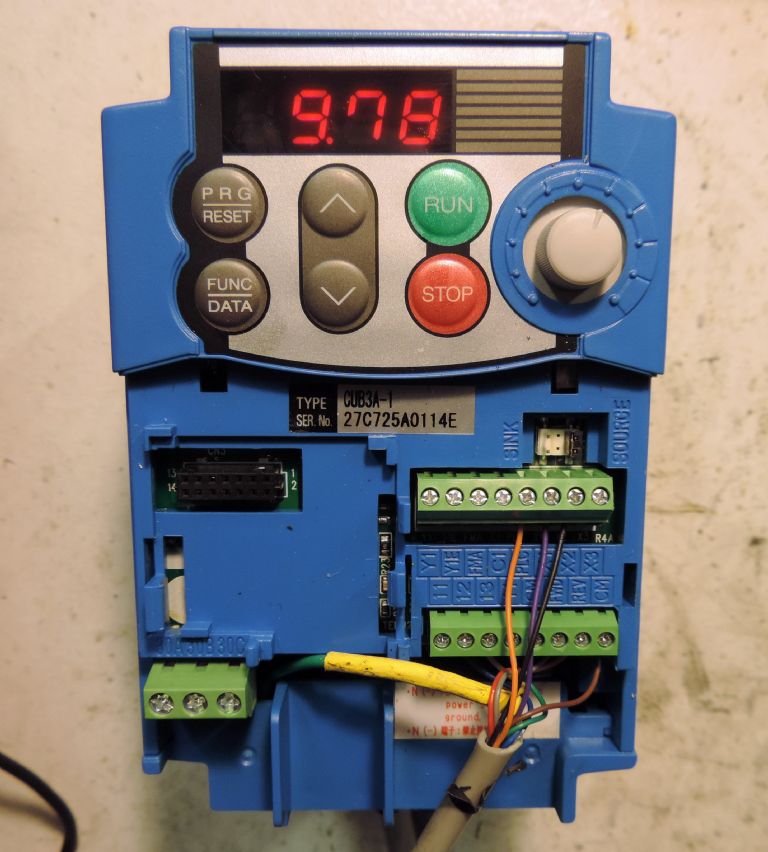
Photo 14: The inverter control connections
I wired up my own control circuitry, this allowed me to use additional features of the inverter (photo 14), note that I have now replaced the rather thin control wires with thicker ones. My wiring diagram is shown in figure 1, together with a basic parts list in Table 2. Be aware that it is, in some cases, possible to interchange normally closed and normally open switches, but you will have to change the parameters when programming the inverter.

Figure 1: Control box circuitry
Table 2: Control Box Parts List
- 10K Linear Potentiometer (Speed control) with a switch closed when fully anti-clockwise (for normal/jog).
- Skirted Knob, marked 1-10
- Single pole toggle switch on-off-on (Forward-Stop-Reverse)
- Large double-pole push button normally closed (Emergency Stop switch)
- Single-pole push button normally open (Start switch)
- Single-pole push button normally open (Stop switch)
- 0-1v moving iron meter (adjusted to 0-10V with series resistor)
- Yellow LED and suitable resistor for 10V operation.
- 10-core cable.
The control circuitry runs off two separate power supplies. There is a 10 volt system used for the speed control and some output signals, and a 24 volt system used for the other control inputs.
The low voltage terminals used for the control circuitry use high-quality clamp terminals that can be used with bare ended wires, although if you can get very fine crimp ferrules you can use them.
Motor speed can be controlled with either a current or a voltage between 0 and 10V. A suitable control voltage is easy to arrange, using a linear potentiometer of between 1 and 5 kohms between 0v and 10V. Why the option to use a current? If you have along run of wire, as may be the case with remotely controlled machinery, a control voltage may drop considerably due to resistance of the wires. On the other hand, if a control current is put into a long wire loop, the same current will flow along the entire length of the loop regardless of its resistance. As I doubt I will be more than a couple of feet from the inverter, a voltage is much more convenient to use.
I wired analogue common (terminal 11) to the anti-clockwise end of the potentiometer track (so 0v is the ‘off’ setting). I connected the 10V potentiometer supply (terminal 13) to the clockwise end (so that 10V is full speed). Finally I took the voltage input (terminal 12) from the wiper of the pot. I will show how I programmed the inverter to enable this external potentiometer shortly.
The other control signals use the separate 24V system. The way I have arranged my system is as follows. 24V (PLC) runs to the normally closed (N/C) stop switch. From the other side of the switch one wire goes to X1, this is the stop signal.
Another wire runs from this side of the stop switch, through a N/O start switch, to the centre terminal of the FWD/REV changeover switch. This is wired to switch the 24V PLC signal between FWD and REV on the inverter. This arrangement is needed to stop the motor switching on again as soon as I release the stop switch.
The jog mode selector switch is simply an on/off toggle switch connected between X2 and PLC.
Emergency stop or limit switches can be connected between PLC and X3. If normally open switches are used, they should be wired in parallel. Normally closed switches should be wired in series. The inverter will need to be programmed appropriately (see later).
Enabling the Speed Potentiometer
To enable the external potentiometer function F01 (frequency command) has to be set to 1. Other values are 0 to use the up and down arrows on the inverter, and 4 to use the built in potentiometer.
Remote control of starting and motor direction
I set F02 (running/stopping and rotational direction) to 1. This causes the motor to start running in the appropriate direction when either FWD or REV is connected to [PLC] (a +24V supply). My control box uses a three-way switch to connect +24V, via the ‘start’ push switch, to FWD and REV. The centre position acts as an off, preventing a start in either direction, but a simple two-way switch would be fine.
The terminals X1, X2 and X3 are used to control various functions by means of connecting them to either CM or PLC. In my case, the inverter was supplied configured so that they had to be connected or disconnected from PLC (+24V), although the manual assumes the default is CM (0V). The mode is chosen by the position of a jumper switch that should be in the ‘source’ position to use PLC for the control signals
I set E01 (terminal X1 control) to 1006. This sets the ‘hold function’ and keeps the motor running when the momentary start signal is disconnected from FWD or REV as long as X1 is disconnected from PLC. When stop is pressed X1 is connected and the motor will slow down over the time set by F08. The switches are arranged so that FWD and REV are also disconnected, ensuring that the start switch cannot operate when the stop switch is depressed.
Some machine tools do not use a start switch, just a three-position switch that selects forward, reverse or stop. If such a switch is used then the hold function is not required. The problem with this arrangement is that it is much harder to use such a three-way switch to jog the motor. A momentary start switch works much better for this.
Jog Mode
By programming E02 (terminal X2) to 8, the toggle switch connecting X2 to PLC turns jog mode on and off. With jog mode on the motor runs at a fixed speed while you keep start pressed, and stops when you release it. With a normally open switch, set E02 to 1008.
The speed of the motor in jog mode is controlled by the number programmed into C20 (jog frequency). I used 5.00, so the motor runs at 1/10 its normal speed. The default jog frequency is zero, so jogging won’t work until a value for C20 is entered.
X3 can be used for limit switches or an emergency stop’ by setting E03 to 1007 (for normally closed switches). This makes a switch to X2 into a 'coast-to stop' signal. Don't be confused by the name – it promptly disconnects the motor, ignoring any delay in F08, so it stops fast, instead of ramping the drive down over several seconds. This would be ideal to use with a foot brake. If your switches are of the normally open type, you will need to program E03 to 7 to reverse the logic on the input.
Some Other Functions
Reading the manual there are lots of bells and whistles. As it is set up the inverter seems to be programmed to automatically protect the motor from overheating by timing how long it has been running and at what level of power. It uses default values based on the motor specification, and I am cautious of changing these settings in the absence of detail information on things like motor thermal constants.
There are, however, a few other additional functions that can be changed to improve the performance and flexibility of the system with minimal difficulty. These are the parameters I think are worth looking at:
Motor Speed Functions
F03 (maximum output frequency) effectively sets the top speed of the motor. Most, if not all, motors you can buy are dual frequency (designed for both 50 and 60Hz) so one may as well use at least 60Hz. I have chosen 65Hz for the time being, however, I will probably raise it further as my confidence grows. It can be raised up to 800Hz or roughly sixteen times normal speed – unless using a motor and spindle designed for high speed use, keep the maximum speed much, much lower. When setting maximum speed, also bear in mind that some parts, cast iron chucks in particular, must not be oversped.
F04 (base frequency) should be set to match the frequency on the motor’s plate. If you have a dual frequency motor (50/60 Hz) set it to 60. This is because up to the base frequency the inverter will provide a linear voltage/frequency output, giving constant torque. Above this frequency it will output a constant voltage and hence constant power. If your motor is rated for 60Hz, take advantage of this and get the widest possible constant torque range.
F05 (base voltage) can be set to the nominal voltage on the motor plate. If this is done the inverter will use this voltage, instead of following variation in the supply voltage. This is not essential, and with bigger, heavily braked, motors its can cause overvoltage tripping, but it is needed for some of the very advanced motor features (which I will not describe).
F15 (maximum frequency limit) works like F03, but only applies to speeds set using a potentiometer. I set this to the same value as F03.
F16 (minimum frequency limit) defaults to zero, so only change it if you want a minimum speed – this could apply if you want other users not to run the motor very slowly for extended periods (which can cause overheating).
F07 (acceleration time) and F08 (deceleration time) are self-evident, you may feel the default 6.00 seconds is to long. I understand many users like a prompt stop, but that a time less than two seconds can cause overvoltage tripping, requiring a reset to be carried out. Personally I prefer the gentle speed up and down, noting that motors started gently are less likely to overheat from repeated starts.
Other Extra Functions
There are several other useful functions, that won’t affect how the motor runs, but may still be useful.
E43 can be used to programme what the LED display on the inverter shows. By default it shows the output frequency and switches between this and the output current when you press
By programming E48 you may get values other than drive frequency, that may be more useful, but it is not a simple process. If you program E48 to 4 you can get the monitor to display load shaft speed. This also requires programming E50 with a coefficient which equals the speed at a known frequency, divided by that frequency. So if a lathe mandrel rotates at, say, 1750 rpm at 50Hz, program E50 with 1750/50 = 35, and E48 to 4, and the display will show the lathe speed – unless, of course, you engage back gear!
There are other options for the display, but be warned, the manual is very poor in explaining how they work!
Another interesting function is F31. This can be used to send an analogue signal to terminal FMA (analogue monitor) of between 0V to 10V, in line with various parameters. This can be used to display frequency, voltage, power or current on an analogue voltmeter (10V full scale, or you could use a suitable dropper resistor). The meter should be connected between the terminals FMA and 11 (analogue common), the latter as used for the ‘low side’ of the speed potentiometer. It is possible to scale the output using F30, between 0 and 200%, so if you have a 1V meter, for example, programF30 to 10.
Finally, the inverter also produces some on/off status signals. These can be used to control a transistor switch or a changeover relay. Because the relay is rated at just 200,000 operations, it should only be used for ‘occasional’ alarms or signals. In contrast, the transistor switch can be used for regular ones. Both the relay and the transistor are electrically isolated from the inverter and its control circuitry, and so can be used to communicate with other equipment.
The relay normally links terminals [30B] and [30C], but when there is an ‘alarm condition’ it switches to join [30A] and [30C]. The relay is rated 250V AC 0.3A, or 48V DC 0.5A.
The transistor is an opto-isolated NPN type with its collector attached to [Y1] and its emitter to [Y1E]. It is a low power type rated at 27V 50mA.
E20 is programmed to assign signals to the transistor, and E27 to assign signals to the relay. An example signal for the transistor might be 1 (frequency equivalence), could be used to light an indicator when the inverter is running at the selected speed.
For the relay, a use might be to light a warning indicator as an overload early warning. The three parameters for this warning are not simple, to calculate, but fear not! They are automatically programmed by default, based on standard values for a motor that matches the rating of the inverter. If you have purchased the motor and inverter as a matched pair, you should not need to change these settings.
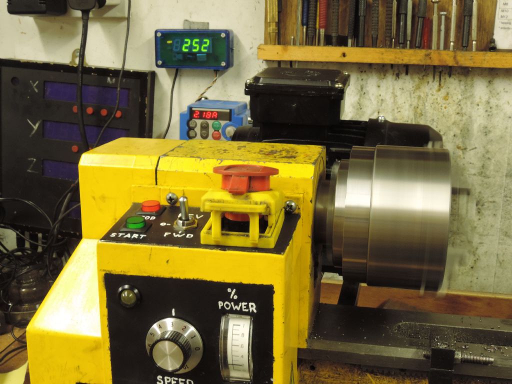
Photo 15: The lathe running under inverter power
In Conclusion
The IMO Jaguar Cub inverter is a spectacularly complex device, with a more functions than you can shake a stick at! Most of these are so that it can control and monitor motors in a wide range of applications, from food mixers to fans, let alone machine tools. Others are tied up with industries need for quality control and process monitoring – for example reporting on the lifetimes of various components, or how long a cooling fan has been running. The mind boggles to think what ‘advanced’ inverters are capable of.
The basic needs of a model engineer are to be able to stop and start a motor, and control its direction and speed. This can be done very simply using the built in inverter controls. A little more effort allows the controls to be located on a remote pendant, or a machine mounted control panel, and for built in stop switches and brake switches to be wired in as well. More ambitious users will look at programming the display, or controlling indicators. The truly obsessed will go beyond this brief introduction and start playing with things like torque boost and thermal constants.
It is important to know, therefore, that the inverter comes with many of its functions programmed by default. One sold in the EU will typically assume that it will control a 50Hz motor, with the same rating as the inverter. This means that you can leave most of its settings well alone, and it will still do sensible things, like working out if your motor is likely to overheat.
Good luck, observe the safety warnings and precautions, take one step at a time and enjoy being able to have a power system for your machinery that exactly meets your needs.
Neil Wyatt
[1] Stan Bray, Useful Workshop Tools, Workshop Practice Series No. 31,


