Phil and Dave, I've limited experience with inverters, just having the one running at the moment on my Centec, but with a couple more ready to wire up when I get the chance.
The easiest way for me to check out windings is to use a "megga" (or megohm meter), mine can be set up to measure high resistances, at 240, 500, or 1000v (i.e. to seek winding to earth, or winding to winding faults)
It can also be set up to measure very low resistances (i.e. earth continuity, and in this case coil winding continuity)
The combination of the two readings should help point to any faults in the motor, other than winding polarity reversals. It won't help deduce whether a motor will work with a digital inverter happily, even if it tests OK
N.B I'm not a qualified sparky, though I have produced the odd spark or two over the years. 
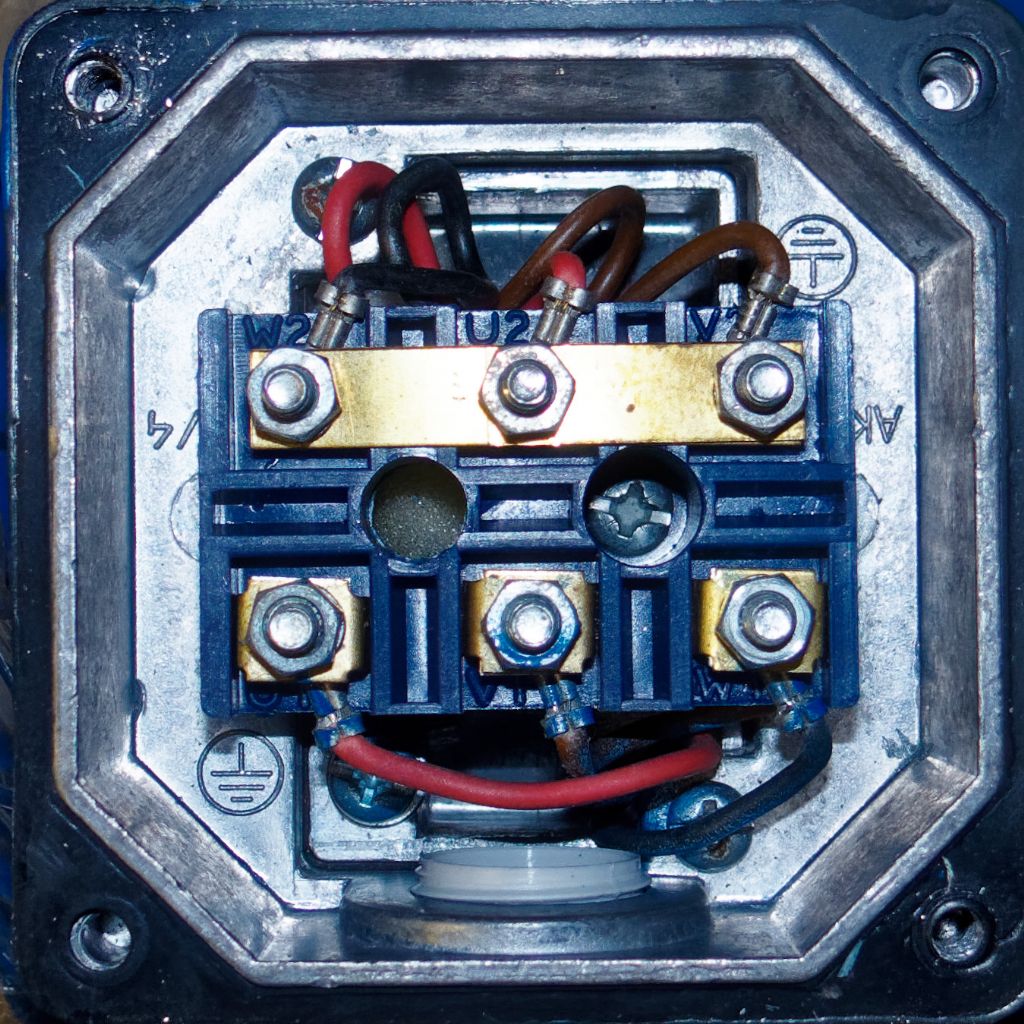
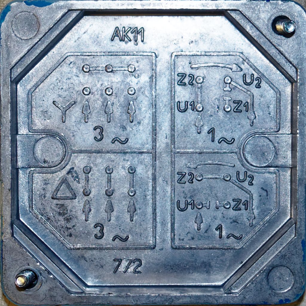
I've just been out to the workshop and taken the cover off a brand new motor, bought to go on the Dore-Westbury mill; I've not had chance to fit it yet. The photos below show the interior terminal strip and the cover plate which shows where to fit the bus bars for 415v Star configuration, or 240v Delta config. As you can see, it's presently wired for Star, so I'll need to re-jig it for my 240v output inverter.
In this case, rather than A~B~C the windings are labelled U~V~W. so the following, and my previous diagram may be leading you the wrong way up the garden path.
The top row of bus bars are configured to give a star point, commoning all the coil-2 terminals together, with 415v 3 phase to each coil-1 terminal.
They are numbered left to right out of alphabetic sequence W2~U2~V2 but that doesn't matter for Star as they are commoned together. (It's to make it easier to re-config for Delta)

The bottom row are labelled in sequence U1~V1~W1. As you can see, winding U ~ red, V ~ Brown & W ~ Black
The "1" terminations have even been dabbed with blue paint/lacquer.
Now for 240v Delta, the bus bars are oriented North/South, as per the diagram in the lid below. (We're only concerned with the left hand two diagrams, as the RH ones are for single phase.)

Thus the common points are, from Left to Right;
U1 ~ W2 assuming U=A, V=B & W=C I think this equates to A1 ~ C2
V1 ~ U2 """"""""""""""""""""""""""""""""""""""""""""""""""""" B1 ~ A2
W1 ~ V2 """""""""""""""""""""""""""""""""""""""""""""""""""""C1 ~ B2
Which is what I think my previous diagram shows,
N.B I may be in error assuming an A~B~C motor is equivalent to U~V~W one, which I accept may well not be the case.
Does your cover plate have a similar diagram, if so, make sure you follow that in case AEI use different terminology for their windings; I can't find anything on the net about their config.
Good Luck
Bill
Edited By peak4 on 17/12/2017 21:02:16
 Neil Wyatt.


