Lathe vibrations

Advert

Lathe vibrations

Viewing 25 posts - 26 through 50 (of 88 total)
  • Author
    Posts
  • #331987
    Johnboy25
    Participant
      @johnboy25

      A lot of the comments and suggestions have been made on this already but has the VFD got an Autotune function? I use makes like Parker SSD, ABB Drives, Telemecanique & Mitsubishi types on my machines. These are usually aquired off eBay. As paying full price it a bit costly to say the least! 😳

      John

      Advert
      #332088
      Peter Smith 25
      Participant
        @petersmith25

        Hi all

        For info the windings have letters and numbers on each. I have connected

        B2 to C1,

        A2 to B1 and

        A1 to C2.

        Each of the inverter utput wires connects to each of these pairs. Does this appear to be correct?

        Thanks Peter.

        #332092
        Mike Poole
        Participant
          @mikepoole82104

          That is what I would have done. The acid test is does it run smoothly? If not then it won't take long to swap each coil round one at a time and see if it makes a difference or you could run through the process linked to in a previous post. Most inverters will not need too many parameters to be set from the out of the box setup just to run the motor.

          Mike

          Edited By Mike Poole on 14/12/2017 21:04:46

          #332101
          Peter Smith 25
          Participant
            @petersmith25

            Hi Mike.

            Sorry to ask stupid questions, do you mean swoping the 3 inverter output wires around, as i initially did this to correct the rotation of the motor (swoped two of the three wires). I have wired the inverter input control into the lathe switch gear. As such the start, stop and forward/reverse switches on the lathe control the input switches on the inverter. The only external change to the lathe is the addition on a 10k pot.

            Regards Peter

            #332105
            peak4
            Participant
              @peak4

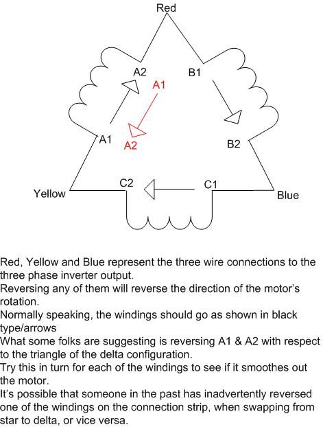
              Peter, before I read your last post, I've tried to answer that one in a PM. The suggestion isn't to swap the supply wires round, rather swapping the orientation of one of the sets of windings which form one side of the triangle of windings in delta configuration.

              Bill

              #332107
              peak4
              Participant
                @peak4

                I hope this copies OK and explains the thoughts of some on here.

                3 phase diagram

                #332129
                Mike Poole
                Participant
                  @mikepoole82104

                  Very well explained Bill, I think this has to be tried as it at least needs to be ruled out of the possibilities.

                  Mike

                  #332134
                  Peter Smith 25
                  Participant
                    @petersmith25

                    Hi All

                    Thanks to Mike and Peak4, very well explained.

                    I've just come out of the garage after working in the base of the lathe changing around the wiring as suggested.

                    On each of the winding wire changes the motor ran much slower, rougher and grumbled as if it had a knackered gearbox.

                    So I think the wiring was originally correct. As you can imaging after all i have done to this lathe, i think i would be better off sat in the pub with a glass of real ale!

                    I'll now have the day off it and i think change the motor which brings me back to, do you think 1 and a 1/2 hp motor is adequate for the lathe and if not what would you fit.

                    Thanks again for your help, and have a good weekend

                    Peter

                    Edited By Peter Smith 25 on 15/12/2017 10:57:40

                    #332149
                    Mike Poole
                    Participant
                      @mikepoole82104

                      To recap where we are upto:

                      The motor used to run ok on a previous converter setup.

                      The motor bearings have been replaced.

                      The rotor with pulley fitted is well balanced.

                      The motor windings are wired correctly and no winding is incorrectly labelled or reversed.

                      The motor produces a vibration with the belt removed.

                      The inverter can run a smaller motor smoothly but the same settings do not work on the original motor.

                      An alternative inverter produces the same symptoms.

                      —————————————-

                      Do you have the details from the motor plate? ( ideally a picture). Does the plate show the delta connection voltage to be around the 230v area and star 415v. What is the Full load current for each configuration and can the inverter supply that current?

                      Mike

                      #332156
                      Mike Poole
                      Participant
                        @mikepoole82104

                        Using the smaller motor of 1.5hp may well be ok, you may have to use some longer ramp times to get things moving but if the drive train doesn't need too much of the 1.5hp you may be ok as long as you don't work it too hard. I expect the frame size of the motor is smaller than the original so will need a packer to get the shaft height correct or a longer belt if there is not enough adjustment. The shaft diameter is probably smaller so a new pulley may be easier than a sleeve setup.

                        Mike

                        #332165
                        Ian S C
                        Participant
                          @iansc

                          It would be helpful to see if the balance of the phases of the inverter goes off at the load of the 3hp motor comes on, one or two of the phases may not be up to the work.

                          Ian S C

                          #332204
                          Peter Smith 25
                          Participant
                            @petersmith25

                            Hi Mike and guys

                            Sorry i've tried to upload photos but failed miserable, so the motor plate info is

                            Type D90L

                            V220/250-380/440

                            A 8.7/5 3HP DE 125P

                            1410 RPM HZ 50 IC1258

                            Inverter info is not listed in the printed sheets but on the side of the inverter is a sticker with

                            Input:AC 1PH 200-240V 50/60HZ 20A

                            Output:AC 3PH 0-240V 0-200HZ 3HP.

                            Hope this helps

                            Regards

                            Peter

                            #332222
                            isimbard brunel
                            Participant
                              @isimbardbrunel74810

                              Before yo go spending more money I would look at the torque boost setting on your inverter – after all pressing a few buttons won't cost you anything, Set the torque boos (parameter F09 on the jaguar cub range of inverters) t to 'constant' (option 3 and I imagine the problem will vanish like the Scotch Mist. Stop buying unknown cr%*and buy from somebody trustworthy who can support you!

                              IKB

                              #332331
                              Peter Smith 25
                              Participant
                                @petersmith25

                                Hi Isimbard Brunel

                                Thanks for your input.

                                Would altering the torque setting (F13 on my inverter) effect the vibration which is evident at all motor speeds, with and without the drive belt fitted? The vibration is evident running the lathe, taking light cuts or even cuts of 100 thou per side (which it will do without much problem).

                                Thanks

                                Peter

                                #332368
                                Brian Sweeting 2
                                Participant
                                  @briansweeting2

                                  Whilst appreciating the potential electrical hiccups is there any mileage in there being a problem with the bearings?

                                  I know that you have checked the balance of the rotor and pulley but this was outside of the motor frame.

                                  Are the bearings tight and square on the shaft?

                                  Are they a good fit in the motor casing itself? Did the casing go back together in proper alignment?

                                  Just clutching at straws here.

                                  #332369
                                  Peter Smith 25
                                  Participant
                                    @petersmith25

                                    Hi all

                                    As an experiment, i changed the inverter torque control settings to 3,7, and max 10. None of them made a scrap of difference, so that's it for this motor. Tomorrow i'll pull the lathe away from the wall, (no mean feat) and swope the motor for the 1.5 hp.

                                    I'll let you know the outcome.

                                    All the best

                                    Peter

                                    #332370
                                    Peter Smith 25
                                    Participant
                                      @petersmith25

                                      Hi Brian

                                      I checked the rotor assembly balance as in desperation i changed the motor bearings. They were very good and a good fit in the housings. With no play when assembled and the rotor spin freely by hand. I split open the old bearings and the were also in good condition.

                                      Thanks for your thoughts

                                      Peter

                                      #332374
                                      Brian Sweeting 2
                                      Participant
                                        @briansweeting2

                                        Just keep an eye on the motor temperature when running at reduced speeds, the 1.5hp one that is.

                                        #332386
                                        isimbard brunel
                                        Participant
                                          @isimbardbrunel74810

                                          Good Morning Peter

                                          Yes, torque boost will affect motor vibrations regardless of speed Which is why I said to make it constant.

                                          If you have the option on your inverter to make the torque boost constant or even completely disable it I remain confident that this will solve your problem.

                                          The motor is constantly trying to respond to any changes in load characteristics. .So, no bel) – smooth running (inverter not trying to do anything)

                                          Refit belt-,motor now has varying load (gear selected, power feed' oil viscosity, tool resistance) Inverter is now 'chasing' load and 'hunting for perfect setting. This 'hunting is constantly changing causing the vibration. If you can disable the inverter trying to do this it will all run smoothly.

                                          This scenario has been reported many times in the past on lathes of all kinds with problems ranging from strange patterns on finished work to motors sounding like badly set up Diesel engines!

                                          IKB

                                          #332388
                                          Johnboy25
                                          Participant
                                            @johnboy25

                                            IKB – that’s interesting… that’s a good point that you’ve raised. I can see the reasoning behind your thoughts/experience. I’ve never had to ‘play’ about with torque setting in the applications I’ve had experience with but well worth committing to memory..

                                            John

                                            #332411
                                            Peter Smith 25
                                            Participant
                                              @petersmith25

                                              Hi IKB

                                              Thanks for your response, the torque control setting was set at 0, so i reset it at 3, tried the lathe, then 6, then 7 then maximum, 10. All made no difference to the the vibration which can be felt wherever you touch the lathe or even the motor body. It isn't a rumble like i found when reversing the winding wires, but is more a tremour. I think i understand your explination, the fault is evident with or without the drive belt fitted and does not change if you take a cut.

                                              As you can probably gather, i'm becoming fed up to say the least of this lathe, i'm quite reasonable as a self taught engineer and only use it for fun, however having to tape the finished work piece to get a decent finish makes me want to look elsewere for a hobby.

                                              Thanks again for your thoughts

                                              Peter

                                              #332425
                                              John Haine
                                              Participant
                                                @johnhaine32865

                                                As the motor used to run smoothly on a phase converter (presumably the type that uses inductors and capacitors to generate pseudo-3 phase), but seems to vibrate when driven from both of 2 different inverters; and you have verified that the winding's are in the correct sense; the only conclusion can be I think that the motor doesn't like running with an inverter. Apparently older motors may not be suitable, I don't know why, in my experience both the older motors I have used were fine. So the only option seems to be to use a motor that does!

                                                You say that the 1.5 hp motor you have runs quite smoothly on an (both?) inverters, so the question that you asked is whether you could use that for the lathe? Well there are three reasons why you might not.

                                                One: is it the right speed? To keep to the same speed ranges it would be best for the motor to run at the same nominal speed – the AEI motor was probably 4 pole ~1450 rpm, so if the new motor is the same that's OK.

                                                Two issues with power: is the lathe so big that just its inherent friction absorbs too much power? Well, I doubt it somehow if it fits a standard sized workshop. And: how much power is needed for the cuts you are likely to do? Unless you are removing industrial production amounts of metal I would have thought that for amateur work 1.5 HP is quite enough.

                                                #332429
                                                Phil Whitley
                                                Participant
                                                  @philwhitley94135

                                                  According to my Brooks motor book, the connections for Delta running should be A1>B2 B1>C2 C1>A2. The windings must be oriented correctly, which is why they are marked with 1 and 2 indicating the correct (winding direction) connection. there would be no point in this method of marking if reversing one set of coils reversed the motor, it does not, reversing two of the incoming supply lines reverses the motor. The Motor is a dual voltage motor which runs on 380/415 connected in star, and 220/240 when connected in delta. motor noise can be caused by loose windings or loose stator or rotor laminations, but given the motor was running correctly, my feeling is that it is incorrectly connected. Reconnect it as above and report back please! AEI motors from the seventies did have a bit of a bad name, but it WAS running ok, so its got to be incorrectly connected, or there is a "dirty" phase from the inverter.

                                                  Phil

                                                  #332431
                                                  Peter Smith 25
                                                  Participant
                                                    @petersmith25

                                                    Hi Phil and all

                                                    Thanks for your input, i won't repeat myself as your ideas have been tested and results noted earlier in this thread.

                                                    This afternoon, i removed the motor and wired it up simply sat on the garage floor. The vibrations felt throughout the lathe were now felt in the body of the electric motor. So it appears this motor does not like my inverters.

                                                    The 1.5 hp abb motor, shaft height, shaft diameter and key size are the same as the 3hp AEI motor, so no guessing my next move!

                                                    I'll keep you informed.

                                                    Regards

                                                    Peter

                                                    #332437
                                                    Phil Whitley
                                                    Participant
                                                      @philwhitley94135

                                                      OK, thanks for that, when I read the previous posts it showed another connection set, which was incorrect. A1>B2 B1>C2 C1>A2 and incoming lines to each junction for Delta is the only pattern that will work The diagram above does NOT use this pattern, and is incorrect.. You may well have trouble starting the lathe in higher speeds, with a smaller motor, unless you have a clutch.

                                                      Phil

                                                    Viewing 25 posts - 26 through 50 (of 88 total)
                                                    • Please log in to reply to this topic. Registering is free and easy using the links on the menu at the top of this page.

                                                    Advert

                                                    Latest Replies

                                                    Viewing 25 topics - 1 through 25 (of 25 total)
                                                    Viewing 25 topics - 1 through 25 (of 25 total)

                                                    View full reply list.

                                                    Advert

                                                    Newsletter Sign-up