Lathe unwanted taper

Advert

Lathe unwanted taper

Home Forums Beginners questions Lathe unwanted taper

Viewing 25 posts - 26 through 50 (of 55 total)
  • Author
    Posts
  • #326433
    ChrisB
    Participant
      @chrisb35596

      Dont think it was material flex, I had a dial rigged and pushed the bar by hand to get a feel of how much deflection I would get, the cuts I was taking were in the order of 0.02mm, very shallow. As for tooling I used both positive and neutral back rake angle tooling, with no noticable difference.

      This morning purchased some mild steel round stock and other material for some projects I have in mind, if I find time this afternoon I'll turn a test piece and check again

      Advert
      #326455
      David Standing 1
      Participant
        @davidstanding1
        Posted by Speedy Builder5 on 09/11/2017 08:08:40:

        200 mm of 20 mm bar – That would deflect by that amount if you applied 1/2 a Kg on the end of the bar, so it is likely that it would whip/ bend whilst you were turning it. You say light cuts, but the tool still loads the end of the bar. An accurately aligned tailstock and centre was the way to go.
        BobH


        I was sceptical about this (that a 1/2 kg downward force would cause the bar to deflect by 0.2 mm, or .008" ) but whilst the common reaction on t'internet is to fire off an opinion, correct or not, I decided to conduct a real world test.

        I have not got a piece of 20 mm aluminium bar that long in stock, but I do have 3/4", i.e. 19.10 mm.

        I chucked this up in my Boxford, set up a Kennedy DTI that measures .0005" increments at 8" from the chuck, and applied a 1/2 kg piece of brass rod on top of the ali at 8" from the chuck.


        Result? Less than .001" deflection, and this is 3/4" (19.1 mm) bar, so deflection of a 20 mm bar would be less.


        In addition, Chris taking a light lengthwise cut will not result in all the force of the cutting tool deflecting the bar.

        Some (or most) of the force of the cutting tool is in a lengthways direction, so would not deflect the bar sideways by all of the force of the cutter.

        Noting the above, I would say that despite not using a tail centre, the taper turning is NOT caused by the bar being unsupported at the tailstock end.

        I'm not saying it should not be supported, merely that I don't think this is the cause.


        I would go with Jimmy's theory, that the headstock is likely not in line with the bed, or Hopper's theory that the lathe bed is not level (ie, it has a twist)


        Edited By David Standing 1 on 10/11/2017 13:55:38

        #326605
        ChrisB
        Participant
          @chrisb35596

          This morning I had a go turning another test piece from the mild steel I bought yesterday. Turned a 1" O/D piece over 150mm. First off I turned 2" from one end to remove the black scale and turned it around in the chuck to have a proper seating, then I tried to machine the rest of the bar (about 150mm) but it chattered badly, even with a light cut, had no such issues with aluminium.

          Probably aluminium being soft complies with the tool and shears without deflecting much, steel being harder deflects, or so it seems to me….

          Anyway I supported the free end with a revolving centre and took multiple cuts, the results are the same as those I had with aluminium, or a bit better difference of about 0.01 – 0.005mm over 150mm, not bad I guess.

          The only issue I'm noticing is that when I tighten the tailstock barrel lock, the test piece deflects and then when I machined it I got a taper (0.05mm difference wider at the chuck end) If I just snug the lock it will be fine.

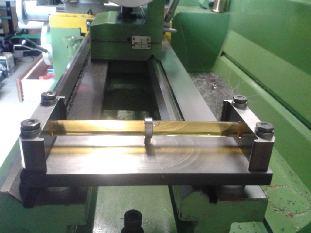
          Also, checked the bed for level, the twist it originally had is much reduced now, initially the level was reading out of scale in opposite directions, now it's still reading some twist but much reduced (a normal spirit level will read the same at both ends)

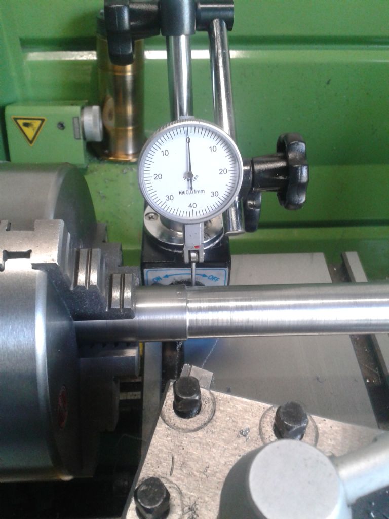
          20171111_093006.jpg

          Chuck side reading close to 0 after test cut

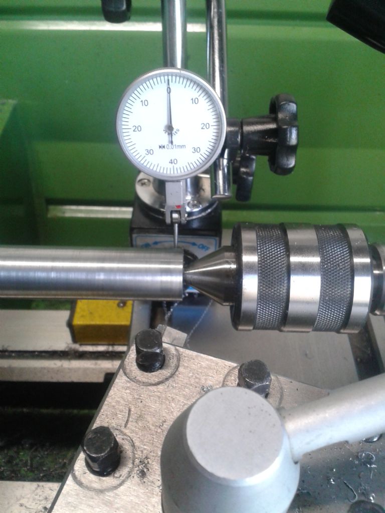
          20171111_092853.jpg

          Tailstock side reading 0 after test cut

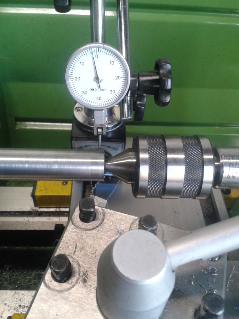
          20171111_092903.jpg

          Deflection when tightening the tailstock barrel lock, get greater the more I tighten up to 0.05mm max

          20171111_093237.jpg

          Level at tailstock end

          20171111_093627.jpg

          Level at chuck end, a bit off but I think it's good enough, it starts to get tricky to get the bubble centered at both ends!

          #326608
          Anonymous

            If you're measuring the work "diameter" variation by running a DTI along the work then all bets are off. You need to measure the diameter with a micrometer to get a proper picture.

            Andrew

            #326614
            john carruthers
            Participant
              @johncarruthers46255

              Try another chuck first? or turn between centres?


              Edited By john carruthers on 11/11/2017 10:28:00

              #326619
              David Standing 1
              Participant
                @davidstanding1
                Posted by Andrew Johnston on 11/11/2017 10:15:31:

                If you're measuring the work "diameter" variation by running a DTI along the work then all bets are off. You need to measure the diameter with a micrometer to get a proper picture.

                Andrew

                Absolutely!

                #326620
                Martin Connelly
                Participant
                  @martinconnelly55370

                  Changing the chuck will make no difference. The centre line of the spindle rotation will be unchanged and that is what the cutting tool must be aligned to.

                  Martin C

                  #326628
                  Hopper
                  Participant
                    @hopper

                    Is that a carbide tool in the picture? Possibly explains your chatter problem, at least to some extent. These small lathes do better with a sharp HSS knife tool bit, with a radius on the end of just a few thou, especially on light cuts. If you still get chatter, you might try having the test piece sticking out of the chuck by 4" rather than 6". (Assuming here that you have checked headstock bearings for tightness and all gib adjustments also.)

                    +1 on use a mike not a DTI to measure your taper.

                    Using the tailstock centre tells you nothing about the alignment between bed and headstock, only about the offset of the tailstock, which is adjustable. It shouild be adjusted to turn parallel when the tailstock base and barrel are firmly locked in position.

                    Edited By Hopper on 11/11/2017 11:47:39

                    #326631
                    Lambton
                    Participant
                      @lambton

                      Chris B.

                      Have a look at this **LINK** site by the much respected Harold Hall on the subject of getting a lathe to turn parallel.

                      Eric

                      #326634
                      peak4
                      Participant
                        @peak4

                        Haven't got time now to type the way I set up the Myford without any fancy gear, but have a look at Rollies Dad's Method of Lathe Alignment which should take you to a pdf.

                        When you've got the lathe to turn true along the bed with a chuck held work-piece, then and only then, can you set about adjusting the tailstock.

                        Bill

                        #326651
                        ChrisB
                        Participant
                          @chrisb35596

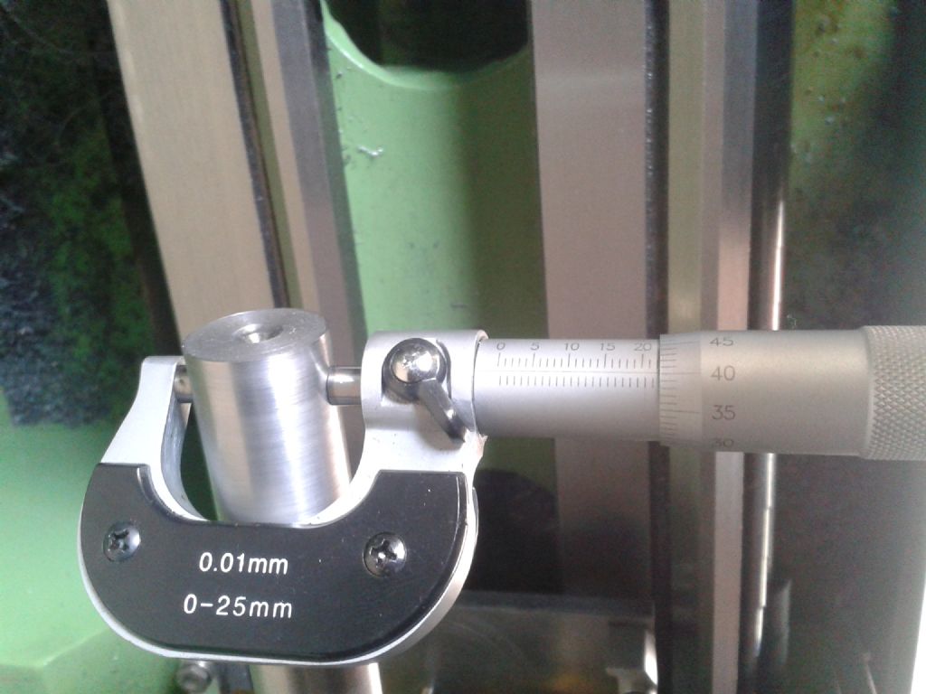
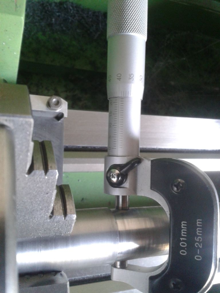
                          The diameter is the same at both ends according to the micrometer, I get what you mean, re dia measuring by dti, as it will follow the taper if there is one.

                          The tool I'm using is HSS one of the ready made ones from chronos, I just rounded off the edge. I checked the headstock with a dti on the spindle nose and face and every thing looks fine.

                          When I turned a couple of inches unsupported it did not chatter at all, only when I put 6" unsupported did it chatter. Probably should have turned a shorter test bar.

                          20171111_121101.jpg

                          20171111_120757.jpg

                          #326664
                          David Standing 1
                          Participant
                            @davidstanding1

                            Chris

                            Not meant to be a criticism, but if that micrometer is sitting there unsupported (even if it is resting on the frame), then you probably have it cranked up way too tight. It is a micrometer, not a G clamp.

                            I can also say, having levelled my machines with a proper Rabone Chesterman machine level, it is astonishing how much a fraction turn of a bed adjusting screw can deflect the bubble.

                            If I wanted an indicative readout from a machine level, I would only use a proper machine level, not a home made one. A normal spirit level won't give the readings you want either, as you have discovered.

                            The fact that you have already detected twist in the bed suggests you should be absolutely sure you have removed all this first, BEFORE attempting any test cutting.


                            Edited By David Standing 1 on 11/11/2017 13:29:00

                            #326668
                            ChrisB
                            Participant
                              @chrisb35596

                              It's ok David, I'm holding it by the ratchet (tried to leave my fingers out of the picture as I didn't do nail polish!) I'm sure it wasn't tight.

                              A proper engineer's level is not an option, don't have one and I'd rather spend the money on other tools which I really need. I one I mocked up is by no means anywhere near a proper level, but it gives a far better picture than a normal level and allows for some adjustment to be made, where as with a normal level I was blind.

                              To be honest I'm pretty much almost satisfied the way it's running now, it's turning a set diameter over a length with no significant taper. The thing which is bothering me is the tailstock deflecting the work when tightening the spindle/barrel lock.

                              Will check the posted links re tailstock alignment and see if it fares a bit better

                              Thanks to all contributors for you help

                              #326676
                              Neil Wyatt
                              Moderator
                                @neilwyatt

                                If you want a 'target' to aim for schlesinger limit for spindle alignment is 0.02mm over 300mm.

                                Tailstocks generally don't stay aligned for a long period of use and should be reset before critical jobs.

                                Neil

                                #326703
                                ChrisB
                                Participant
                                  @chrisb35596

                                  Tried the rollies dad method and managed to get the horizontal alignment right, but vertical alignment was another story. Instructions say to lift both corners either tailstock or headstock side, but which ever side I lift no change occurs, must be doing something wrong.

                                  #326727
                                  peak4
                                  Participant
                                    @peak4

                                    Chris, Firstly I should stress that I'm not a trained engineer, well I am, but in telephony not mechanical. Everything I've learned has been self taught, so read anything I write with an appropriate pinch of salt. wink

                                    I'd suggest that the reason you've struggled with the vertical alignment is to do with rigidity of the workbench and lack of mass in the headstock, plus it would only really work for lathes with 6 or more mounting bolts, 4 at the headstock and 2 at the tailstock on a very rigid bench.
                                    If your lathe is significantly out of vertical alignment, I wonder if having a word with Warco might be a good idea, as that really should be running more or less true when it left their depot. I'm assuming here that the headstock was correctly bolted down when it left the factory, without any flecks of paint underneath (Think Hubble Telescope)

                                    I think you understand the principal of putting a twist in the bed to make it turn parallel with a chuck mounted workpiece. The vertical alignment would require the whole of the bed bending a tiny amount with respect to the centre of rotation of the headstock spindle, and I can't imagine that this should be required in a lathe of this size.

                                    The caveat to that is, have you actually put a bend in the bed whilst adjusting the twist in it. If so, don't worry as I'm sure it will be within the elastic limit of the cast iron. That is, in the ideal world, if all four bolts at the headstock are firmly fastened and cannot move at all in relation to the ground, then everything about the headstock is fixed and all adjustments at the tailstock end are in relation to it.

                                    "Levelling the lathe" (with a capital L) refers not just to getting it level from headstock to tailstock, indeed, that is the least important, though obviously it should be as "level" as possible. The main one is fore and aft, which should be the same at both ends of the bed, hence the "twisting" scenario to make it so.

                                    I think you should be able to see that, if the headstock casting is truly immovable, then if the tailstock bolts were pulling that end into the bench as the wood squashes, the the bed would deflect downwards at that end. Obviously a similar scenario if you put a couple of washers under the tail end of the bed before tightening down the headstock, then the tail end of the bed would deflect upwards, with respect to the headstock.

                                    I'm assuming that since you have neither a calibrated test bar or precision level, you will need to sort it out by turning and measuring.

                                    I'd suggest making sure that in your case the "level" between head and tailstock in neutral, and that any differential shimming only adds a twisting, rather than a bending moment as well, in order to keep the vertical alignment correct.

                                    Here's the way I set up my Myford, which may or may not be approved of by the many apprentice trained engineers on here.

                                    Take a decent length of steel bar, similar to what you've been using and maybe a foot or so long, clean one end and mount in the chuck. thin down the middle section of the bar by a couple of mm or so, similarly the far end as well; no need for accuracy. The intention being, that you well be left with two collars standing proud of the main bar as far apart as the length of bar will allow. (make sure you leave enough room at the right hand end beyond the collar to allow a drive dog to be fitted later.)
                                    Now sharpen and hone a HSS tool to the best edge you can get. Hopefully by now if you've been honing for long enough, the formative test bar will have cooled down, so take the very finest of cuts to both collars.

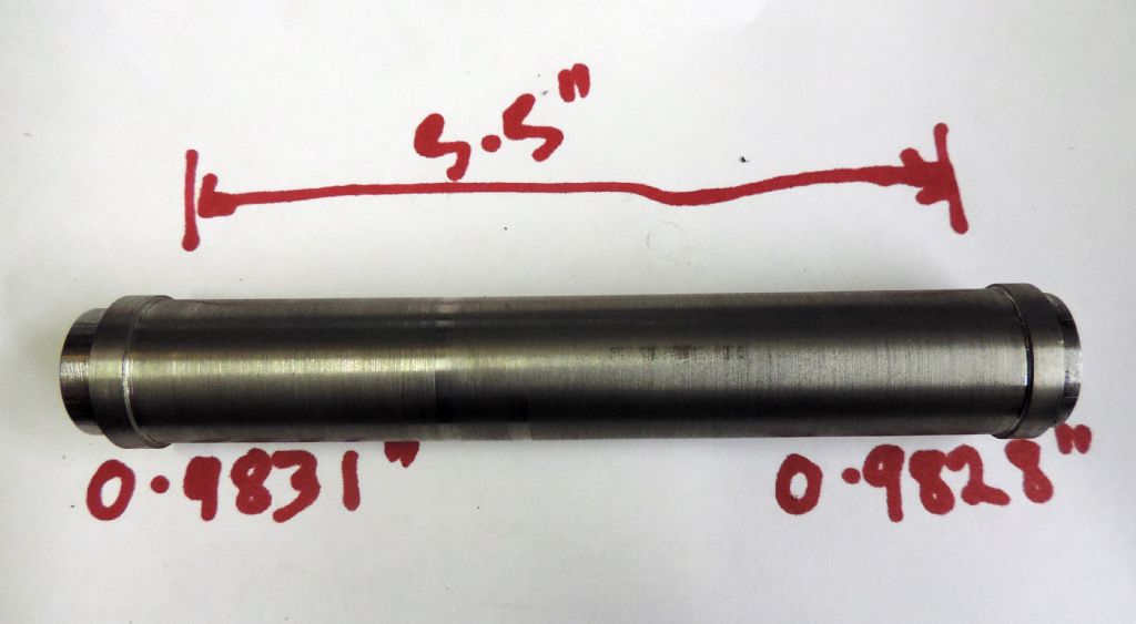
                                    Measure them with a micrometer, ideally a "tenths" one – mine are all imperial. If they aren't exactly the same diameter, which is most likely, this should tell you which way you need to apply a twist to the bed.
                                    Once you've managed to get two identical collars, you know the two ends of the bed are "Level" with each other.

                                    Only now can you turn your attention to the tailstock.

                                    Centre drill both ends of the bar. Either fit, and check, a centre in the headstock taper, or chuck a bit of steel in the 3 jaw and turn a taper on the end to make a centre which you know is true – it must be you've just made it.

                                    Fit a drive dog and turn the bar between centres; with your nice sharp tool, again with the finest of cuts true up and measure the two collars. Keep minimal projection on the tailstock barrel during the operation.This will tell you whether the tailstock needs to move towards or away from the front of the lathe.

                                    Once you have the tailstock correct, true up the end of the bar that you held in the chuck prevously, as it will now be slightly out compared to the centre drillings.

                                    You now have a lathe that's reasonably well set up, and a re-useable test bar as well, so keep it in a padded box with some rust resistant paper. OK so it's not as good as a calibrated precision ground bar, but if you could afford one, you'd have already bought it. smiley

                                    Bill

                                    Part 2 to follow

                                    #326728
                                    peak4
                                    Participant
                                      @peak4

                                      Part 2


                                      You can use the bar between centres with a dial gauge on the saddle, whenever you have need to offset the tailstock in the future and want to return it to the correct alignment.

                                      If you have a boring head consider making a centre to fit one of the holes in it, put the boring head in the tailstock and use the diameter screw of the boring head to offset the home made centre; that way tyou don't need to disturb the tailstock offset, and you have a nice screw adjustment to set the amount of taper you're turning.

                                      Also, now you've made the test bar, set up a DTI on the bed/saddle running on the right hand collar. Slacken the tailstock bed clamp, and the barrel clamp slightly and wind out the tailstock barrel, pushing the tailstock casting itself off to the right hand end. If you observe the DTI whilst winding the handle, is should give you an idea if the tailstock barrel is projecting in line with the bed.


                                      In some ways, the Myford setup is slightly easier as there are only 4 bolts, so there is less chance of "bending" the bed.
                                      Also the mounting bolts are able to "push" as well as "pull" with respect to the lathe cabinet/workbench. 
                                      There's a hollow bolt under the bed which runs in a threadded hole in the cabinet raising block.

                                      Passing through the lathe foot is a thinner stud which goes though the afore mentioned hollow bolt and is retained in the cabinet.
                                      This means that you can impart a true twist, without pulling the tailstock end of the bed downwards.

                                      I hope this reads OK as I've not had time to proof read it as dinner's ready.

                                      Good luck

                                      Bill

                                      p.s. there is an argument which suggests that the test bar should be a thick walled pipe, as it would deflect less under its own weight, but I can't imagine it would make much difference in the sizes of our "hobby" lathes, and also you would lose the advantage of being able to use it between centres to set the tailstock.

                                      Edited By peak4 on 11/11/2017 23:03:04

                                      Edited By peak4 on 11/11/2017 23:03:49

                                      #326734
                                      Anonymous

                                        I suspect the change of alignment when the tailstock barrel is locked is down to the locking mechanism. A simple clamp on the barrel will inevitably move it slightly when tightened. Larger industrial lathes sometimes use two curved pads opposing each other so, in theory, the barrel doesn't move when clamped.

                                        Andrew

                                        #326736
                                        Neil Wyatt
                                        Moderator
                                          @neilwyatt

                                          If you skim the two collars at the same setting, but reversing the bar between the two skims) you can get them very close in size. I take the 0.0003" difference with a pinch of salt as I don't believe I can really measure to a tenth whatever my micrometer claims:

                                          test bar.jpg

                                          #326737
                                          not done it yet
                                          Participant
                                            @notdoneityet

                                            If you have a boring head ….

                                            Simple little gems like that make rreading these posts worthwhile! Locked safely away until needed – unless I forget it!

                                            #326745
                                            Michael Gilligan
                                            Participant
                                              @michaelgilligan61133
                                              Posted by peak4 on 11/11/2017 22:48:58:

                                              p.s. there is an argument which suggests that the test bar should be a thick walled pipe, as it would deflect less under its own weight …

                                              .

                                              Schlesinger describes such a bar, in some detail … The bore is done in several stepped diameters [to approximate a taper]. But I agree it's probably only relevant to the acceptance testing of toolroom-class lathes.

                                              MichaelG.

                                              .

                                              P.S. He does mention that "Deflections caused by the spring pressure of the dial-gauge plunger are negligible if this pressure is less than 3 1/2 ounces."

                                              … Which I find quite reassuring.

                                              Edited By Michael Gilligan on 11/11/2017 23:56:37

                                              #326749
                                              peak4
                                              Participant
                                                @peak4
                                                Posted by Neil Wyatt on 11/11/2017 23:07:30:

                                                If you skim the two collars at the same setting, but reversing the bar between the two skims) you can get them very close in size. I take the 0.0003" difference with a pinch of salt as I don't believe I can really measure to a tenth whatever my micrometer claims:

                                                test bar.jpg

                                                That's pretty much what I was describing Neil, but with a longer projection on the left hand end, so it can be held in a chuck for the initial setup of any required twist in the bed.
                                                Unfortunately I lost mine due to a shed roof leakage and a subsequent attack of tinworm.

                                                Since then I've found a 2 morse extension bar, but unlike most seen on the net these days, it is nicely ground all over. Ex military from Anchor Surplus in Nottingham years ago.
                                                I now use this as a test bar from the headstock spindle taper, and for between centres use, add a blank stub arbour to the female end. Again not up to calibrated test bar standards, but adequate for my use.

                                                I can get more "tenths" DTI deflection by gently leaning on the lathe than the bodged "test bar" idnicates.
                                                Our lathes normally just ain't that rigid unless you are fortunate to have a high quality toolroom machine.

                                                #326750
                                                peak4
                                                Participant
                                                  @peak4
                                                  Posted by not done it yet on 11/11/2017 23:14:27:

                                                  If you have a boring head ….

                                                  Simple little gems like that make rreading these posts worthwhile! Locked safely away until needed – unless I forget it!


                                                  I originally thought I'd come up with something novel, then subsequently read that it's been a dodge for donkey's years.

                                                  For the home made centre in mine, I used an old broken solid carbide centre drill., fitted to a mild steel sleeve to take it up to 1/2" to fit the hole in the boring head.
                                                  Obviously not the easiest stuff to re-profile, but since no-one told be how I should do it, I came up with yet another bodge.

                                                  The Clarkson T&C Grinder was near the lathe, and I have a flexible drive shaft with a drill chuck on the end.
                                                  Another drill chuck on a spindle was secured to the bed of the Clarkson and the broken centre drill chucked up in it. Drive for the nescent centre was provided by the flexible polishing arbour, itself driven by the Myford behind me. Hardly conventional I assume, but did the job nicely. Yes I did cover the lathe bed with paper towels first.

                                                  Bill

                                                  Edited By peak4 on 12/11/2017 00:22:16

                                                  #326761
                                                  ChrisB
                                                  Participant
                                                    @chrisb35596

                                                    Thanks Bill for the detailed explanation, the Wm280 comes with 6 mounting bolts, 4 on the H/S side 2 on the T/S, will give it another go this morning…thinking about it, I used a 12mm "precision" steel bar which was fairly long, dont recall how much it extended out of the chuck, but must have been 500mm or so. Could it have slightly bowed under its weight?

                                                    #326780
                                                    peak4
                                                    Participant
                                                      @peak4
                                                      Posted by ChrisB on 12/11/2017 07:05:07:

                                                      Thanks Bill for the detailed explanation, the Wm280 comes with 6 mounting bolts, 4 on the H/S side 2 on the T/S, will give it another go this morning…thinking about it, I used a 12mm "precision" steel bar which was fairly long, dont recall how much it extended out of the chuck, but must have been 500mm or so. Could it have slightly bowed under its weight?

                                                      I've not done any calculations but at only 12mm, I'd have thought it would sag a little bit, plus a bit more due to the pressure of the DTI tip.

                                                      With 4 mounting bolts on the headstock, I'd have thought it possible to fix it down pretty rigidly, such that the two at the tailstock end could drag that end down a bit with respect to the, now rigidly mounted, headstock.

                                                    Viewing 25 posts - 26 through 50 (of 55 total)
                                                    • Please log in to reply to this topic. Registering is free and easy using the links on the menu at the top of this page.

                                                    Advert

                                                    Latest Replies

                                                    Home Forums Beginners questions Topics

                                                    Viewing 25 topics - 1 through 25 (of 25 total)
                                                    Viewing 25 topics - 1 through 25 (of 25 total)

                                                    View full reply list.

                                                    Advert

                                                    Newsletter Sign-up