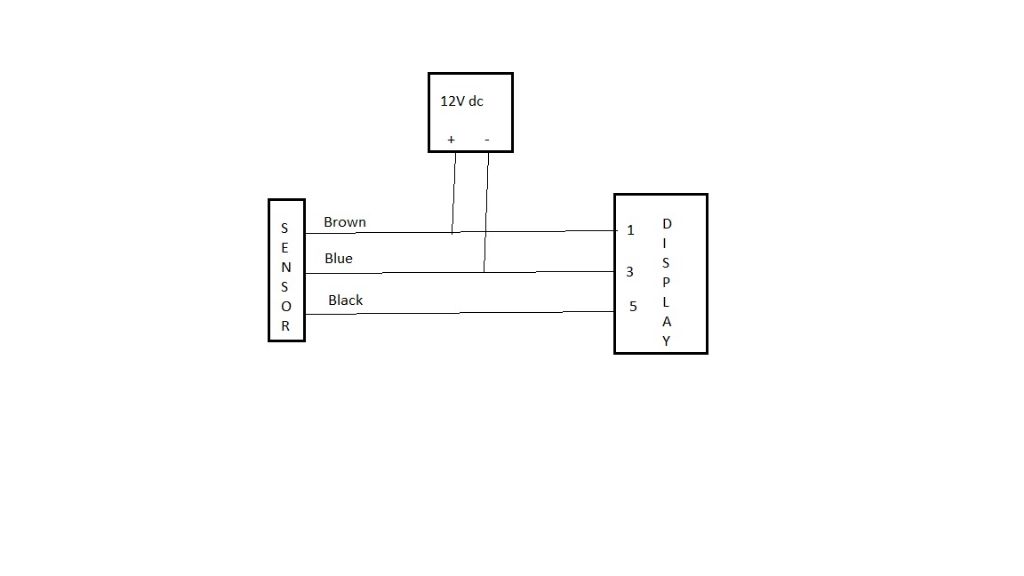
Hello Everyone,
I have one of those very cheap digital rpm displays from China. Mine is the blue four digit display.
I have read various threads on this forum, watched a number of you-tube videos and searched other web sources for information. I believe I have connected it the way the majority of opinion leads me to believe is correct.

The 12v power supply is from a wall wart. When connected as shown the display shows 0000. The light on the rear of the sensor is illuminated.
For testing I have the magnet (neodymium) fixed to my Fobco drill chuck controlled by a VFD and the sensor is aligned temporarily in a small vice on the drill table. When I rotate the chuck nothing changes! The display stays at 0000 regardless of speed.
Yes I have changed the magnet over and that made no difference. I clearly have power to both the display and sensor so can someone please tell me the blindingly obvious! What have I done wrong?
By the way the lead from the display is a five core ribbon cable, no distinguishing colours and I have assumed they are numbered left to right whilst looking at the rear of the display. If I connect it right to left the display is blank.
Just to confuse mere mortals like me on one of the suppliers listing it says:
1 Power source + (assume this is dc supply +)
2 Power ground (assume this is dc supply -)
3 Signal earth (assume sensor but which lead?)
4 Empty (understood!)
5 Measuring + (assume sensor but again which lead?)
Another supplier lists the sensor connections as:
Brown (Power +)
Black (Test +)
Blue (Signal)
Any ideas welcome please.
Tim Stevens.


