Determining/measuring sub-micron displacement

Advert

Determining/measuring sub-micron displacement

Home Forums Help and Assistance! (Offered or Wanted) Determining/measuring sub-micron displacement

Viewing 21 posts - 26 through 46 (of 46 total)
  • Author
    Posts
  • #592530
    Jouke van der Veen
    Participant
      @joukevanderveen72935

      Without deep thinking:

      Submicron displacements to be measured by means of Michelson interferometry?

      And that with monochromatic light (laser)?

      Is this a variant of or improvement of the Foucault measurement mentioned earlier?

      Jouke

      Edited By Jouke van der Veen on 02/04/2022 10:58:26

      Advert
      #592531
      Graham Meek
      Participant
        @grahammeek88282

        Hi Joe,

        I have been giving this some thought and think that a horizontal lever which is suspended vertically preferably by a thread. At one end mount a small mirror at an angle. Have a fixed stop for the lever to butt up against when at rest. Shine a Laser pen at the mirror and have the spot somewhere convenient on the workshop wall.

        If you move your probe into contact with the lever and mark the dot on the wall. Move away to break the contact and mark the dot again. the difference should be simple trig to sort out.

        We used to use a similar technique when setting up the lasers on the Radiotherapy treatment machines.

        Regards

        Gray,

        #592544
        KWIL
        Participant
          @kwil

          Laser spots are a always too fuzzy for me. What is the error size when deciding where the centre actually is?

          How does this compare to Joe's desire for finite small measurements?

          #592552
          Michael Gilligan
          Participant
            @michaelgilligan61133

            I must confess utter bewilderment at the devious complexities being suggested

            My microscope stand provides an entirely mechanical solution to Joe’s problem [just think of it as a big, sensitive, micrometer] … Joe’s device identifies contact [ that’s what it’s for ! ], so the exercise is simply one of measuring the mechanical hysteresis of the device, to a few tenths of a micron.

            Why is everyone making it so complicated ?

            dont know MichaelG.

            #592555
            SillyOldDuffer
            Moderator
              @sillyoldduffer

              Posted by Michael Gilligan on 02/04/2022 13:11:39:

              Why is everyone making it so complicated ?

              dont know MichaelG.

              Joe is in Namibia?

              Why is nothing ever easy?

              sad

              Dave

              #592563
              Michael Gilligan
              Participant
                @michaelgilligan61133

                Yes I know Joe is in Namibia, Dave

                But that’s no justification for over-complicating the solution with smoke and mirrors

                Joe could surely make something which approximates the basic mechanics of the Leitz focusing mechanism.

                MichaelG.

                #592682
                Graham Meek
                Participant
                  @grahammeek88282

                  Clearly my simple solution has upset a few.

                  The principle is based on the Galvanometers used in my College days.

                  Above all, there is no need to manufacture anything to achieve a fairly accurate result, the materials would I suspect be readily to hand.

                  Silly me, I thought this was the purpose of the post.

                  Regards

                  Gray,

                  #592696
                  Michael Gilligan
                  Participant
                    @michaelgilligan61133
                    Posted by Graham Meek on 03/04/2022 10:54:38:

                    Clearly my simple solution has upset a few.

                    .

                    Good afternoon, Gray

                    If by a"a few" you mean me … Then no, it hasn't

                    Sorry if it appeared otherwise.

                    .

                    If I am upset by anything, it is the fact that most of the respondents appear to think that this is a difficult problem.

                    You and I both know that magnification of the movement is all that's required.

                    I suggested doing it at input / you suggested doing it at output.

                    The underlying concept is essentially the same.

                    MichaelG.

                    #592717
                    Joseph Noci 1
                    Participant
                      @josephnoci1

                      Chaps, it was not my intention to stir the pot so badly…I am certainly not upset with anyone here!

                      Perhaps I do share some of the blame however- I indicated I am trying to measure the displacement, when I suppose what is really needed is to find a way to show that the detection 'accuracy' is 'good enough' to within limits so small that the actual value of the deflection does not matter. In other words, for a edge detection probe, one would probably be safe to assume a deflection of less than 0.01mm is acceptable, since we rarely work to better than that anyway. But if I can achieve better than 0.005mm, then that would be really good. If the actual value lies somewhere between 0.001mm and 0.008mm, it is still really good, but not definitive – but perhaps that does not matter to be able to use the probe definitively.

                      So my absolute requirement statement was poorly put and I apologise..

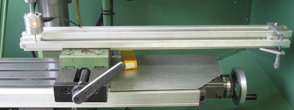
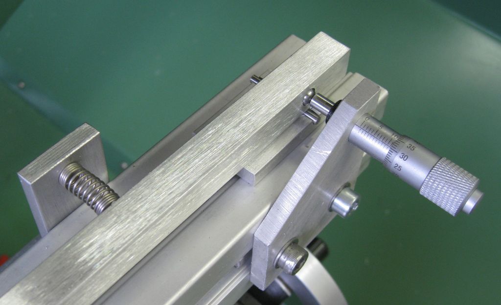
                      That said, I went and made a mechanical 'magnifier' – a long arm, pivot one end, micrometer at 600mm from the pivot, and my probe at 30mm from the pivot, so a 1:20 reduction of Micrometer anvil motion. This is not perfect of course, working in an arc, etc, so the linear movement at 30 mm is not true….but its good enough!

                      Set up in the mill and tested with a 0.01mm indicator, and then a 0.001mm indicator ( of dubious nature..)

                      Then I set the probe in the mill and tested that for contact – I do believe my contact displacement is less than 0.0005mm, maybe even 0.0002mm…Judge for yourselves..

                      The device in the mill, turned 90deg to check Z axis of the probe:

                      multiplier overview - z.jpg

                      Mic end:mic end.jpg

                      Pivot end:

                      pivot end.jpg

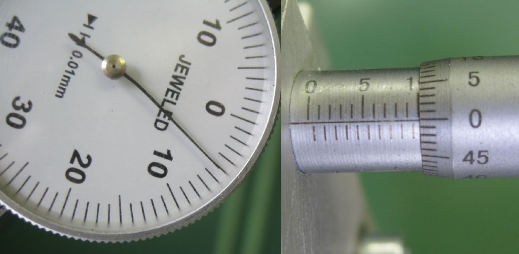
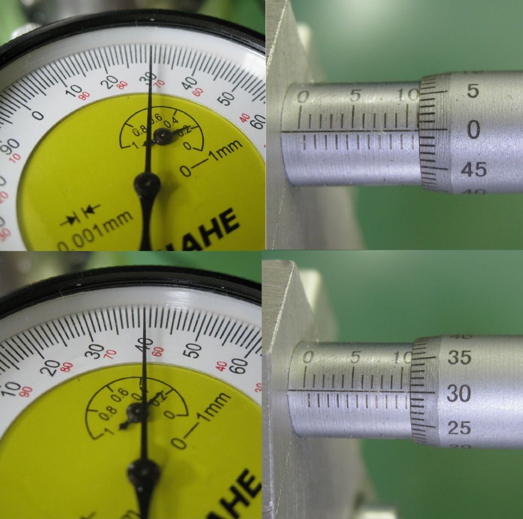
                      Using a 0.01mm indicator-below: (note, arm multiplier = 20)

                      Fist row – Dial and Mic at Zero.

                      Second row – Mic plus 5div x 0.01mm = 0.05mm div 20 = 0.0025mm at indicator

                      Third row – Mic 25 divisions = 25 x 0.01mm = 0.25mm div 20 = 0.0125mm at indicator.

                      Dial appears to be under-indicating by 0.002mm maybe?

                      mic_to_0.25mm.jpg

                      Mic moved in 1mm, div 20 = 0.05mm, Dial shows 0.05mm – correlates OK.

                      mic_0.5mm.jpg

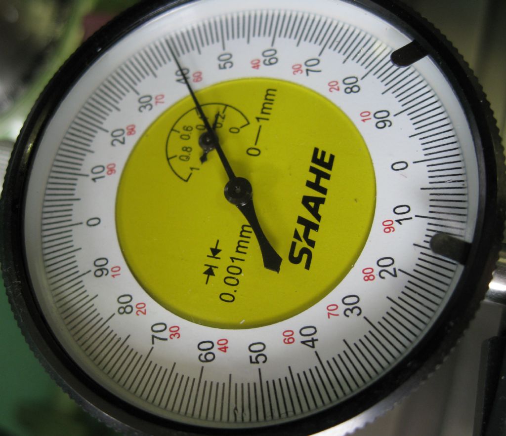
                      Now using a dubious 0.001mm indicator:

                      0.001mm dial.jpg

                      First row – Dial 'zeroed' at 30, Mic zeroed at 11mm,

                      Second row – Mic moved plus 20div = 20 x 0.01mm = 0.2mm div 20 = 0.01mm

                      Dial moves from 30 to 40 = 10 div x 0.001mm = 0.01mm – correlates with Micrometer.

                      mic to 0.2mm.jpg

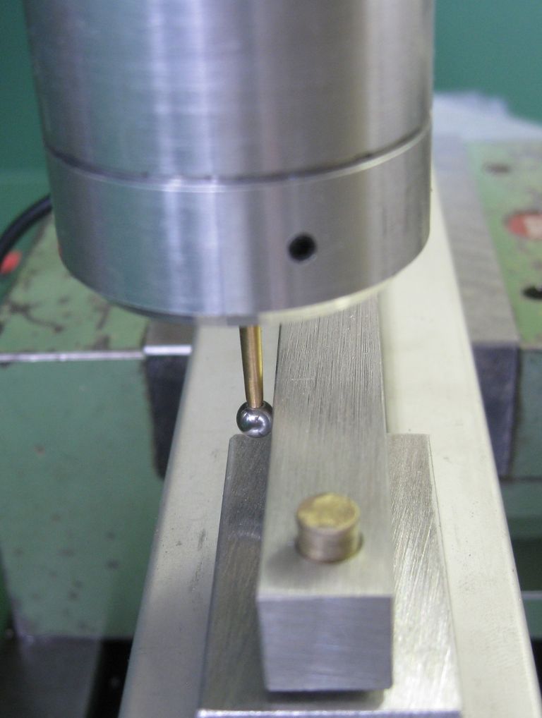
                      Then fitted the probe – see contact point with lever in photo below.

                      probe in x.jpg

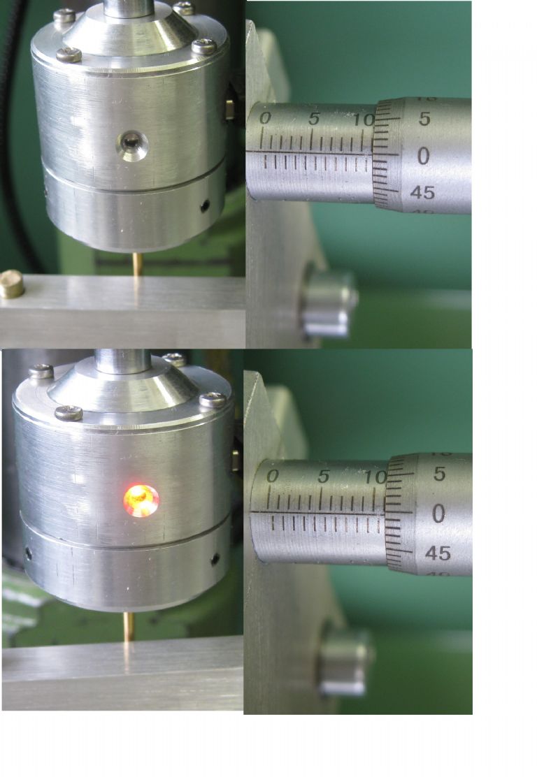
                      Photo below shows probe OFF, Mic = 0

                      Second row shows probe on – contact made, Mic = 1/2div (maybe?) = 0.01 / 2 =0.005mm

                      0.005mm / 20 ( lever multiplier) = 0.00025mm movement at probe tip…Believe it or not!

                      probe in x on_off.jpg

                      Similar tests were done in the Z plane with the test lever on its side – similar results obtained!

                      #592721
                      Michael Gilligan
                      Participant
                        @michaelgilligan61133

                        yes

                        #592722
                        Michael Gilligan
                        Participant
                          @michaelgilligan61133

                          .

                          Edited By Michael Gilligan on 03/04/2022 15:21:27

                          #592723
                          Michael Gilligan
                          Participant
                            @michaelgilligan61133

                            .

                            Edited By Michael Gilligan on 03/04/2022 15:20:56

                            #592724
                            Michael Gilligan
                            Participant
                              @michaelgilligan61133

                              Oops … Typing on the phone blush

                              Edited By Michael Gilligan on 03/04/2022 15:24:02

                              #592782
                              Jouke van der Veen
                              Participant
                                @joukevanderveen72935

                                Joe,

                                I somewhere read in your topic that you found that the ball is oscillating in a more or less spherical motion. You already used a laser interferometer for that. So forget about my Michelson interferometer.

                                But I have a question. Could it be that stopping the ball from its “random” spherical oscillation needs more displacement (harder contact) than to start the ball oscillate again in a different mode when loosing contact? But then contact position should change by repeating touches, or not?

                                Jouke

                                #592786
                                John Haine
                                Participant
                                  @johnhaine32865

                                  Sounds like you have cracked the measurement problem Joe. A very interesting design, how do you cope with over travel? The original Renishaw tri-bar design is pretty robust, but am I right that the probe is solidly attached to the piezo disc?

                                  #592790
                                  Joseph Noci 1
                                  Participant
                                    @josephnoci1
                                    Posted by Jouke van der Veen on 03/04/2022 20:48:53:

                                    Joe,

                                    I somewhere read in your topic that you found that the ball is oscillating in a more or less spherical motion. You already used a laser interferometer for that. So forget about my Michelson interferometer.

                                    But I have a question. Could it be that stopping the ball from its “random” spherical oscillation needs more displacement (harder contact) than to start the ball oscillate again in a different mode when loosing contact? But then contact position should change by repeating touches, or not?

                                    Jouke

                                    Hi Jouke,

                                    Yes, I had access to the interferometer lab for those measurements, but the test lab setup is for very small objects and to build some mechanism to do the deflection measurment in a manner that is cold fit into their chamber was a bit of an issue, and the Lab manager got cold feet…

                                    I was also wondering about possible hysteresis in the contact/break contact process, but in the tests I did with the lever arm above I did 20 repetitions in the horizontal plane, and redid them with the probe rotated 90deg about its vertical axis – The delta was lost in the noise around the 0.0002mm region, which is so small that I called the deflection to be 0.005mm or better and left it at that!

                                    #592791
                                    Joseph Noci 1
                                    Participant
                                      @josephnoci1
                                      Posted by John Haine on 03/04/2022 21:14:38:

                                      Sounds like you have cracked the measurement problem Joe. A very interesting design, how do you cope with over travel? The original Renishaw tri-bar design is pretty robust, but am I right that the probe is solidly attached to the piezo disc?

                                      Hi John,

                                      Yes, the probe is soldered to the disc – with a flat 'foot' so the disc must give..

                                      Over travel is a problem on this setup. more than 1mm in horizontal will pop the disc from its tri-point holder. – open up, refit the disc, and reset runout!

                                      Over travel of 1mm in Z will probably break the piezo disc. Can be avoided in a CNC machine if probing is auto and sensible probing speeds are used, but crashes are inevitable.

                                      I am looking to spring mount the disc tri-point support ring to the runout setting mechanism so that it can 'spring' away- supported on three pointed pins in three mating holes with the cones on the hole periphery – hard to describe, but will self centre and have a 'hard' location, with the three pins on a ring that moves laterally to set runout. Photo's when I have done it…

                                      #592820
                                      John Haine
                                      Participant
                                        @johnhaine32865

                                        Could be worth looking at the various Renishaw patents to see how they solved this problem. (I assume that you don't intend to make and sell these probes!)

                                        I'm inspired by your work to evaluate my own electrical contact-sensing probes.

                                        #592822
                                        Howard Lewis
                                        Participant
                                          @howardlewis46836

                                          The advantage of using a mirror to show the deflection is that a light beam has no easily measurable weight or inertia. And can be made as long as is practicable, to maximise resolution..

                                          Hence use in mirror galvanometers

                                          Howard

                                          #592829
                                          Kiwi Bloke
                                          Participant
                                            @kiwibloke62605

                                            I hesitate to add more ramblings to this thread, and lower its signal-to-noise ratio. I tend to post late in the evening, after good food and drink – not the best recipe for clear thought. I'm afraid I've muddied the waters by my last post – it's largely based on a false assumption about how this probe works.

                                            Joe, I'll PM you.

                                            #593072
                                            Joseph Noci 1
                                            Participant
                                              @josephnoci1

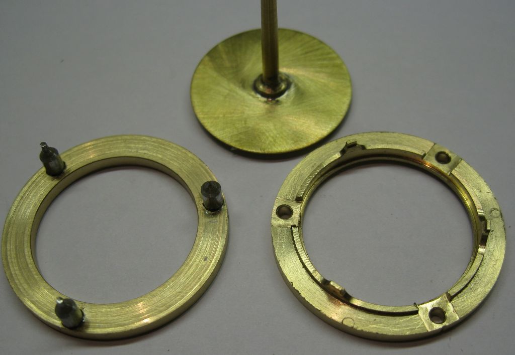
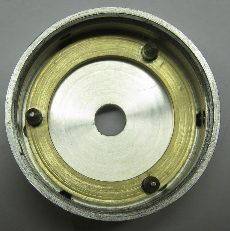
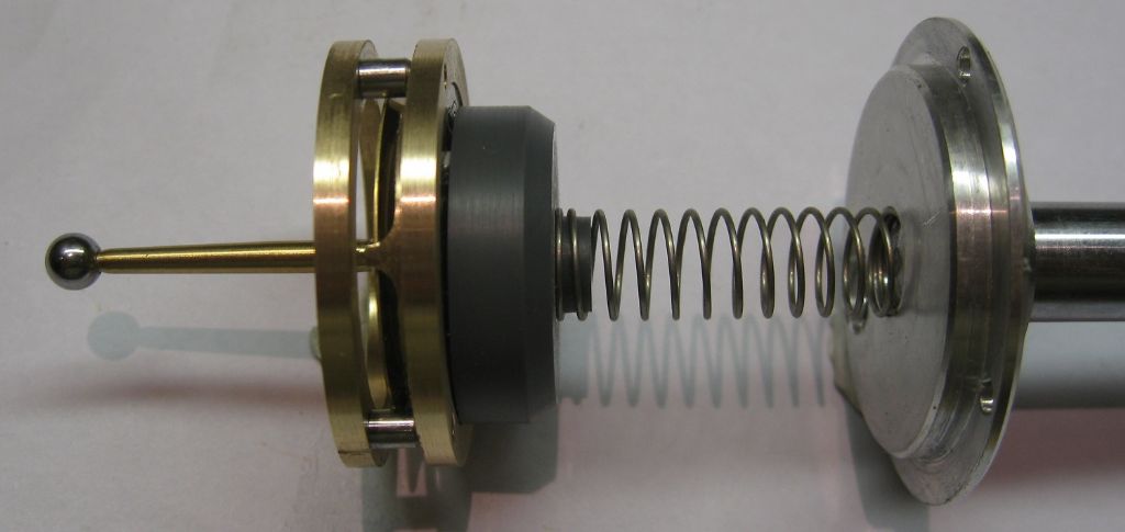
                                              I have 'improved' the probe tip allowed displacement before damage. A ring that is used to centre the probe tip is now fitted with three hard pins, ground conically, the cone resting in three bevelled holes in the tri-support disc holding the piezo element.

                                              Two of the pins have extensions into the mating hole so that large ball displasements do not knock the ring of the pins.

                                              rings apart.jpg

                                              ring_probs assy.jpg

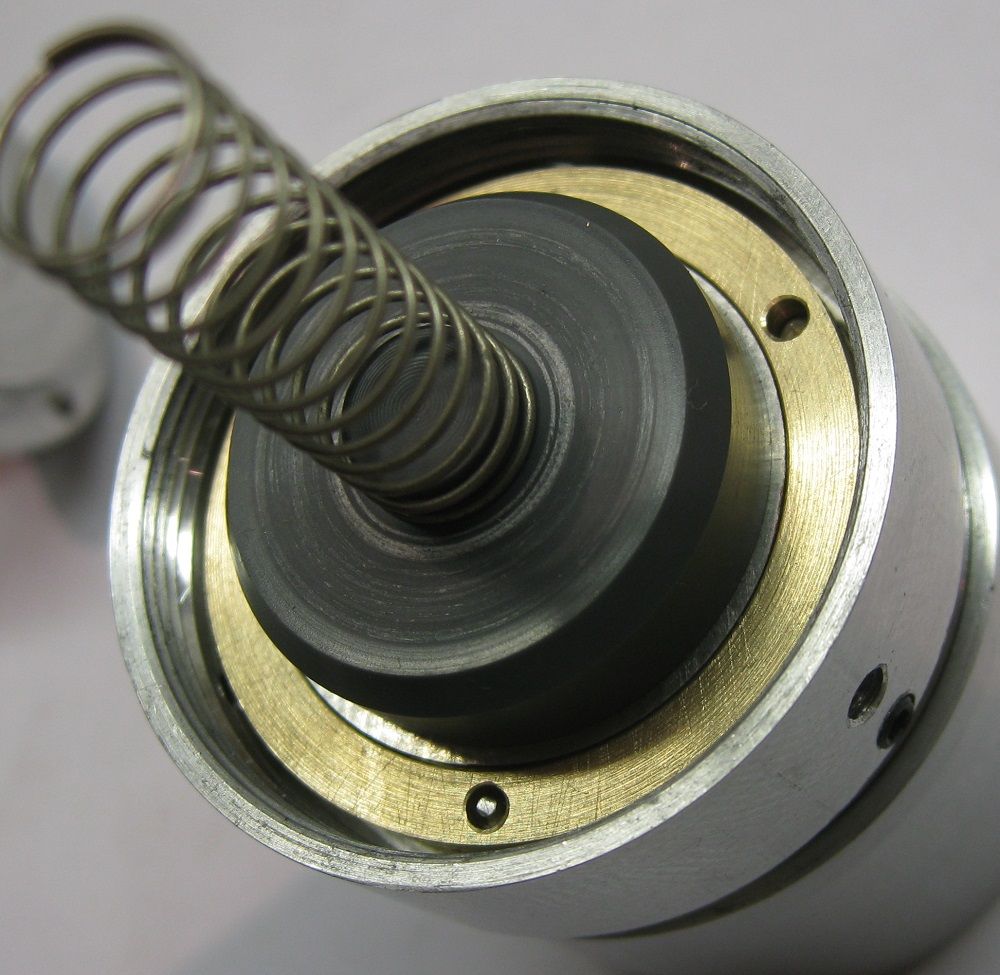
                                              The pin ring fitted into the head, held by the three runout grubscrews.

                                              pin ring in head.jpg

                                              The spring assembly that makes it all work..

                                              assy1.jpg

                                              pin ring assy.jpg

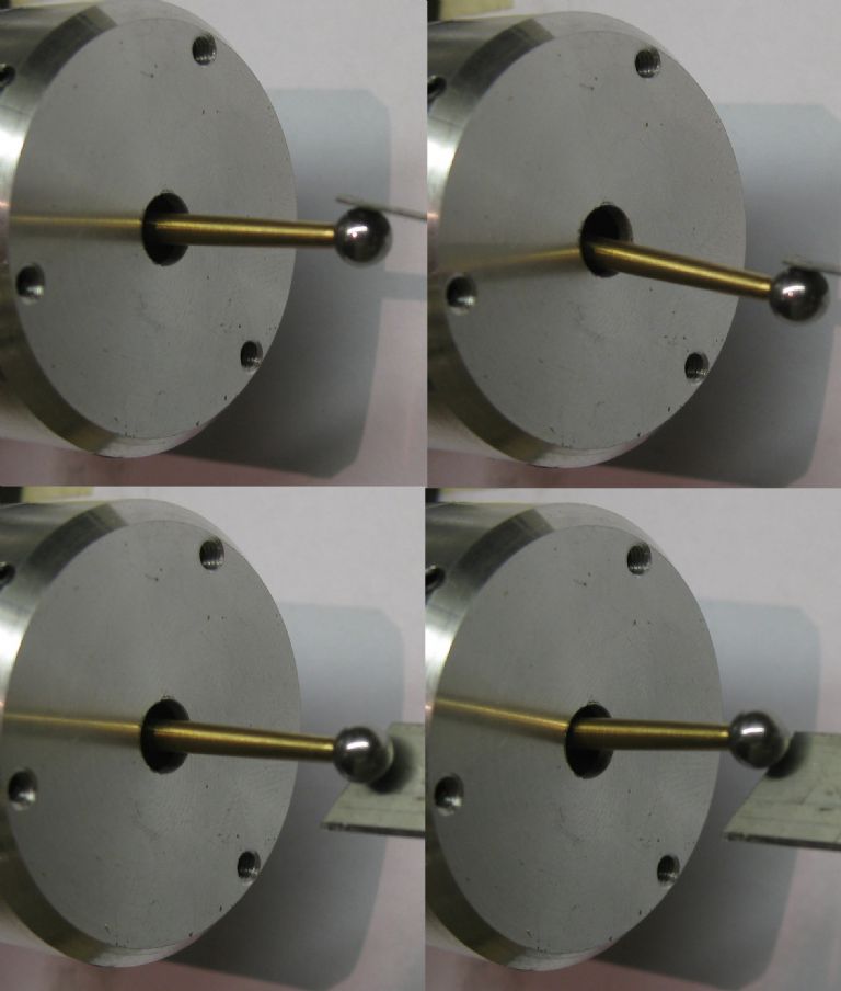
                                              View of the motion when the ball is displaced

                                              probe motion.jpg

                                              probe displacements.jpg

                                              The setup seems to work well – with it set up in the mill with the magnifier arm I still get the same results as before for contact detection displacement ( very, very small..) and when I jiggle the ball around , apply excessive displacement ( 4mm approx) the ball seems to return to the same place, within the small dimensions measured by my magnifier arm – 'resetability' seems to be very good.

                                              Now what to do with the thing…

                                            Viewing 21 posts - 26 through 46 (of 46 total)
                                            • Please log in to reply to this topic. Registering is free and easy using the links on the menu at the top of this page.

                                            Advert

                                            Latest Replies

                                            Viewing 25 topics - 1 through 25 (of 25 total)
                                            Viewing 25 topics - 1 through 25 (of 25 total)

                                            View full reply list.

                                            Advert

                                            Newsletter Sign-up