Chester Super Lux – Motor Failure

Advert

Chester Super Lux – Motor Failure

Home Forums Manual machine tools Chester Super Lux – Motor Failure

Viewing 25 posts - 26 through 50 (of 50 total)
  • Author
    Posts
  • #384911
    Colin Heseltine
    Participant
      @colinheseltine48622

      SOD

      I had got the capacitor disconnected at one end, so I had one probe pushed hard onto the fixed connection and the other end wedged to hold tight on the termination ring on the second capacitor lead. Not the easiest of positions to work in, stood on a chair leaning on top of gear head to steady oneself.

      Colin

      Advert
      #384916
      Les Jones 1
      Participant
        @lesjones1

        The capacitor should still be connected. It is realy the top two terminals that you are shorting out. You could just connect a piece of wire between the terminals so you have your hands free to hold the meter probes. I did not know that chester had a site at burtonwood. I have been to the Warco site a Burtonwood when I was deciding which lathe to buy but it was only a showroom and it was opened up by a none technical person from the office. I have not even seen the Super lux mill let alone taken the motor appart. I don't think Chester would even stock spare capacitors at their Hawarden site.

        Edit, I should have worded my instructions more clearly yesterday. I should have said short the top two terminals in the motor connecton box that the capacitor is connected to together.

        Les.

        Edited By Les Jones 1 on 10/12/2018 18:25:46

        Edited By Les Jones 1 on 10/12/2018 18:31:48

        #384922
        Colin Heseltine
        Participant
          @colinheseltine48622

          Les,

          Burntwood Staffordshire.

          Step 2 was done with probes on V1 and W2 and then with capacitor connected the capacitor terminals were shorted.

          This gave the display as shown in earlier picture. U1 and U2 were still disconnected is this correct?

          I only had the capacitor disconnected when checked its capacitance with the meter.

          Colin

          #384934
          Les Jones 1
          Participant
            @lesjones1

            I should read posts properly. It looks like the centrifugal switch is faulty. U1 and U2 are the run winding and I asked for them to be disconnected to avoid that winding being connected to the start winding connections via the reversing switch and causing false readings. If it was me I would confirm that if two 100 watt. (40 to 150 watt would do.) were connected one to the wires U1 and U2 and the other to V1 and W2 (With those wires disconnected from the motor.) that they lit up when the start button was pressed as if starting the motor in both directions of the forward reverse switch. That would prove that power would be getting to both windings of the motor. I would do that before trying to dismantle the motor to get at the centrifugal switch. When I misread your locations as near Burtonwood I thought I would probably be close enough to you to look at the problem myself as a last resort.

            Les.

            #384941
            FMES
            Participant
              @fmes

              Do these motors actually have a centrifugal switch? Only my Fobco drill has a motor that you can actually hear the switch cutting back in on the rundown.

              Both Warco Lathes and Mill do not, neither did my SIP compressor – all had two capacitors.

              Fortunately when my mill packed up in the way described above it was obvious to see by the damaged capacitor casing.

              Simply replacing it cured the problem

              #384960
              Colin Heseltine
              Participant
                @colinheseltine48622

                Les,

                To make sure I understand. The bulbs should be connected to the wires that I have disconnected from the connection block on the motor?

                Colin

                PS Many Thanks for your assistance with this.

                #384965
                Les Jones 1
                Participant
                  @lesjones1

                  Yes, One bulb to U1 and U2. The other bulb to V1 and W2.

                  Les.

                  #385022
                  Colin Heseltine
                  Participant
                    @colinheseltine48622

                    Les,

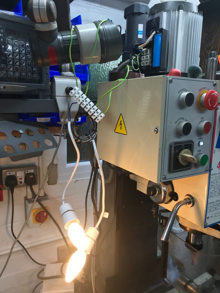
                    Both bulbs power up

                    img_4321.jpg

                    Is the final concensus that it is the centrifugal switch that is faulty even though the capacitor gives odd readings.

                    Colin

                    #385044
                    John Rudd
                    Participant
                      @johnrudd16576

                      I'd say the start cap is open circuit or at least low in value and needs replacing, then the cs needs looking at and maybe require the contacts cleaning or maybe its stuck open…motor strip down time…

                      #385048
                      Les Jones 1
                      Participant
                        @lesjones1

                        Hi Colin,
                        You have now confirmed thet the fault is in the motor. While you have the lamps connected up connect the start capacitor in series with one of them. (As I suggested in my post on 25 Nov at 20:01.) The lamp it is connected in series with should light at almost full brightness as a 150 uF capacitor has a reactance of about 20 ohms at 50 hz. If the lamp lights at near full brightness than the capacitor is probably OK. This is the only way I can suggest testing it without test equipment. From yesterdays tests I am allmost certain that the centrifugal switch is faulty.

                        Les.

                        #385052
                        Colin Heseltine
                        Participant
                          @colinheseltine48622

                          Just connected up with capacitor in circuit with V1 and W2 and both bulbs equal brightness.

                          Will now try and take the back of the motor to get to centrifugal switch. Hopefully the back end platewill remove without me having to unbolt the motor of the geared head as I have no idea how it is connected internally.

                          Colin

                          #385054
                          Stuart Smith 5
                          Participant
                            @stuartsmith5

                            Just a comment about your mains supply voltage and the capacitor rating.

                            The mains voltage can be up to 253 volts in the U.K. and as you are near your local substation, it is to be expected that your supply voltage will regularly be around 245 to 250 volts, and up to 253 volts at periods of light load on the system generally.

                            As long as the capacitor is rated at 250v AC then this will be ok and is what you would expect the rating for a UK machine.

                            #385055
                            Colin Heseltine
                            Participant
                              @colinheseltine48622

                              Rear End Casing removed. No centrifugal switch??

                              img_4326.jpg

                              Where now:?

                              Colin

                              #385061
                              roy entwistle
                              Participant
                                @royentwistle24699

                                Its probably at the other end as there doesn't appear to be any leads at the end shown

                                Roy

                                #385064
                                Les Jones 1
                                Participant
                                  @lesjones1

                                  You will probably have to remove the motor from the mill to get to the screws that bolt the bottom end plate to the casing.

                                  Les.

                                  #385066
                                  Colin Heseltine
                                  Participant
                                    @colinheseltine48622

                                    Oh well. Had a horrible feeling that might be the case. Not sure how the motor shaft integrates into the gearbox. Whether it is splined/keyed onto a gear fixed in gearbox or whether it has a fixed gear on the motor spindle. Will take photos for future reference.

                                    Colin

                                    #385067
                                    Les Jones 1
                                    Participant
                                      @lesjones1

                                      Hi Colin,
                                      The manual I got with my Chester DB-10G lathe contained some drwings of the construction of the lathe. You may be able to get Chester to email you a manual for your mill in .pdf format.

                                      Les.

                                      #385070
                                      Colin Heseltine
                                      Participant
                                        @colinheseltine48622

                                        I have removed the 4 cap head bolts holding motor to the head/gear casing. The motor and base plate will spin round but I do not have the strength to lift it up. The flange is completely flat against the head and cannot get a screwdriver in to ease it up and out.

                                        Any ideas, I do not want to break a lug of the flange.

                                        I will put up another post re removal of motor to see if it triggers any responses.

                                        Colin

                                        #385104
                                        david homer
                                        Participant
                                          @davidhomer12226

                                          Hi Colin

                                          I have a Chester Super Lux bought in 2005, checked today and when i switch it off you can hear the centrifugal switch operate. The motor on mine just slots into a coupling with a nylon key, no other fixings except 4 cap heads through the motor flange.

                                          #385155
                                          Colin Heseltine
                                          Participant
                                            @colinheseltine48622

                                            David,

                                            How did you lift the motor out. I am struggling to grip it. I can lift it about 20thou using a screwdriver under the fixing lug and located into one of the fixing bolt holes for the gearbox top. I do not have any way of aligning it from roof as all joists boarded over and also not enough clearance.

                                            Colin

                                            #385181
                                            Jon
                                            Participant
                                              @jon

                                              4 screws out, 2 by your screwdriver.
                                              If you can lift it 20 thou thats enough to get it going just prise it up 180 degrees apart. If cant get under prise off something else and use blocks.

                                              Mine i had to line up shaft with woodruff key and position before lowering.

                                              #385189
                                              david homer
                                              Participant
                                                @davidhomer12226

                                                Hi Colin, I manged to lift mine staight up by standing on an adjacent bench, mine was cast iron where yours looks like ally, guess yours is a later version than mine,it was heavy. As Jon says I think you need get some small wedges in around the flange to get it moving.

                                                Have you tried a new capacitor, I managed to find one on e-bay. Trouble with capacitors on 1ph motors is they dont like too many starts per hour, which if you are like me its off and on allthe time.

                                                if its the centrifugal switch you maybe able to prove that by spinning the spindle and switching it on, try it in one of the slower speeds as that will result in the motor turning faster, just be careful though. If the switch if faulty and you cannot repair ir you find a solid state one to replace it, these are used on 1ph hermetic refrigeration compressors where you cannot have the switch inside the casing.

                                                David

                                                #385996
                                                Colin Heseltine
                                                Participant
                                                  @colinheseltine48622

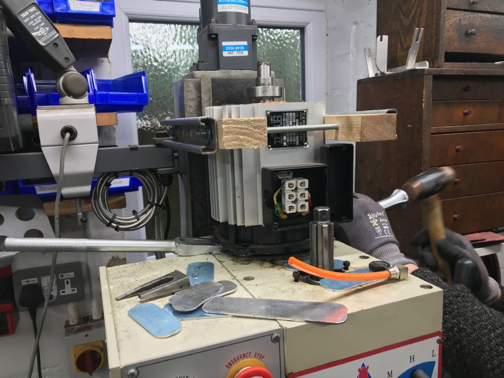
                                                  It took two of us, plus three large H/D flat blade screwdrivers, two of the old fashioned wedge type taper breakers and a couple of copper headed hammers and half hour of hammering and levering before it came free. It was absolutely solid in the spindle in the head.

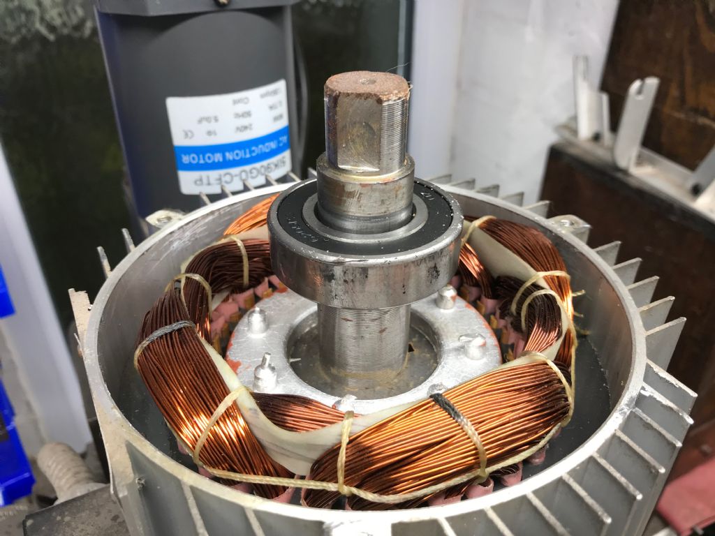
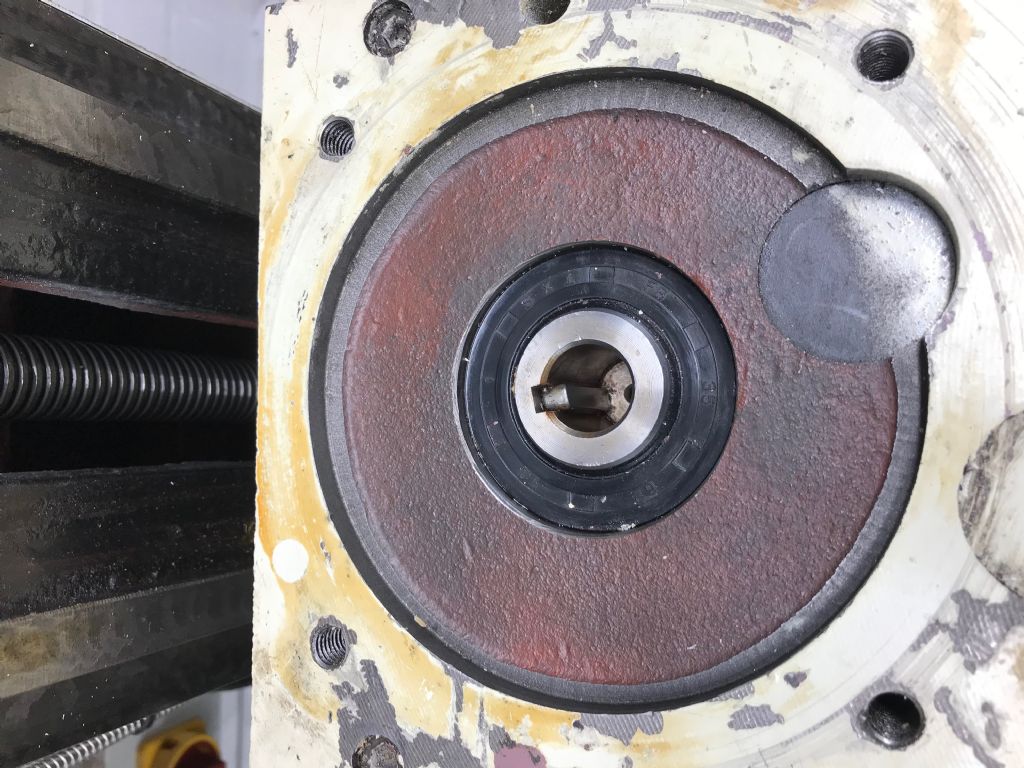
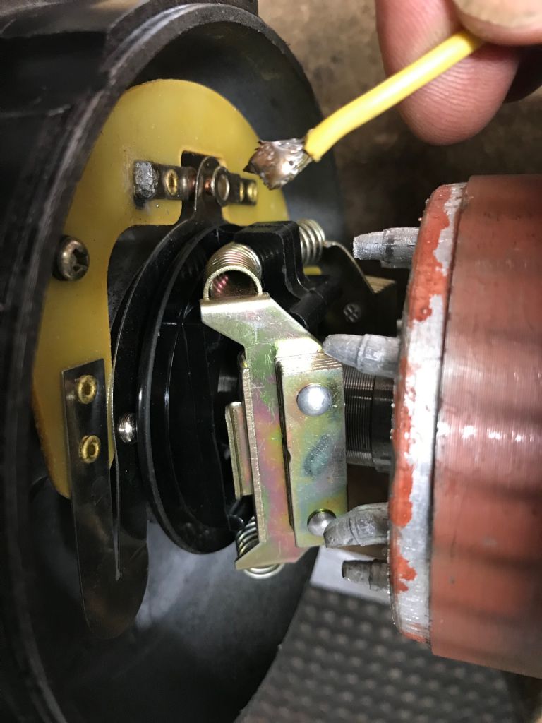
                                                  The centrifugal switch was at the spindle end of the motor. AS soon as the end case came of the problem was easy to see. No fault with the centrifugal switch per se, just a distinct lack of an electrical connection to it. A very dry solder joint had parted company .I only had a 40 watt soldering iron and to be honest this was a bit low powered, but with a good clean and a good dose of old fashioned soldering flux (Fluxite) the connection was remade. The pictures below show the effort to remove the motor, the faulty joint and motor location on the gearhead. Hopefully if anyone else has this problem these pictures might help.

                                                  All reassembled and works.

                                                  Many thanks to all those who made suggestions and particularly Les Jones 1 for his help in diagnosing the issue correctly.

                                                  img_4339.jpg

                                                  img_4341.jpg

                                                  img_4340.jpg

                                                  #386007
                                                  Clive Foster
                                                  Participant
                                                    @clivefoster55965

                                                    Glad you sorted it.

                                                    That keyed socket joint looks as if it might be airtight which would explain why it was so hard to separate. Been involved with a similar issue. Before putting it back together small air vent was added which made re-assembly and subsequent dismantling much easier.

                                                    Its also worth verifying the effective depth of the key. Another similar near impossible to dismantle pair of components was (probably) due to unfavourable tolerance build up making the key a touch thicker than the sum of the two keyway depths.

                                                    Don't want it to be uber tight on re-assembly because you don't know what is supporting the shaft at the bottom. If the gearbox top fixing bolts are reasonably accessible when the motor is in place it is possible that the motor shaft and gearbox shaft may have been pressed together as a unit trapping the gear box top plate and bearing between them. This would have allowed the fit to be deliberately made very tight to avoiding backlash issues and helping to ensure concentricity between the motor shaft and gearbox shaft.

                                                    When a single key is used light to moderate press fitting such components together is generally considered a better engineering solution than allowing the slight clearance needed for dismantling. Splines are the preferred choice if the assembly is expected to be separated as the drive area is much greater.

                                                    Clive.

                                                    #386025
                                                    Jon
                                                    Participant
                                                      @jon

                                                      Clive its tight on this woodruff key and decent fit of shaft. Combine that with a motor up high your back on the ceiling makes it hard to lift.
                                                      img_4341.jpg

                                                    Viewing 25 posts - 26 through 50 (of 50 total)
                                                    • Please log in to reply to this topic. Registering is free and easy using the links on the menu at the top of this page.

                                                    Advert

                                                    Latest Replies

                                                    Home Forums Manual machine tools Topics

                                                    Viewing 25 topics - 1 through 25 (of 25 total)
                                                    Viewing 25 topics - 1 through 25 (of 25 total)

                                                    View full reply list.

                                                    Advert

                                                    Newsletter Sign-up