Boxford VSL 500 Drive Pulley

Advert

Boxford VSL 500 Drive Pulley

Home Forums General Questions Boxford VSL 500 Drive Pulley

Viewing 25 posts - 1 through 25 (of 29 total)
  • Author
    Posts
  • #583028
    Roy Birch
    Participant
      @roybirch29994

      Hello All

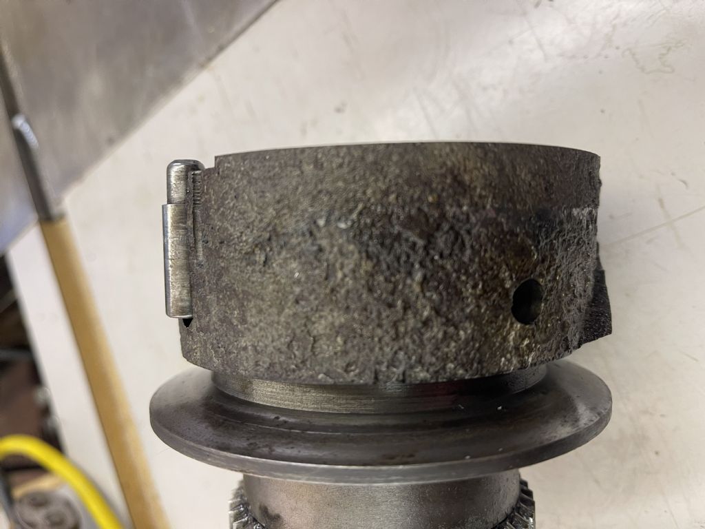
      I have tried parting off a 95mm blank of en3b and I noticed that the chuck kept slipping, I looked at the belt and all seemed ok, I then took the top cover on the headstock off only to find that a section of the drive pulley had broken away as well as the body holding the pins, a repair had been done by a previous owner which was to put insulation tape around the pulley main body to hold the pins in. Does anyone have a idea of how to repair this or where I might find another pulley?

      regards

      Roy

      Advert
      #28548
      Roy Birch
      Participant
        @roybirch29994
        #583040
        Hopper
        Participant
          @hopper

          Pics sure would help. Otherwise it's maybe a choice of weld it, make a new one from scratch or buy a replacement off eBay etc. If it's diecast Mazak potmetal like a Myford, welding is out of course but maybe some other cunning plan involving adhesives and reinforcing rings etc might work better than insulation tape? Pics sure would help.

          #583046
          Roy Birch
          Participant
            @roybirch29994

            I will get a picture, the problem is that the chunk of cast iron that is missing also forms the inside wall of the pulley.

            #583059
            Roy Birch
            Participant
              @roybirch29994

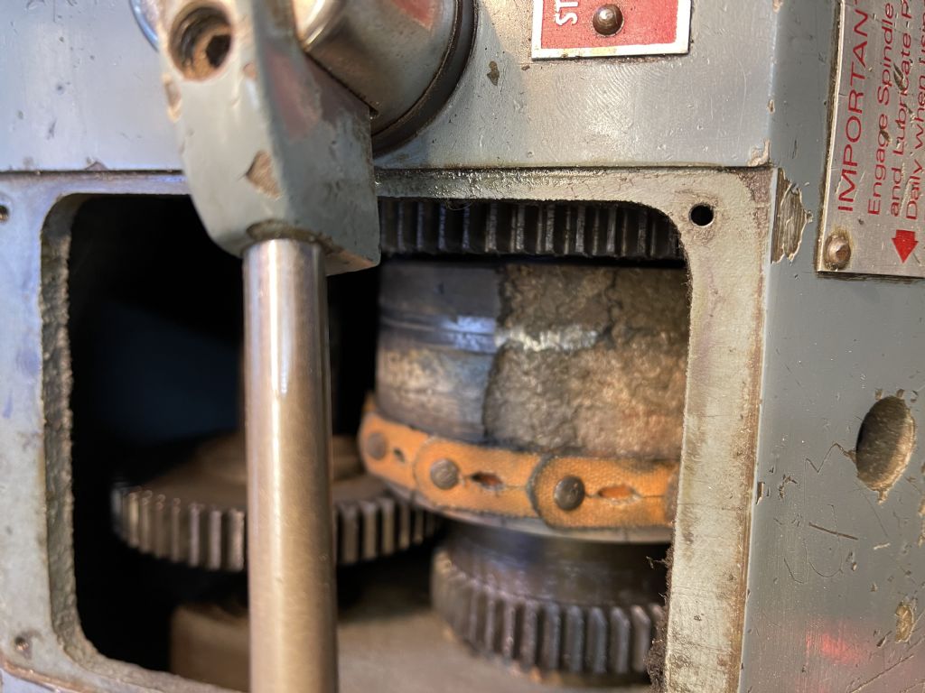
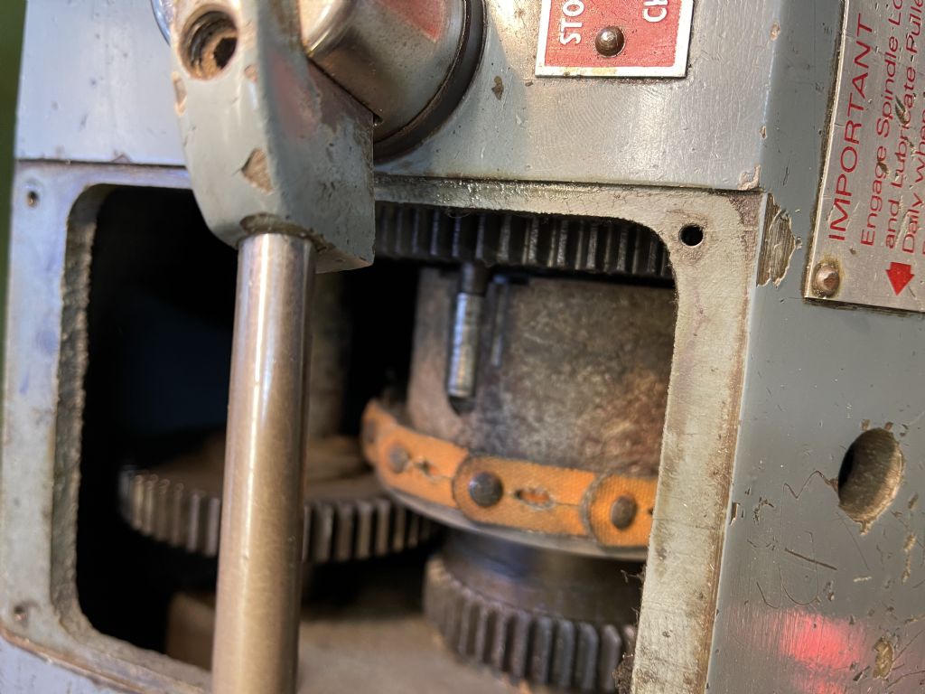
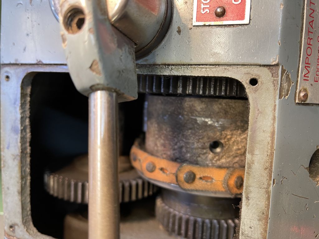
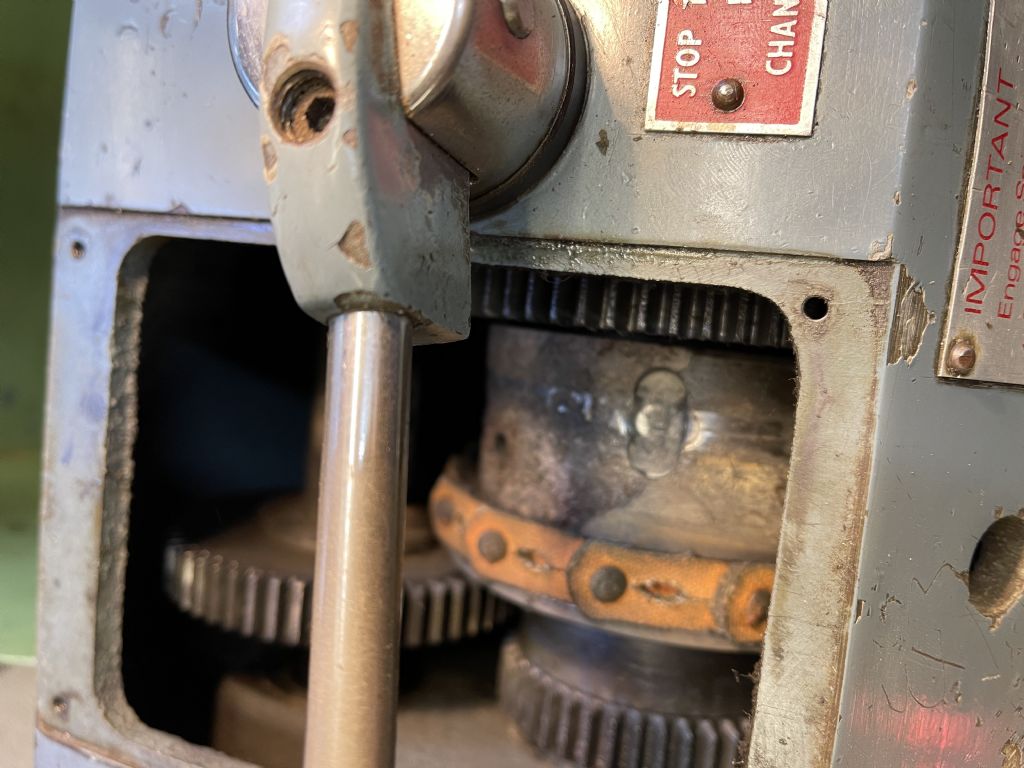
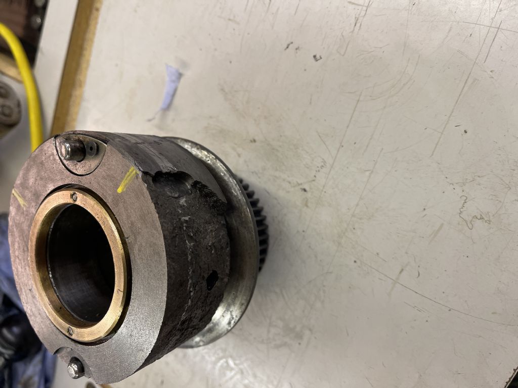
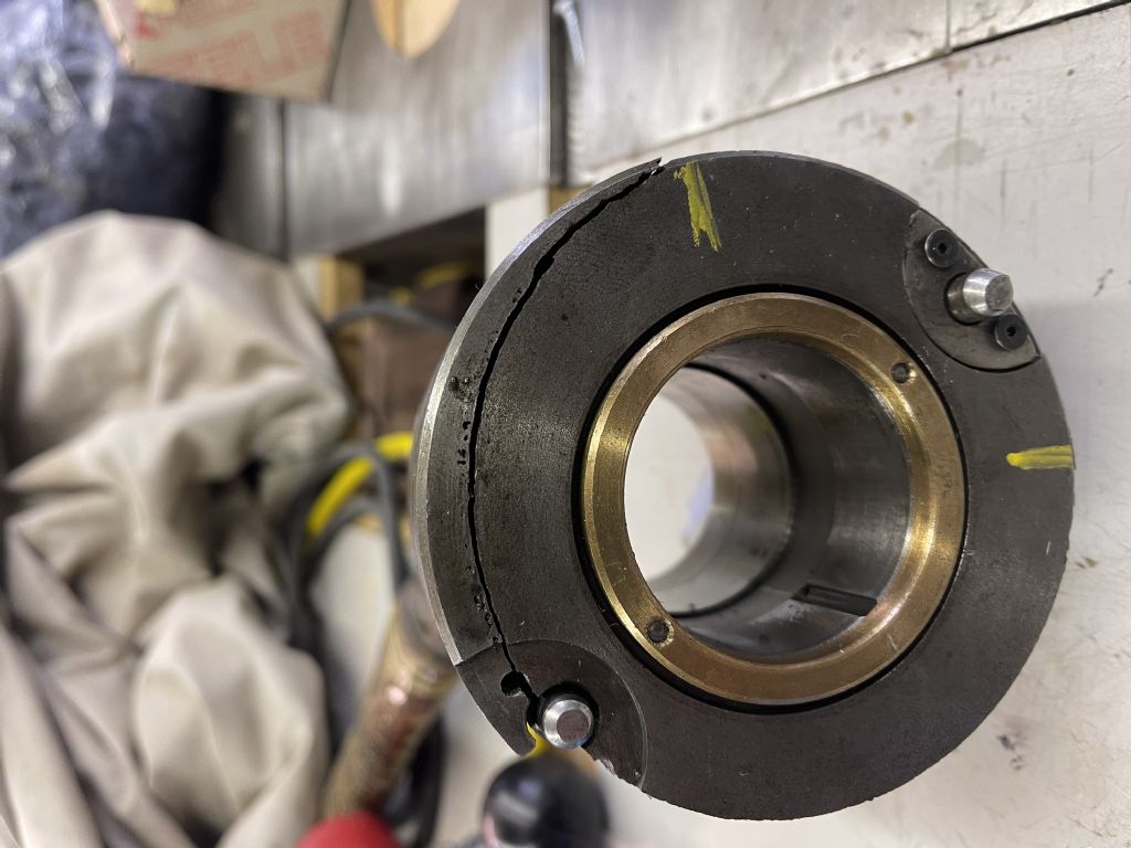
              img_0648.jpgimg_0647.jpgimg_0646.jpgimg_0645.jpgThe delamination of the cast iron is at max 3mm deep where the drive pin is, the delamination travels 1/3 of the circumferance of the pulley and is exactly from jaw 1 to jaw 2 on the chuckimg_0644.jpg

              #583060
              Roy Birch
              Participant
                @roybirch29994

                The delamination of the cast iron is at max 3mm deep where the drive pin is, the delamination travels 1/3 of the circumferance of the pulley and is exactly from jaw 1 to jaw 2 on the Chuck

                #583061
                Clive Foster
                Participant
                  @clivefoster55965

                  I have welded a patch piece into a cast iron pulley wall and filed to shape with acceptable results but it was certainly a last resort job. Got things up and running until I could make a replacement. I suspect the patch piece was a lump of steel. It was never going to be a permanent job.

                  Clive

                  #583064
                  Roy Birch
                  Participant
                    @roybirch29994

                    The photos are in the wrong order, they start at the bottom

                    #583068
                    Roy Birch
                    Participant
                      @roybirch29994

                      I suspect the problem is that someone either pushed the spindle lock in whilst the machine was running or a chuck got stuck and they used too much force with the spindle lock engaged, I dont have the facility to make a new one as I would want the main headstock pully out of the machine to make test fits and I dont have another lathe I could use.

                      Regards

                      Roy

                      #583069
                      Hopper
                      Participant
                        @hopper

                        Mmm that looks nasty. Not sure what you mean exactly about the inner wall, as I am not familiar with that particular lathe. But it looks like something might be done along the lines of taking the pulley out and machining the OD down and then turning up a steel repair ring and shrinking it on then securing with pins or screws etc. Or you might have to cut that whole section off and turn up a complete ring and attach it somehow to the rest of the pulley. Either way, looks like major work.

                        #583071
                        Hopper
                        Participant
                          @hopper

                          PS cross posts. If you don't have facility for a major job like that, could a very large Jubilee clip type of hose clamp be substituted for the electrical tape as a temporary bodge? Or a purpose made band of sheetmetal with a clamp arrangment on the ends to pull them together?

                          #583074
                          Roy Birch
                          Participant
                            @roybirch29994

                            The main problem is that the lathe is slipping due to the wall of the drive pulley being cast into the part that is missing so even if I tried to make a new one it would be difficult on this lathe.

                            #583076
                            Clive Brown 1
                            Participant
                              @clivebrown1

                              I'd think the chances of finding another VSL pulley are very slim. I wonder if the standard 4-step Boxford pulley would fit. I think that the pin arrangement might be similar, but my ME10 pulley is aluminium, but awkward to see the detail inside the headstock.

                              There is a dealer by the name of Ostia Tools that sells Boxford components on Ebay. A long shot but might be worth giving them a call. There maybe others as well.

                              #583078
                              Roy Birch
                              Participant
                                @roybirch29994

                                The main problem is that the VSL500 has a 1 3/8 bore which is nearly twice the size of the standard machines, it may of course be close on external diametre

                                #583105
                                Roy Birch
                                Participant
                                  @roybirch29994

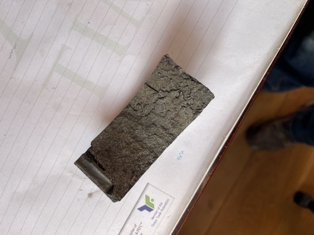
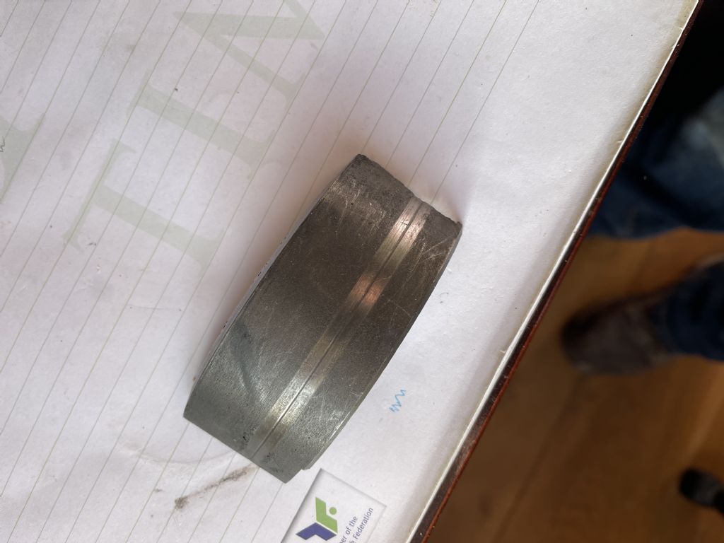
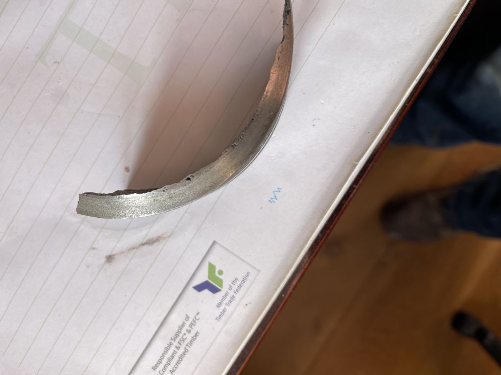
                                  So upon further investigation I have found 2/3 of the missing piece, whoever was operating this Boxford at the time left this inside nicely against the drive belt, photo 1 shows the inside, photo 2 shows the outside which also shows that someone was trying to use the spindle lock with the chuck still turning and photo 3 is the reason for the belt slipping as this is the inside wall of the belt pulley, does anyone think this is user error or was the casting suspect in the first place? and does this piece and I am sure I will find the other bits iside the headstock somewhere make a repair more likely?

                                  img_0651.jpgimg_0650.jpgimg_0649.jpg

                                  #583148
                                  Niels Abildgaard
                                  Participant
                                    @nielsabildgaard33719

                                    It has been my pleasure to save a VSL from a fate worse than death.

                                    v__7b36[1].jpeg

                                    I had one and had decided to give it a new spindle and a state of art drive system.

                                    Had the angle grinder ready to cut the nose of the spindle .Back plate was stuck solid.

                                    In the final second I stopped my self and sold it of to a man who restores old cars.

                                    My plan was to put a poly-v disc directly on spindle and drive it from a 3-4kW 4 or 6 pole AC motor from a 2.2kW VFD

                                    I did something like it many years ago on a clas A standard.

                                    When I lacked torque I upped speed and lowered depth of cut.

                                    VFD drive of Boxford

                                    Edited By Niels Abildgaard on 30/01/2022 17:20:34

                                    Edited By Niels Abildgaard on 30/01/2022 17:23:10

                                    Edited By Niels Abildgaard on 30/01/2022 17:23:58

                                    Edited By Niels Abildgaard on 30/01/2022 17:26:41

                                    #583167
                                    DiogenesII
                                    Participant
                                      @diogenesii
                                      Posted by Hopper on 30/01/2022 12:35:02:

                                      PS cross posts. If you don't have facility for a major job like that, could a very large Jubilee clip type of hose clamp be substituted for the electrical tape as a temporary bodge? Or a purpose made band of sheetmetal with a clamp arrangment on the ends to pull them together?

                                      Hmm, how about the flat steel 'crimp-on' clips used for CV-joint boots?

                                      I wonder if JB Weld (metal-fillered 2 part epoxy) would have enough wear resistance to build up the pulley cheek in order to at least get you up & running again?

                                      #583225
                                      Hopper
                                      Participant
                                        @hopper

                                        Or, you might be able to do something with fibreglass. It is very strong if you use epoxy resin instead of the usual polyester resin with the woven glass matting. Or one step further and use carbon fibre, I know nothing much about either so seek expert advice. Boat builders use it a lot and might know about high strenght applications. You might need to embed metal inserts for the holes where the pins engage.

                                        #583228
                                        Speedy Builder5
                                        Participant
                                          @speedybuilder5

                                          Just seen Roys post (after I had just typed this up) – I agree with his diagnosis as this is very similar to the Boxford AUD.

                                          Looking at photo 5, it may be that the damage was initially caused by the spindle lock pin shearing the slice off of the pulley. If there had been a stuck chuck and excessive force was used to remove it, that force would have been transmitted through spindle lock pin and then the machined slot in the pulley. Incidentally, there is a wear mark on the piece which sheared off. Was that caused by the spindle lock pin ?

                                          Hopper's idea may be the best way forward -If you have access to another larger lathe.

                                          Bob

                                          #583309
                                          Roy Birch
                                          Participant
                                            @roybirch29994

                                            img_0652.jpgimg_0653.jpgimg_0654.jpgimg_0655.jpgimg_0656.jpg

                                            #583311
                                            Roy Birch
                                            Participant
                                              @roybirch29994

                                              Hello All

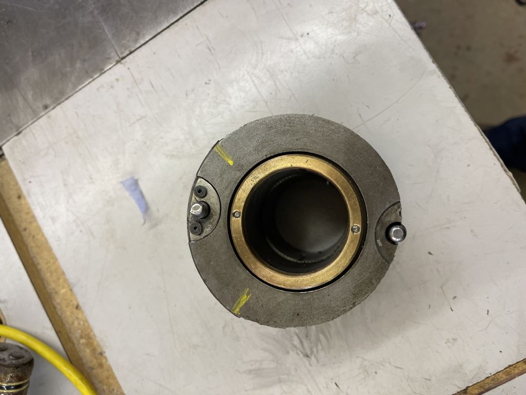
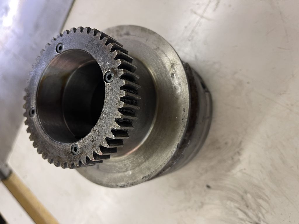
                                              So here is the pulley out of the machine, the drive gear shows some elongation of the holes for the drive pins so I think this lathe may have been put into back gear with the shaft still turning,

                                              Photo 1 shows the area that is missing from the pulley, this distance is at least 2/3rds of the pulley missing some material.

                                              Photo 2 shows why the lathe had a lot of slippage

                                              Photo 3 seems to indicate that this is made in 2 parts as there is a golden ring around the part that holds the back gear which I assume is silver solder.

                                              Photo 4 shows the deepest part of the damage with very little pulley side left.

                                              Photo 5 shows the piece that I found against the drive belt in place on the pulley block.

                                              This pulley block is different from the normal AUD as this one is solid and the AUD block is machined to have an internal hub which I assume has a lot to do with weight so any other replacement has to be the same as you would machine most all of the internal hub away. I now dont think the repair is feasible unless I drilled a new spindle lock hole in the undamaged area of the pulley and a new button oiler hole which runs into the small keyway in photo 5.

                                              Regards

                                              Roy

                                              #583312
                                              Roy Birch
                                              Participant
                                                @roybirch29994

                                                One more thing to add is that I now believe this casting is at fault because the two pins in photo 5 should have sheared off befor the casting took any damage

                                                #583339
                                                Dave Halford
                                                Participant
                                                  @davehalford22513

                                                  Looks like there's a crack on the pulley side as well.

                                                  #583348
                                                  Roy Birch
                                                  Participant
                                                    @roybirch29994

                                                    No that’s not a crack it’s the piece that was broken off which I have just placed on the hub

                                                    #583352
                                                    Dave Halford
                                                    Participant
                                                      @davehalford22513
                                                      Posted by Roy Birch on 31/01/2022 16:50:06:

                                                      No that’s not a crack it’s the piece that was broken off which I have just placed on the hub

                                                      Gear side photo so the other side of the pulley, there's a spiral of little black spots

                                                    Viewing 25 posts - 1 through 25 (of 29 total)
                                                    • Please log in to reply to this topic. Registering is free and easy using the links on the menu at the top of this page.

                                                    Advert

                                                    Latest Replies

                                                    Home Forums General Questions Topics

                                                    Viewing 25 topics - 1 through 25 (of 25 total)
                                                    Viewing 25 topics - 1 through 25 (of 25 total)

                                                    View full reply list.

                                                    Advert

                                                    Newsletter Sign-up