Alyn RLE Last and First
Alyn RLE Last and First
- This topic has 43 replies, 13 voices, and was last updated 13 August 2024 at 06:57 by
 derek hall 1.
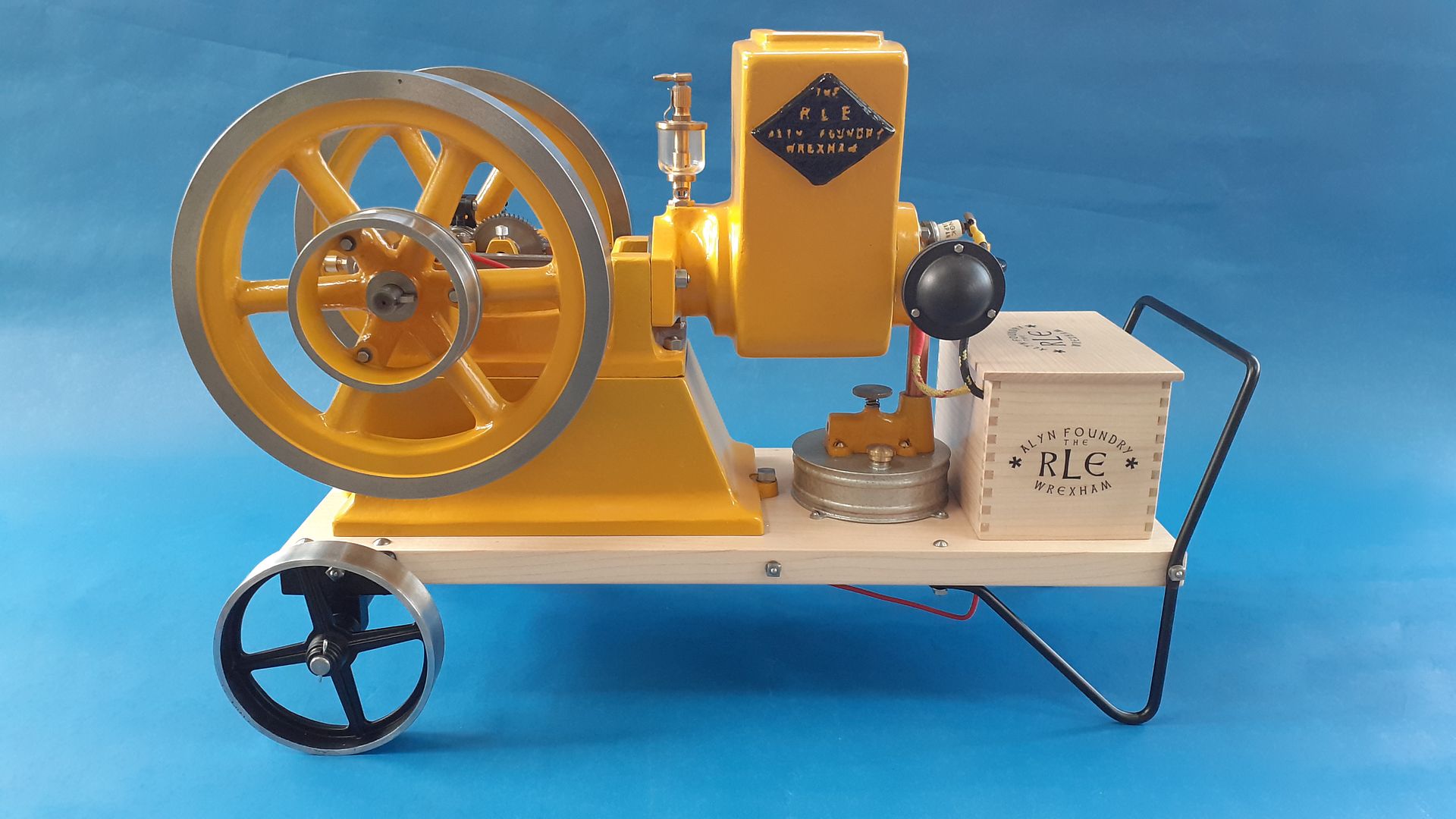
![20230802_162555[1]](https://www.model-engineer.co.uk/wp-content/uploads/sites/4/hm_bbpui/701139/u2fju7cacngg2fbnyra856s6rpoe2zba.jpg)
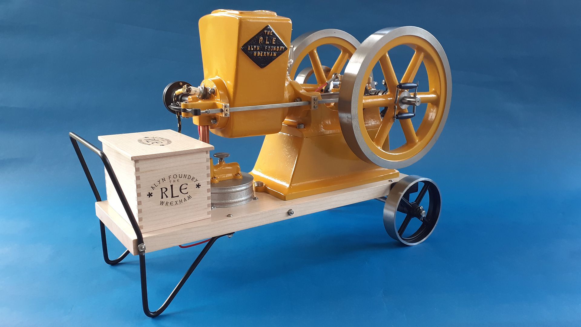
![20230806_083159[1]](https://www.model-engineer.co.uk/wp-content/uploads/sites/4/hm_bbpui/701139/idsblm8qfbt1retjaip7m1vl5jgtf2nj.jpg)
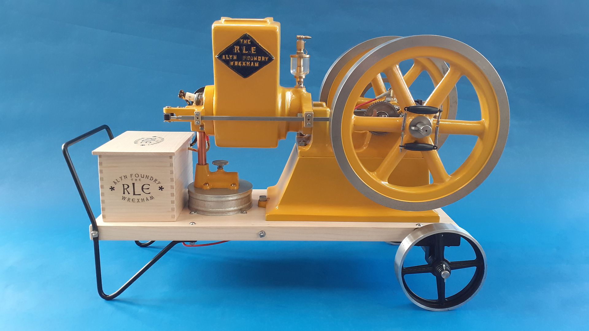
![20230806_083541[1]](https://www.model-engineer.co.uk/wp-content/uploads/sites/4/hm_bbpui/701139/gk5325ycbo2zkr08cb33skuoyhngn6zf.jpg)
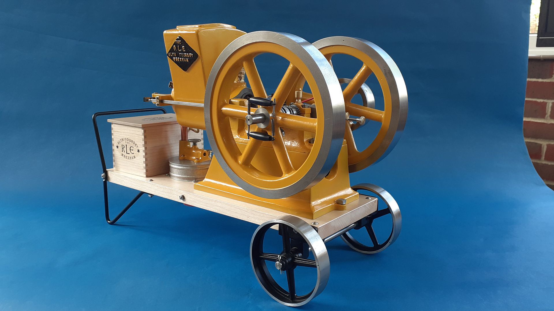
![20230806_085914[1]](https://www.model-engineer.co.uk/wp-content/uploads/sites/4/hm_bbpui/701139/taf4m8892vfhy7k34pembp3ph3m2ba4y.jpg)
![20230806_092255[1]](https://www.model-engineer.co.uk/wp-content/uploads/sites/4/hm_bbpui/701139/mcheud7weqk26sq0ef590dv6x6zqwvrg.jpg)
![20230806_122235[1]](https://www.model-engineer.co.uk/wp-content/uploads/sites/4/hm_bbpui/701139/ci8t7xp9c0w27izwjb1lctinmyjtco9s.jpg)
- Please log in to reply to this topic. Registering is free and easy using the links on the menu at the top of this page.
Latest Replies
-
- Topic
- Voices
- Last Post
-
-
Running 380V 3-phase motor on 230V 1-phase
1
2
Started by:
jimalm
in: Electronics in the Workshop
- 14
-
23 June 2026 at 23:06
Robert Atkinson 2
-
Testing Single Point Thread Fitment
Started by:
berwick
in: Beginners questions
- 12
-
23 June 2026 at 22:25
alecs
-
Rapidor 3XM
Started by:
homecat88
in: Introduce Yourself – New members start here!
- 2
-
23 June 2026 at 22:11
Nicholas Farr
-
digital microscope for poor eyesight
Started by:
bernard towers
in: Electronics in the Workshop
- 10
-
23 June 2026 at 21:32
Nigel Graham 2
-
Gas Tap Valves. Vintage
1
2
3
Started by:
dee
in: Related Hobbies including Vehicle Restoration
- 19
-
23 June 2026 at 21:24
Nigel Graham 2
-
Taylor Hobson Pantograph Engraver Model D
1
2
Started by:
jaCK Hobson
in: Workshop Tools and Tooling
- 10
-
23 June 2026 at 21:05
Charles Jambon
-
Model Turbines
1
2
…
26
27
Started by:
Turbine Guy
in: Stationary engines
- 28
-
23 June 2026 at 20:21
Turbine Guy
-
Rapidor Manchester re-build
Started by:
homecat88
in: Introduce Yourself – New members start here!
- 3
-
23 June 2026 at 19:19
homecat88
-
Advice required
Started by:
janet.ho001
in: Introduce Yourself – New members start here!
- 4
-
23 June 2026 at 19:12
janet.ho001
-
Orbital – Not your Usual Oscillator!
1
2
Started by:
JasonB
in: Stationary engines
- 14
-
23 June 2026 at 19:11
JasonB
-
Clarkson Horizontal – Redefined in Metric
Started by:
JasonB
in: Stationary engines
- 8
-
23 June 2026 at 18:48
JasonB
-
3D Printing in the Home Workshop
Started by:
Colin Heseltine
in: 3D Printers and 3D Printing
- 3
-
23 June 2026 at 17:01
Fulmen
-
Hot radiators in summer
Started by:
Gary Wooding
in: The Tea Room
- 7
-
23 June 2026 at 12:13
JasonB
-
Rob Roy Build
Started by:
Dalboy
in: Locomotives
- 4
-
22 June 2026 at 21:24
Dalboy
-
Help identifying a mystery thread
Started by:
Beardy Mike
in: Beginners questions
- 8
-
22 June 2026 at 19:04
Nicholas Farr
-
Unwanted Car Software Update
Started by:
Chris Crew
in: The Tea Room
- 12
-
22 June 2026 at 16:48
paul1956
-
Oiling Lathe Ways
Started by:
Blue Heeler
in: Beginners questions
- 7
-
22 June 2026 at 13:34
Bazyle
-
Farm Boy dimensions
Started by:
Speedy Builder5
in: Stationary engines
- 3
-
22 June 2026 at 13:02
JasonB
-
Nickel Silver
Started by:
Carl
in: Materials
- 10
-
22 June 2026 at 11:52
Roderick Jenkins
-
Flame Licker Engine & USA made 1930’s Empire Water Pump
Started by:
Blue Heeler
in: Miscellaneous models
- 2
-
22 June 2026 at 10:03
Bazyle
-
Film Projectors/Astronomy/Radio Ham-Mark Stuckey
Started by:
Mark Easingwood
in: Related Hobbies including Vehicle Restoration
- 1
-
21 June 2026 at 22:40
Mark Easingwood
-
Baffled by flatted-shank spot weld drills
Started by:
Bill Phinn
in: Workshop Tools and Tooling
- 4
-
21 June 2026 at 22:26
Bill Phinn
-
Wallace valvegear simulator
1
2
Started by:
Kevan Shaw
in: General Questions
- 7
-
21 June 2026 at 21:32
Kevan Shaw
-
All things Beaver Mill
1
2
…
9
10
Started by:
Robert James 3
in: Manual machine tools
- 43
-
21 June 2026 at 21:16
Mark Rand
-
Green Dragon Sustainable Fuel
Started by:
Neil Wyatt
in: Locomotives
- 14
-
21 June 2026 at 21:07
Mark Rand
-
Running 380V 3-phase motor on 230V 1-phase
1
2
Latest Issue

Newsletter Sign-up
Latest Replies

