A very small Shaping Machine …

Advert

A very small Shaping Machine …

Home Forums Manual machine tools A very small Shaping Machine …

Viewing 25 posts - 101 through 125 (of 127 total)
  • Author
    Posts
  • #134239
    IanT
    Participant
      @iant

      John, whilst I don't disagree with you with respect to what a larger shaper can do (or it's potential accuracy) I think there are a couple of other considerations here apart from just the size.

      As I've stated, I have both a hand shaper and a powered one. Whilst a powered shaper is generally a very safe machine it can almost lull you into being a bit too familiar with it (and then it can be very dangerous). So I am beginning to see that some things are better done on the hand shaper, where I can for instance "nibble" at things in a more controlled (e.g. safer) way – something that I wouldn't really want to try on a bigger machine under power.

      I am also looking at a good way to limit the stroke by settable stops (for engraving dials for instance) on the hand shaper, again something that I wouldn't really try to do on a powered machine.

      So yes, for a good finish & sizing work (be that flat surfaces, gib pieces, dovetails etc) a powered Shaper is great but for small work that is more akin to engraving or for what I think of as "shaving" parts then I think a smaller (shaper-type) hand powered machine might be preferable and much safer

      Regards,

      IanT

      Advert
      #134241
      Michael Gilligan
      Participant
        @michaelgilligan61133
        Posted by John Olsen on 31/10/2013 09:59:44:

        A four inch shaper is not really all that small …

        But actually I wonder how important it is for the shaper to be that small anyway? I have a 6 inch Ammco machine that I think would do the sort of work required.

        John Olsen

        .

        John,

        Thanks for your thoughts …

        This may not be entirely clear from my opening post, but: I am not so much looking for "a very small machine" as a machine which "typically working within a small envelope [say, 100mm cube] can do very small work".

        I am thinking in terms of 10 micron increments for the "feed" [maybe less, if I use a Stepper Motor], and some of the shapes cut would be smaller than the thickness of the swarf from some large Shapers.

        Whilst is is possible to make a large machine which is very precise … it is usually also very difficult and very expensive. This is my main reason for assuming a small machine.

        Very happy to be proved wrong … but I hope you see the logic.

        MichaelG.

        #134244
        Bazyle
        Participant
          @bazyle

          In many respects you might need to be bigger to work smaller. Take for example the saddle on a cheap 4in lathe. It is probably about 6 inches long on the bed. A good toolroom lathe, also just 5in centre height will have a saddle 18 in long. The extra length provides the necessary alignment and rigidity to work to tenths. So I think the Adept and Drummond hand shapers are the size of structure you would want to get to your target so perhaps you could fabricate a sort of copy, but using ball slides for precision.

          #134245
          North Western
          Participant
            @northwestern

            I think Ian makes some interesting points regarding hand power for certain types of work.
            For a number of delicate jobs using my motorised Adept 2, I slackened the belt and used a handle attached to the drive pulley. This was slow compared with direct hand lever drive, but did give excellent control, and was worth the effort. The cuts were very fine and some of the tools very small, but there were no breakages and no foul-ups. Because of the mass I was moving through rotary action, I was tempted to strip off the motorised components as an experiment just to compare the sensitivity and feedback of hand operation with a lever, but never found the time unfortunately. However, my handle also enabled work to continue through some particularly long power cuts!

            Dave

            #134246
            Michael Gilligan
            Participant
              @michaelgilligan61133

              Bazyle and Dave,

              Very fair points … My thinking is spiralling at present, but eventually might settle to something that works for me.

              Please keep the ideas coming.

              Thanks everyone !

              MichaelG.

              #134250
              jason udall
              Participant
                @jasonudall57142

                Scraper vs shaper….

                #134254
                dcosta
                Participant
                  @dcosta

                  Hello Michael, good afternoon.

                  After reading all the posts of the participants on the subject "A very small Shaping Machine … " and especially your reactions to them, I am convinced that if I were in your place I would choose to build a machine from scratch using Dave Gingery plans and modifying them in accordance with my goals.
                  1 – It's the more plastic solution because it allows to be thought a priori to serve your objectives. Not by modifying a used machine.
                  2 – Unlike a solution with castings, if any error occurs you don't need to buy a replacement.
                  3 – Unlike a casting solution allows corrections.
                  4 – It's is probably the cheapest solution.
                  5 – Allows, like Dave ( Noth Western )
                  wrote in its post, for installation of a pulley handle for short controlled movements (even possible to install a scale and travel stops on the pulley) if you choose to build with the use of synchronous pulley and belt.
                  6 – If you want the advances to be controlled by stepper motors do not need to make adjustments, because you can think of solutions from the start.
                  7 – In limit you even can control the movement of the ram with a
                  sufficiently powerful and well controlled (for no hiccups motion) stepper motor.

                  Best regards
                  Dias Costa

                  #134259
                  Michael Gilligan
                  Participant
                    @michaelgilligan61133
                    Posted by jason udall on 31/10/2013 15:39:22:
                    Scraper vs shaper….

                    .

                    Call it what you will, Jason

                    If it works like a Shaper, and clacks like a Shaper; then I would say it's a Shaper.

                    MichaelG.

                    Edited By Michael Gilligan on 31/10/2013 18:20:18

                    #134274
                    Sub Mandrel
                    Participant
                      @submandrel

                      Random musings… I've been thinking about this. For a shaper to work, it needs a number of things:

                      Great rigidity of the central structure with the ram and sideways movement on top and the table with its vertical movement on the front. This suggests a box structure, a large, thick piece of angle reinforced with webs or even a great big chunk of epoxy-based stuff.

                      The ram slide should be as long as possible. It seems a sliding bearing on a rod can be as effective as a dovetail in this role.

                      All the forces in a shaper act to pull (or push) the slides apart. This is the opposite of most sliding surfaces on a lathe and means dovetail slides may not be the best or only solution (as they will only bear the load on the angled surfaces, and maximising the bearing area), however, any solution needs to be adjustable to absolutely minimise play. Some alternative designs shown in my old copy of Machinery's Handbook might prove suitable.

                      Fixed slideway lengths needs to be a minimum of the size of the moving part plus the travel. How big should the moving parts be?

                      A 1mm pitch leadscrew from studding with a 40-tooth ratchet would give feed down to 1 thou, with pawl with varying gathering. This is probably too fine.

                      Neil

                      #134278
                      jason udall
                      Participant
                        @jasonudall57142

                        Mickael..
                        I don’t know either subject well enough to pass judgment ..I suspect that it is as you say the result is the all…

                        #134280
                        Howard Lewis
                        Participant
                          @howardlewis46836

                          Good evening Michael,

                          You are planning to make feed increments of 10 microns? Or did I misread your post?

                          The tools will need to be ABSOLUTELY sharp, to cut. This is the realm of precision grinding.

                          Some comparisons with the accuracy to which you aspire.

                          In old money, 10 microns is just under 4/10 of a thou, about 25% more than a tenth of the thickness of a blonde human hair, (darker hair is thicker).

                          Sorry to be a wet blanket, but you are going to have to do some REAL precision engineering to be able to advance, consistently, by that amount. I would imagine that you are approaching the realms of the type of machinery used in a Standards Room to check and calibrate the shopfloor measuring equipment used in a fairly precise factory.

                          (Slip gauges are check measured to an accuracy of millionths of an inch under conditions of controlled temperature and humidity, after at least 24 hours to soak to the 20 degrees C ambient condition). I have seen a Height Gauge with an error of 0.002 inches over 18 inches ( 0.00011/inch or 2.8 microns/ mm) condemned.

                          An Imperial Verdict finger clock has one division equal to 1/10 thou or 2.54 microns).

                          The backlash in a good leadscrew / nut assembly is going to be much greater than that, unless some special backlash elimination is included!

                          A pair of components, such as the Head and Rotor in a distributor type Fuel Injection Pump, or Injector Needle and Nozzle Body, which have been lapped together, (and therefore not interchangeable with other supposedly identical components), have a clearance of 1 to 2 microns, MAXIMUM.

                          Your design should include space for micrometer dials at least 100mm in diameter, with a 1mm pitch leadscrew., if you are to have divisions which allow a resolution of the order of 10 microns.

                          And, if you want to achieve that degree of accuracy, consistently, start thinking in terms of a very closely controlled temperature in your workshop.

                          As I said, I don't want to be negative, but you do need to think realistically about the degree of accuracy that you WANT versus what you can actually ACHIEVE.

                          Howard

                          #134297
                          Michael Gilligan
                          Participant
                            @michaelgilligan61133
                            Posted by Howard Lewis on 31/10/2013 22:05:02:

                            Good evening Michael,

                            You are planning to make feed increments of 10 microns? Or did I misread your post?

                            The tools will need to be ABSOLUTELY sharp, to cut. This is the realm of precision grinding.

                            The backlash in a good leadscrew / nut assembly is going to be much greater than that, unless some special backlash elimination is included!

                            Howard

                            .

                            Good morning Howard

                            I have woken rather too early, and popped down for coffee before going back to bed; so this is just a brief response to your three main points:

                            1. Yes, 10 microns [Note: My favourite microscope, made in 1946, has a fine-focus mechanism with one micron divisions on the dial, so I don't consider this unreasonable]. I am thinking of using a 2mm pitch leadscrew, and a dial with 200 divisions [in anticipation of adding a Stepper Motor in due course.]
                            2. Agreed
                            3. Agreed. I expect to use either a BallScrew, or a Nut with backlash adjustment [similar to the design used on the slides of my BCA]

                            At the risk of labouring the point … I want to build something that works like a workshop Shaper, but on a scale that allows me to cut very small details. The main perceived benefit of a Shaper is that it uses a simple cutter … which is very convenient, and cost-effective, for repair/restoration work.

                            Thanks for your "Sanity Check"

                            MichaelG.

                            #134303
                            jason udall
                            Participant
                              @jasonudall57142

                              Michael..from memory ..some microtomes use a rocking arm heated using temp. control to extend the specimen to the “knife”..a control system from a 3d printer springs to mind..you have heater control ( three channels) micro stepper drives ( 200*16 steps) 5 channels. … free..control software.. potential for stand alone ( pc less) use…
                              And fairly cheap. ….

                              #134304
                              jason udall
                              Participant
                                @jasonudall57142

                                Another thought….micrometer screws..how do they deal with backlash..?
                                ….I think its because they operate one direction (as one does to null out backlash)..and that might work in this context. .tool carrier motion dead..work advances to tool one direction…
                                Btw height gauge at work 0.1 micron..achived using strain gauges measuring the contact force..at the point of recording value…very consistant..as one would expect from the land of cuckoo clocks and chocolate

                                #134310
                                Sub Mandrel
                                Participant
                                  @submandrel

                                  > some microtomes use a rocking arm heated using temp. control to extend the specimen to the "knife"

                                  Alternatively just wait for the tide to go out

                                  Neil

                                  #134312
                                  John McNamara
                                  Participant
                                    @johnmcnamara74883

                                    Hi Jason

                                    Beware of micro stepping, Just because your software divides by 16 does not increase the resolution by a similar amount. Micro stepping works by tweaking the phase angle of the electronics driving the normally 200 step motor. There is significant non linearity.

                                    **LINK**

                                    Or a more general search:**LINK**

                                    Chasing microns is not just a matter of cranking up the gearing.

                                    One of the reasons most industrial machines use glass scales attached to the sliding member allowing the software to know where the slide and tool is regardless of mechanical backlash and any non linearity in the drive system. coupled to a servo. (Although some better end stepper drivers allow the use of a reference scale or encoder). That has the additional benefit of closing the loop, the driver will compensate for lost steps using the scale or encoder as a reference.

                                    However even glass slides do not allow the system to absolutely position the tool in relation to the part, due to geometric errors and temperature effects on the frame and slide assembly.

                                    Micron accuracy is an elusive prey.

                                    Regards
                                    John


                                    Edited By John McNamara on 01/11/2013 11:19:21

                                    #134313
                                    Ian P
                                    Participant
                                      @ianp
                                      Posted by jason udall on 01/11/2013 09:36:46:
                                      Another thought….micrometer screws..how do they deal with backlash..?
                                      ….I think its because they operate one direction (as one does to null out backlash)..and that might work in this context. .tool carrier motion dead..work advances to tool one direction…

                                      Micrometers rely on very accurate close fitting threads, triangular/trapezoidal thread usually adjusted by closing reducing the 'nut' female thread diameter. As you say they only need to be free of backlash in one direction only but in practice any free movement is too small to be of consequence.

                                      A leadscrew and nut is capable of very high precision but the key to achieving it is to have extremely long engagement between the screw and nut so that any errors are averaged out.

                                      Ian P

                                      #134343
                                      jason udall
                                      Participant
                                        @jasonudall57142

                                        s to micro stepping..I to never really convinced… ( open loop control of any type for that matter )

                                        What a shame waldo s don’t really work..

                                        As to long engagment leadscrew..I think thats how it was originally done…one leadscrew clamped between two blocks of wood..which averaged the pitch…then this was used to screw cut another..more accurate ls..and so on…whitworth needed to start somewhere

                                        ( )

                                        #134344
                                        jason udall
                                        Participant
                                          @jasonudall57142

                                          Just remembered

                                          On the infeed of our centerless grinders ( 1/10 thou)…the feed works by a hydraulic ram moving a cam ( may be ramp is a better description ) past the end of the infeed slide… with 20 inches of cam for as near parallel as you chose ( say 20 thou ) and seting stops to again say 20 thou.. this gives 20 micro inch …but yes non linearity is present…just how straight / flat is the cam..

                                          #134346
                                          Michael Gilligan
                                          Participant
                                            @michaelgilligan61133
                                            Posted by John McNamara on 01/11/2013 11:01:44:

                                            Hi Jason

                                            Beware of micro stepping, Just because your software divides by 16 does not increase the resolution by a similar amount. Micro stepping works by tweaking the phase angle of the electronics driving the normally 200 step motor. There is significant non linearity.

                                            Regards
                                            John

                                            .

                                            Very true, John

                                            That's why I settled on 2mm pitch leadscrews to achieve my 10 micron feed increment.

                                            I do have a couple of 800 steps per rev. motors, but I'm saving those for something really special.

                                            They are NEMA 17 size … Precision engineering in mass production.

                                            MichaelG.

                                            #134376
                                            John McNamara
                                            Participant
                                              @johnmcnamara74883

                                              Hi All

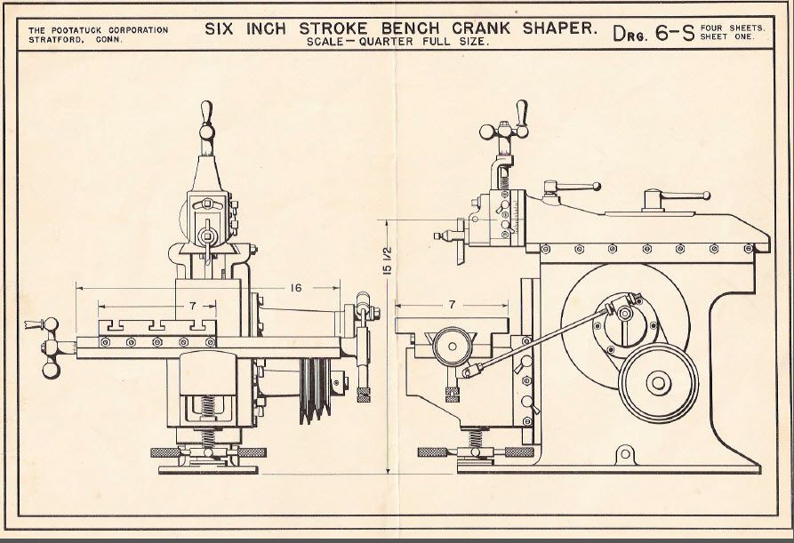
                                              There is a very fine set of shaper drawings (4 pages) Here:

                                              **LINK**

                                              You have to register I had no problems.
                                              A good project for epoxy concrete castings

                                              Regards
                                              John

                                              shaper plans.jpg

                                              #134379
                                              John McNamara
                                              Participant
                                                @johnmcnamara74883

                                                Hi All

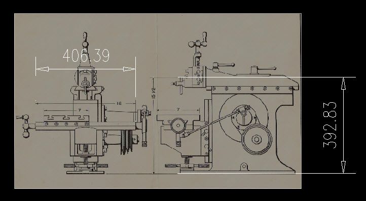
                                                The page has been inserted "Insert menu raster image" as a background. (Just a screen grab from the PDF enlarged to fill the screen) Bigger is better.

                                                Then scaled to fit as metric in Autocad. using the "Scale" command.

                                                Using the table as a reference 16 inches = 406.4mm I got it to within .01 of a mm That L Do!
                                                The z axis not quite as good but within a mm

                                                So the plans were in good condition when they were scanned.
                                                Is anyone interested in building one?

                                                As is? or should we change it….. A Timing belt on the bull wheel maybe.

                                                Regards
                                                John

                                                page one scale check.jpg

                                                Edited By John McNamara on 02/11/2013 06:13:25

                                                Edited By John McNamara on 02/11/2013 06:16:18

                                                #134380
                                                Michael Gilligan
                                                Participant
                                                  @michaelgilligan61133

                                                  Very nicely done, John

                                                  It's way bigger than I have in mind for mine

                                                  But if the plans are that good, they would be easy to scale-down.

                                                  MichaelG.

                                                  #134418
                                                  North Western
                                                  Participant
                                                    @northwestern

                                                    John – looks like a nicely sized machine for model engineering. I have just found these items which may be useful starting points for ideas on mechanical auto lifting of shaper tools, which might interest someone who decides to build the machine, or add to an existing shaper.

                                                    Michael – unfortunately I don’t think they will be applicable in your quest, but may be interesting nevertheless.

                                                    (Note that “Patent” language, US or British, is drafted in a rather unusual style)

                                                    **LINK**

                                                    **LINK**

                                                    Dave

                                                    #134419
                                                    Michael Gilligan
                                                    Participant
                                                      @michaelgilligan61133

                                                      Two excellent finds, Dave

                                                      Thanks for posting the links … very interesting.

                                                      [I'm fairly comfortable with "Patent" language]

                                                      MichaelG.

                                                    Viewing 25 posts - 101 through 125 (of 127 total)
                                                    • Please log in to reply to this topic. Registering is free and easy using the links on the menu at the top of this page.

                                                    Advert

                                                    Latest Replies

                                                    Home Forums Manual machine tools Topics

                                                    Viewing 25 topics - 1 through 25 (of 25 total)
                                                    Viewing 25 topics - 1 through 25 (of 25 total)

                                                    View full reply list.

                                                    Advert

                                                    Newsletter Sign-up