Hope this post/reply is not to long..
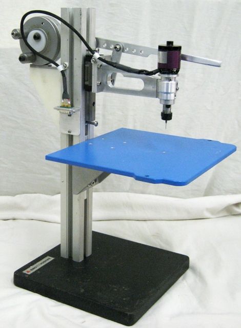
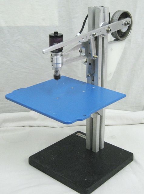
Ian,here are some prior attempts at ways of making up a spindle – I do a fair bit of design on CAD, but sometimes it has to be in the head and in metal..
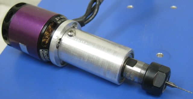
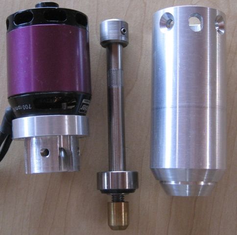
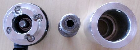
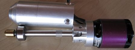
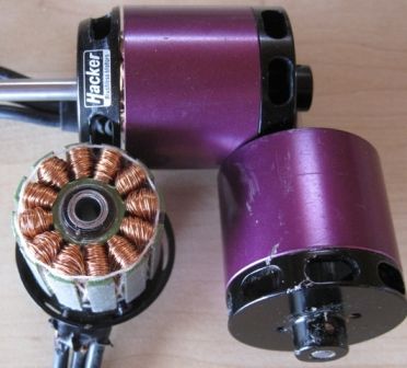
This test spindle shows the HACKER motor fitted with the Ali boss. Also shows the spindle shaft – this one I tried to grub-screw fix the spindle to existing motor shaft – it works, there is very little load on the spindle with the small drills, etc, but there is always some induced runout this way at the coupling, and at 25000 RPM it shows, so, no good. I think you get the idea of construction. I gave up on this idea and went for a full length single chuck shaft/spindle..


Then, your question on how I aligned the bearing/tube at the collet end –
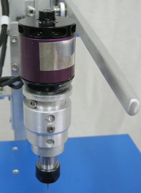
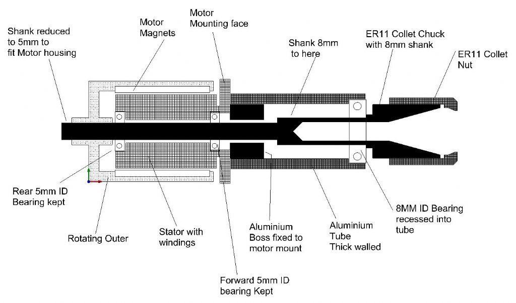
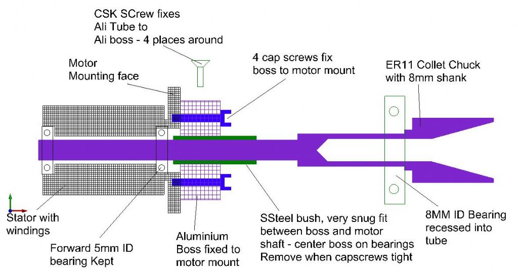
I inserted a very snug fitting SSteel bush between the Ali boss and the motor shaft and fastened the cap screws holding the boss to the motor mount see below-
The collet Chuck was machined down to 5.1mm at the motor end, and then I mounted a piece of SSteel in the lathe collet chuck, and machined a ER11 Male end onto it, so the the Spindle female collet end fitted over accurately. The other end of the collet chuck shaft already had a good center hole. I used a wiggler to check that it was running true with the to ER11's mated tight. I then brought the live center into the dimple in the rear shaft of the spindle, and just tweaked the tailstock up. Check with a dial gauge for parallel and the brought one of the toolpost grinders into service, and gently did it..Worked a treat.

I did not true the taper of the collet after – I could not measure any TIR on my 0.005 indicator..
Here are some more motors, all quite suitable for use in these applications, and even on heftier routers, etc.
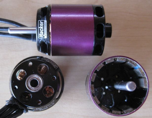
This one is the HACKER, same as I used in the drill – it is 37mm diameter, 42mm long, can take 50amps for 50 seconds, uses 4 amps max on the drill at max RPM. This type of case construction is prefered for a Hi-Speed application – note the cooling 'fan' at the rear – sort of side slots that suck in cooling air. This one is very quiet when running fast – some of the other pics show inlets direct in from the motor rear – these are unbelievably noisy – your ears curl backwards, your eyes water, and your shoulders crunch up….And that high frequency screech goes through ten walls…
The only thing I do not like about these HACKERS are the rather small bearing – 5mm ID x 11mm OD
This motor is about 9 Pounds..(BP)


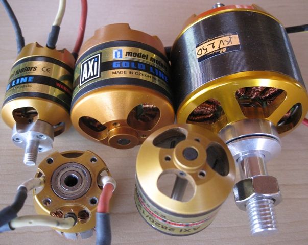
Below AXI ( Czech) Motors, except for the larger one.
The left one is 35mm diam x 45 long, '400watt' – The middle one is 50mmx50mm '950watt' – the Right hand one is 65mm x 60mm long – '2KW' (!) They all have various RPM/Volt ratings (kv).
For a hi-speed drill or engraver application a kv of between 600 and 900 is good. The large motor below is a 250kv, and can be fed from voltages ranging from 16Volts to 80volts – 80 volts would give 20,000RPM – SCARY… Note the larger bearings on the smaller motor – 5MM ID x 16mm OD. This smaller one is an eqivelent of the HACKER I used.

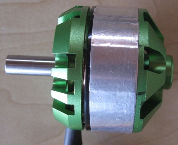
This is a MAYTECH motor, with an 8mm shaft – I used this on my CNC engraver ( see my other postes) – it runs up to 28KRPM no problem – a bit loud as the air is rear entry, but a very nice motor – 50mm Diameter x 40mm long – '600watt' Cost about 11 Pounds..

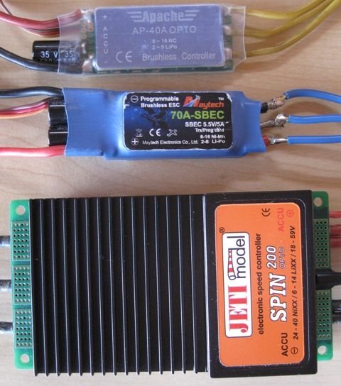
And here are some typical speed controller –
The top one is a 40A 'no-real-name-brand' and it works fine. The next is a 70A, and the biggy is a 200amp…
The 40A one is about 2 Pounds, from any reasonable hobby shop.

Joseph Noci 1.


