Hi All,
Sorry about this. being new to this forum stuff I am still getting my head around how it works. Hope you can see the photos. So, firstly let me say thank you all very much for replying.
However, I am more confused than ever now. I do have a basic understanding of electrics. I did get an ONC in electrical engineering but that was 50?? years ago. And I have worked as an electrician for a year, rewiring houses and stuff. So my knowledge of electrics is mostly of the domestic type. When it comes to 3 phase my knowledge is very limited. And I am well aware that 3 phase will kill you.
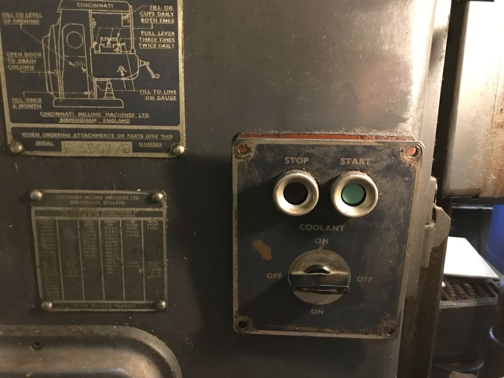
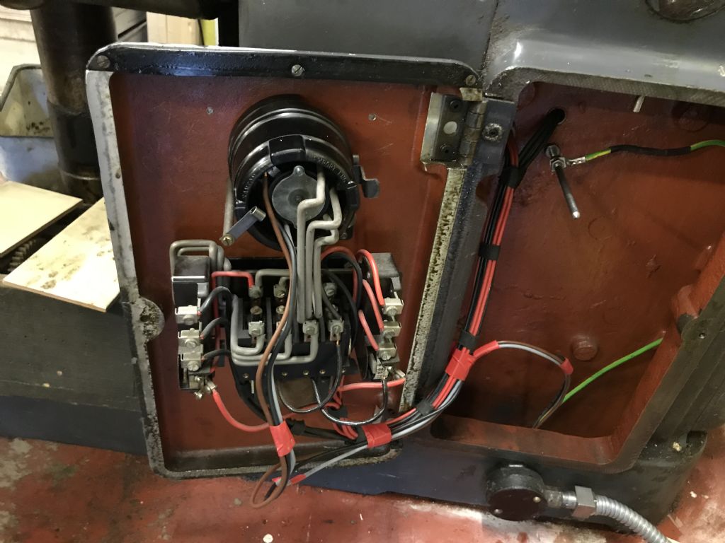
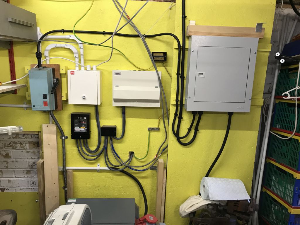
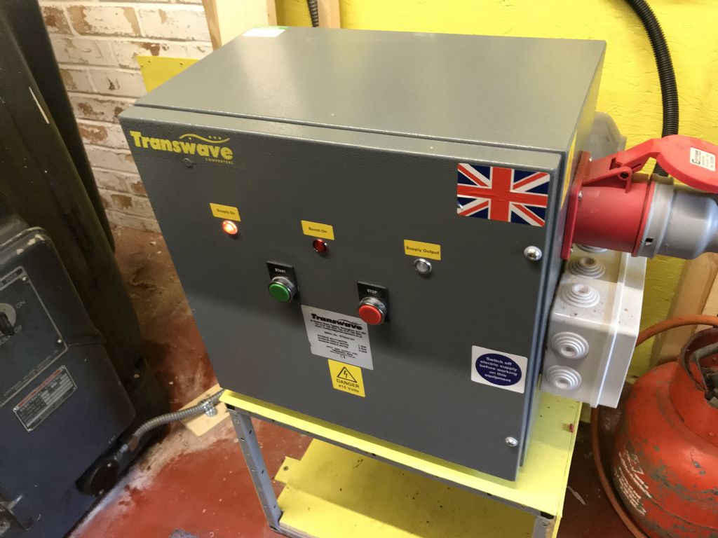
Looking at the photos, going from bottom to top, the first is the Transwave Rotary converter. Then comes the layout of the incoming wiring. The 3 phase distribution board is the large box on the left. The next photo is of the rotary switch on the mill. Then the push button switch and then the inside of the push button switch. Finally a picture of my Cincinnati 2M1 Universal Mill (from the hand book).
The feed to the 3 HP motor on the Lathe is 3 phases plus a neutral. The feed to the 5HP motor on the mill has only the 3 phases, but no neutral. I have measured the potential differences and on the lathe it measures 420, 440 and 460 volts between phases and 240 volts between phases and neutral. On mill the incoming feed measures 420, 440 and 460 between phases.
The isolator for the mill is a Telemecanique and is the one I used in Oxford. As it is the trip on this isolator that keeps tripping I am wondering if it is the correct type to use, but as I said I don't know enough about it. I am thinking now that I need to find an electrician who has experience in this stuff.
Cheers.
Phil Whitley.


