Switch for Myford ML7

Advert

Switch for Myford ML7

Home Forums General Questions Switch for Myford ML7

Viewing 25 posts - 1 through 25 (of 26 total)
  • Author
    Posts
  • #100201
    Charly
    Participant
      @charly

      Me again,

      At the moment I have a straight connection from the motor to the plug, but would obviously prefer to have an on/off switch. Can I buy any type or what should I look out for? There is one going on ebay at the moment.

      Thanks

      Charlene

      Advert
      #22250
      Charly
      Participant
        @charly
        #100206
        Les Jones 1
        Participant
          @lesjones1

          Hi Charlene,
          A switch similar to THIS ONE will provide basic switchin an a no volt release function. (This means the motor will not start up when the lathe is plugged in or after a mains failure.) This type will not provide any overload protection for the motor. For that you need a direct online starter. This must be rated to match the current drawn by the motor. Here is an example of a direct online starter.

          Les.

          #100207
          Charly
          Participant
            @charly

            Thanks Les, I suppose it would be better to get the direct online starter – I guess the overload protection would be there to protect the motor? My motor states 3.7 Amps.

            Charlene

            #100213
            maurice bennie
            Participant
              @mauricebennie99556

              Hi Charlene .Most workshop tools are switched using a device with a "panic " button,I think most people would advize using one ,much safer.

              maurice

              #100220
              Charly
              Participant
                @charly
                Posted by maurice bennie on 07/10/2012 11:48:20:

                Hi Charlene .Most workshop tools are switched using a device with a "panic " button,I think most people would advize using one ,much safer.

                maurice

                Hi Maurice,

                I agree with you totally, but I went and bought a DOL switch and they didn't have any with the big panic buttons, although this one has the stop button protruding, so when I hit it – if I can find it – it should work. I'm just in quite a rush to see and hear how it runs, because I think the motor was bought on the cheap and just thrown in to be able to up the price on the lathe. The lathe is in a bad state, but I will replace the parts as I go along. I just want one to work on for the moment.

                #100221
                Charly
                Participant
                  @charly

                  Hi guys,

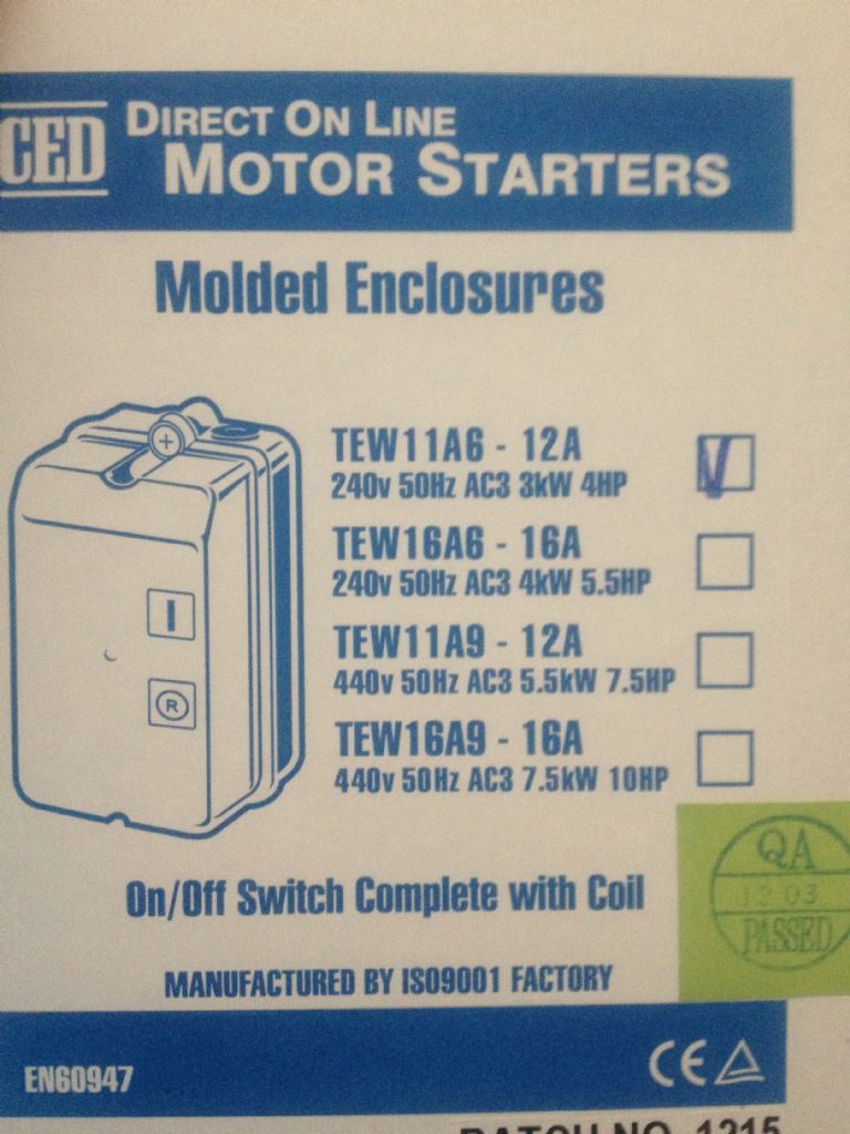
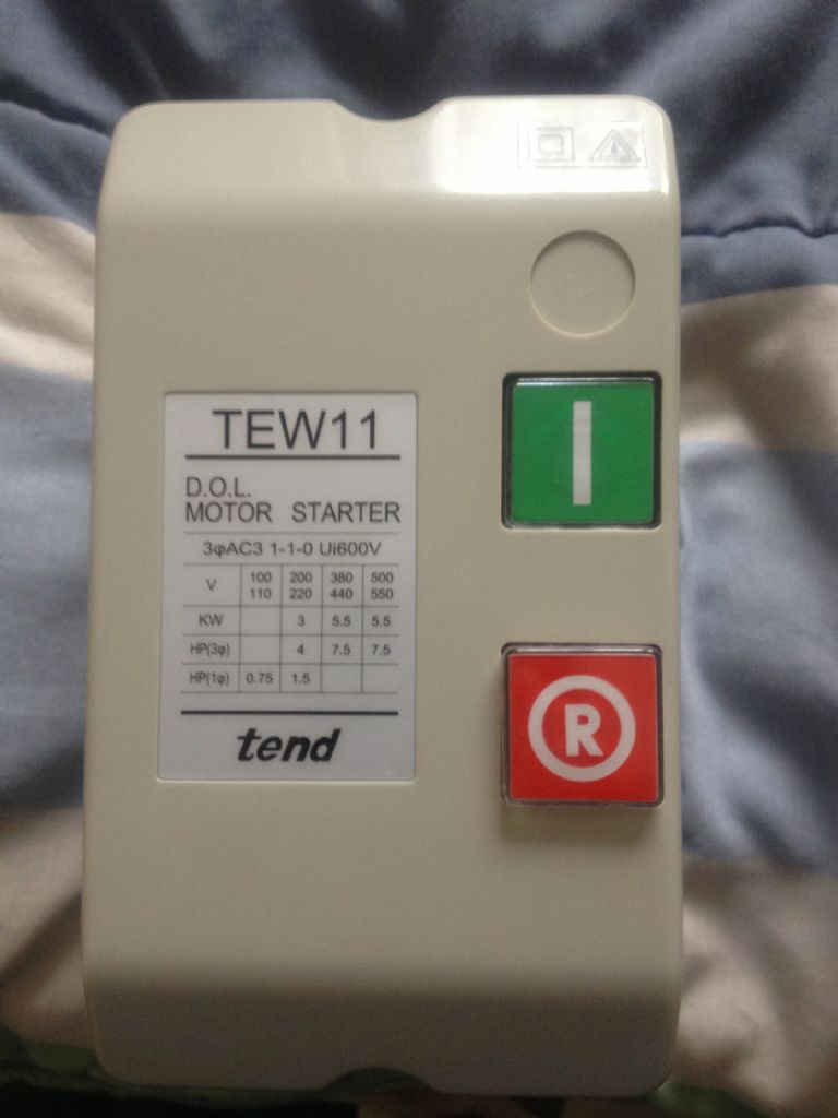
                  This is the switch I got. My motor states 0.5hp and 3.7A, so I reckoned this one should be capable of doing the job. I can go and exchange it if I need to.

                  Charlene

                  013.jpg

                  012.jpg

                  #100237
                  Les Jones 1
                  Participant
                    @lesjones1

                    Hi Charlene,
                    You were quick going out to buy a starter. From the picture it looks like the one you bought is rated at 12 amps. This will not protect your motor. One with 4 or 5 amp rating would be better. It should be possible to fit an external emergency stop button by connecting it in series with the internal stop button. Interlocks on the chuck guard and belt cover can be added in the same way.

                    Note added. While looking for information on the starter in your picture I found that it does not have any thermal overload protection. The company do make thermal overload relays to go with this starter but I do not know if these fit inside the starter or inside a separate box.

                    Les.

                    Edited By Les Jones 1 on 07/10/2012 15:44:39

                    #100246
                    Charly
                    Participant
                      @charly

                      Thanks for that Les. Yes, I had to go and buy some extractors, so I thought while I was at it I might buy one, but unfortunately the wrong one. Maybe I should just order the one in your link from Machine Mart. I think I will do the external emergency stop button as you suggest as well.

                      Charlene

                      #100256
                      NJH
                      Participant
                        @njh

                        Hi Charlene

                        What Les says is quite right but the most important part of the starter is that it is NVR i.e. when the mains go off for any reason the switch trips out and the machine will not start again when the mains are restored. That way you get to keep all your fingers etc. when the power suddenly comes back and you have chosen that time to do the annual clean-up on your lathe. Protection for motor – nice- but penalty for not having it is the price of a new motor should the overload happen. Stop switch ( or to give it a more suitable name – Panic Button.) Big and easily accessible so you can't miss it when all goes pear shaped – yes good idea but you may be very careful of course! It is likely that the starter switch you have can be wired for a remote Stop button- if so just providing a big red "STOP" button in a suitable position and wiring it in might be the cheapest option unless you can change the one you have bought.

                        Cheers

                        Norman

                        Edited By NJH on 07/10/2012 17:55:30

                        #100272
                        Charly
                        Participant
                          @charly

                          Hi Norman,

                          Yes I made sure I could return that starter before I bought it. I have 30 days, so it will go back ASAP. I would take the meaning of NVR to be that it opens the contacts until you physically pull it out again to close it so that power is restored only when you decide it to be?

                          Thanks

                          #100273
                          Mike Poole
                          Participant
                            @mikepoole82104

                            hi Charlene,

                            The starter you have purchased should be suitable for your motor, the overload unit is an optional item and will fit inside the enclosure. Toolstation sell these starters and the overload units, their part number for the overload is 44178 to suit your motor. They also sell mushroom head buttons for remote stops. The stop button on the starter is raised and the start button is flush so a panic fumble for the stop should find it even with out looking. The siteing of the starter should be considered for ease of use and so you will not be in line with the chuck on start up , if the work should leave the chuck for any reason it could hit you. The figures quoted on your starter are the ratings of the contactor and as it is rated up to 4hp is quite ok for a smaller load. The overload is the important item for motor protection and they should be adjusted to suit your motor the unit mentioned has a range from 2.8A to 4.2A and usually they are set to the lower value when you get it out of the box. If not set to 3.7A you may have nuisance tripping. if the overload ever trips do not be tempted to turn up the overload, you either are oveloading the motor or you have a fault, turning up the setting will eventually result in smoke and be expensive.

                            Mike

                            #100274
                            NJH
                            Participant
                              @njh

                              Hi again Charlene

                              I think NVR means " No Volt Release

                              This type of switch is essentially a relay. The "Start" button operates the relay which then holds in via the current flowing through its coil. Another pair of contacts connect the mains supply through to the motor. The supply to the motor is disconnected by disconnecting the supply to the relay coil either by pressing the "Stop" button ( the normal way) or because the mains supply has failed. In either case the relay releases and the circuit path to the motor is broken until the mains is restored AND the "Start" button is again pressed.

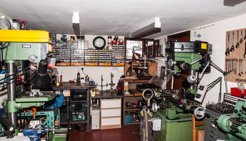
                              You could exchange the starter for one of the correct rating as advised by Les. It is also worth seeing if they can supply a switch with a big "STOP" button built in. They are available – I have one on my mill.

                              You can just see it on the right in this picture – conveniently placed next to my knee when I am working on the machine!  ( Click on photo to enlarge)

                              untitled.jpg

                              Cheers

                              Norman

                              Edited By NJH on 07/10/2012 21:13:08

                              PS. Or go with Mike's suggestion and see if they do a remote "Stop" but this will require wiring etc.

                              Edited By NJH on 07/10/2012 21:18:38

                              Edited By NJH on 07/10/2012 21:21:34

                              #100278
                              Mike Poole
                              Participant
                                @mikepoole82104

                                Hi Charlene/Norman

                                The remote stop for knee or foot operation is a good idea, Colchester had a foot stop/brake on some lathes, very nice to use. A foot stop on a pillar drill I would consider essential especially if like me you don't always bolt the vice down, a jam up can be very difficult to let go of to hit the stop with your hand.

                                Mike

                                #100280
                                Charly
                                Participant
                                  @charly

                                  Hi Michael,

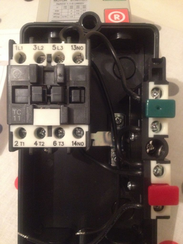
                                  I was going to take that one back, but if you say it will do then I'm glad. I could just go and buy the Thermal Overload Relay extra. I realised the stop button is raised on the box, not sure whether i will still need a remote one then. I will need someone to assist me in the wiring, because the insides don't look like anything I've seen before, lol.

                                  014.jpg

                                  #100301
                                  Les Jones 1
                                  Participant
                                    @lesjones1

                                    Hi Charlene,
                                    Now that Mike has confirmed that the thermal overload unit fits inside the starter I think buying one from Toolstation is the best option. (I had originally assumed that you live in France from your name and the fact that you do not have a profile.) The Toolstation stop button (17283) looks ideal. Don't forget to buy cable glands for where the cable enters the starter and stop button. (Item 25329 on page 390 if you get them from toolstation.) The advantage of this unit over the Machine Mart one is that if you ever need to use it with a different size motor you just need to replace the thermal overload relay. You could just wire it up as it is for now and add the thermal overload and stop button at a later date. (I do not have thermal overloads on my lathe or drill.) It could be argued that as you will always be by the lathe that you would probably notice if the motor slowed down or stopped due to an overload.

                                    Les.

                                    #100313
                                    Cornish Jack
                                    Participant
                                      @cornishjack

                                      NJH –

                                      Norman, totally OT, but where exactly do you do your workshop activities??? Obviously not in that demonstration hall in your photo – or is that your dining room ( eating off the floor, of course!!!)winkcheeky I was teetering on the edge of taking an (out of focus) piccy of my shambles for another current thread but I'm not sure that I shall ever venture into it again. Such exquisite squeaky cleanliness is very disheartening to we mortals!crying 2

                                      Rgds

                                      Bill

                                      #100315
                                      KWIL
                                      Participant
                                        @kwil

                                        It is a Palace of Engineering, not for working in!

                                        #100317
                                        John Stevenson 1
                                        Participant
                                          @johnstevenson1

                                          Best place for on Estop on a milling or drilling machine is forehead hight.

                                          That way when you get dragged in you belt the E stop with your forhead and both hands are free to hold onto whatever is most valuable. smiley

                                          #100319
                                          Charly
                                          Participant
                                            @charly
                                            Posted by KWIL on 08/10/2012 12:36:05:

                                            It is a Palace of Engineering, not for working in!

                                            I agree with that!

                                            Thanks for your input Les. Strange, but this morning while I was having a coffee at work I looked at one of the switch boxes there and the cable gland and couldn't remember what it was called! Thanks for that! Yes, maybe I will leave the thermal overload for now. Should be able to react when I hear the motor is suffering – shouldn't happen to me in any case.

                                            I know it's only 2 or 3 wires, but I have no idea how to wire it up! No instructions with the switch as well.

                                            I will update my profile as well smiley

                                            #100320
                                            Charly
                                            Participant
                                              @charly
                                              Posted by John Stevenson on 08/10/2012 12:47:58:

                                              Best place for on Estop on a milling or drilling machine is forehead hight.

                                              That way when you get dragged in you belt the E stop with your forhead and both hands are free to hold onto whatever is most valuable. smiley

                                              Very good idea John, but unfortunately I don't have that option.

                                              #100322
                                              John Stevenson 1
                                              Participant
                                                @johnstevenson1
                                                Posted by Charly on 08/10/2012 12:55:35:

                                                I know it's only 2 or 3 wires, but I have no idea how to wire it up! No instructions with the switch as well.

                                                I will update my profile as well smiley

                                                No diagram inside the lid ? That's where they often put them.

                                                failing that some decent photos and many here can work the connections out.

                                                Usually simple, L1 and L2 for live and neutral and U &V for the motor leads.

                                                If that doesn't work then use L1 and L3 and U & W

                                                #100323
                                                Mike Poole
                                                Participant
                                                  @mikepoole82104

                                                  Hi Charlene,

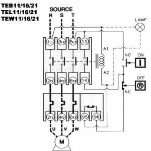
                                                  I have uploaded a diagam of this starter to help my explanation. The diagram shows the 3 phase configuration with overload unit but the single phase version is a small variation. The supply should be connected as follows Live (brown) to 5L3 and Neutral (Blue) to 1L1. Connect the motor live to 6T3 and the neutral to 4T2 on the overload unit, insert a wire from 2T1 to 3L2. Connect the two free wires that have tinned ends to terminals 95 and 96. Check that the thin wire of the two free ends is connected to coil terminal A2. Check or insert a wire from 1L1 to coil terminal A1. The two most important wires are the earths, these must be connected together and an earth point is usually provided in the starter.

                                                  If you do not want the overload unit connect the motor live to 6T3 and the motor neutral to 2T1, the link from 2T1 to 3L2 will not be required remove the thick free ended wire from the red button and insert the free end of the thin free ended wire.

                                                  If you wish to use a remote stop button move the wire that comes from terminal 14 on the contactor from the red button to the bottom of the green button, remove the short link from the red to green buttons and wire the two leads from the remote stop one to the bottom connection of the green button and the other to the top connection of the red button.

                                                  I would advise you to have your handiwork checked by a competant person.

                                                  Mike

                                                  teb1116217.jpg

                                                  #100324
                                                  NJH
                                                  Participant
                                                    @njh

                                                    Well I guess that's you sorted then Charlene -and useful info to file – thanks Mike.

                                                    Kwill and Co. – "It is a Palace of Engineering, not for working in! " Well sorry – it was just a pic I took for the other thread and I used that rather than go out and take one of the starter switch.

                                                    Having managed in several rather pokey, untidy, cold and damp workshops previously and then moving to a place with a double garage I determined to make a dry and comfortable place to "play" in my retirement. I enjoyed the conversion work but, like Topsy, it growed!! If you look at the pic in my album of the other half of the garage then the usual state of my workshop is somewhere between the two!

                                                    My criteria for a workshop is that it must be pleasant to go into, it must be dry and possible to heat economically. Tools must be easily found and, for safety, the space on and around machines must be clear. My interest is in the smaller end of engineering so keeping it fairly tidy also avoids losing bits!

                                                    So Bill post your pictures  it's always interesting to see how others are set up and ideas can often be gained.

                                                    In the end though the important bit is not the workshop but what comes out of it. I make no claim to any great achievement in this area – but I do enjoy trying. ( And in some degree of comfort!)

                                                    Regards to All

                                                    Norman

                                                    Edited By NJH on 08/10/2012 14:02:57

                                                    #100326
                                                    Les Jones 1
                                                    Participant
                                                      @lesjones1

                                                      Hi Charly,
                                                      It is difficult to see from the photograph where the wires at the top go to. Can you confirm (Or correct.) my understanding of the wiring from my interpritation of the picture.

                                                      1 The start button is in parallel with the contacts 13no and 14no

                                                      2 There is a second wire connected to terminal 13no which is one end of the coil.

                                                      3 The wire end in the middle of the bottom of the box is the other end of the coil.

                                                      4 There are no wires connected to terminals 1L1, 3L2, 5L3, 2T1, 4T2 and 6T3

                                                      5 The "T" shaped piece of metal to the right of terminal 14no is not connected to anything.

                                                      ****** IF I HAVE INTERPRETED THE CONNECTIONS CORRECTLY *****

                                                      Connect the incoming neutral to 1L1 and connect the wire that is at the middle bottom of the box to 1L1
                                                      Connect the incoming live to 3L2 and connect the wire from the bottom terminal of the stop button to 3L2 (You may need a longer piece of wire.)

                                                      Connect the motor neutral to 2T1
                                                      Connect the motor live to 4T2

                                                      The "T" shaped metal plate is probably for joining the incoming earth to the motor earth.

                                                      If you are not 100% sure DO NOT PROCEED

                                                      EDIT   I see that Mike has beat me to it with his reply. (I was called for lunch before I finished typing.)
                                                      As Mike's reply contains a diagram it will probably be clearer to follow his instructions.

                                                      Les.

                                                      Edited By Les Jones 1 on 08/10/2012 14:46:53

                                                    Viewing 25 posts - 1 through 25 (of 26 total)
                                                    • Please log in to reply to this topic. Registering is free and easy using the links on the menu at the top of this page.

                                                    Advert

                                                    Latest Replies

                                                    Home Forums General Questions Topics

                                                    Viewing 25 topics - 1 through 25 (of 25 total)
                                                    Viewing 25 topics - 1 through 25 (of 25 total)

                                                    View full reply list.

                                                    Advert

                                                    Newsletter Sign-up