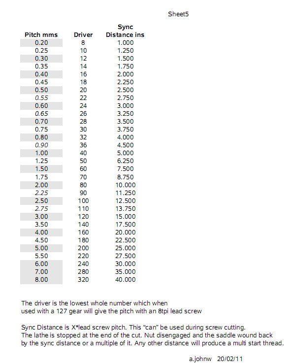
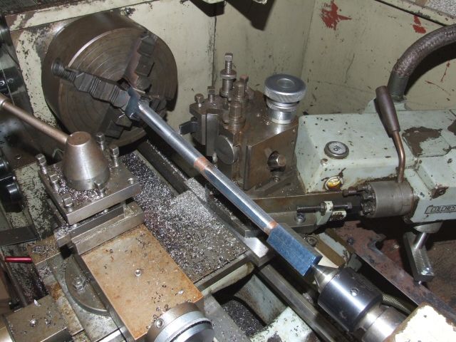
I might be able to explain the screw cutting problem a bit clearer but some thought will be needed as it's best explained via a screw cutting indicator and what this does.
I did have some notes from a lecture that explained the problem via a formulae that initially used radians / second of the lead screw and the lathe spindle but lost them and can't remember anyway. Repeat distances are easier to grasp.
Take an imperial thread on an imperial machine, or metric on a metric machine. The pitch of the thread being cut will divide exactly into so many pitches of the lead screw. That is the repeat distance. The screw cutting indicator has a gear on it which is always engaged with the lead screw. The tooth count on the gear cause the marks on the indicator to always indicate repeat distances as the saddle is moved along the bed. So some thread is cut with the screw cutting indicator at some specific mark. The dial stops turning, at the end of the thread the nut is disengaged and the dial starts spinning again, the saddle is wound back by hand and the spin rate changes but the mark that was used is still in sync with the thread that has been cut so if engaged on that mark again the tool will travel down exactly the same path. I'm skipping the aspect that a number of marks can be used for certain pitches and that the leads screw pitch may be it's own repeat distance for some pitches so it doesn't matter where the nuts are engaged. The indicators are generally positioned so that the nut engage cleanly though so it's always best to use one to avoid the nut riding on top of the lead screw.
So take an odd imperial thread say 7 tpi. The pitch is 0.142857142 ……………. Say the pitch of the lead screw is 0.125. One divided by the other is 0.875. So if the indicator can show repeat distance of 0.875in it can be used. It can also be used if it can shown some exact multiple of 0.875in. I could just arrive at that by dividing the pitch of the thread by the pitch of the lead screw.
The imperial pitches that are used have been picked so that a screw cutting indicator can be used to cut all if not most of them but the indicators capabilities vary from machine to machine. The metric pitches that are used don't follow the same rules so more than one gear is needed for the indicator. Colchester did one with lots of gears but the catch is that at some extremely long repeat interval the marks take a long time to line up so may as well reverse the lathe. It's more normal for metric lathes to come with 1 or 2 indicator gears. 2 is usable on more pitches.
I don't know of a good web page on screw cutting indicator use but there can be other catches. Say a 4 tpi thread is being cut with an 8 tpi lead screw. If screw cutting isn't engaged at the right point it might cut a 2 start 8 tpi thread. Actually that sort of accident happens at times. All goes well and suddenly the lathe cuts the other start. It usually happens when the wanted thread is rather deep.
This all changes when conversion gears are added to cut a thread of the other standard, all down to the number 127 that is needed for exact conversion. There isn't a screw cutting indicator gear tooth count that can be used to obtain a correct repeat interval.  I've never looked to see what would happen if one of them had 127 teeth. Take an example of say a 2mm pitch and a 8tpi lead screw the fraction is 0.078740147………/0.125. It's pretty obvious that the 0.0787…. can't be multiplied by any integer to provide another integer other than n*127. The teeth on the indicator has to be an integer number.
One way of screw cutting without an indicator is to take a cut, stop the lathe and then mark the gears where they mesh together. Then wind the saddle back to the start and run the lathe until the lines mark up exactly again and at that point engage screw cutting again. Waiting for the lines to line up ensures that the lead screw is synced to the thread being cut so it doesn't matter where along it the nut is engaged. The alignment has to be surprisingly accurate for this to work even accounting for the actual angles of the teeth on the gears. This is where using a tumbler reverse is likely to fall down. The gears in it would have to be rather precisely positioned so that they meshed perfectly when changed over. The gears would also need to be identical and engage in the same place on the spindle otherwise there could be an angular error. There are details of a gizmo that does this sort of thing around. It does it by having 2 gears rotating in opposite directions and locations to ensure things remain in sync when the lead screw rotation is reversed. I believe the person who copied that idea from other commercial machines used to have a large handle on the lead screw to wind it back quickly by hand. If the tumbler is used there is no guarantee that it will re engage with the spindle at the same angular relationship as it did before.
The real problem with reversing the lathe and leaving the nut engages is time – it takes a long time for the saddle to get back to the start again, it's also a bit of a problem screw cutting to a shoulder as the lathe needs to stop rather quickly. There is a method of using an indicator to help with that but the lathe is still stopped and reversed. A saddle can be wound back very quickly by hand and working to a shoulder isn't a problem at sensible speeds.
John
–
Edited By John W1 on 24/08/2015 14:31:13
Martin Kyte.


 I've never looked to see what would happen if one of them had 127 teeth. Take an example of say a 2mm pitch and a 8tpi lead screw the fraction is 0.078740147………/0.125. It's pretty obvious that the 0.0787…. can't be multiplied by any integer to provide another integer other than n*127. The teeth on the indicator has to be an integer number.


