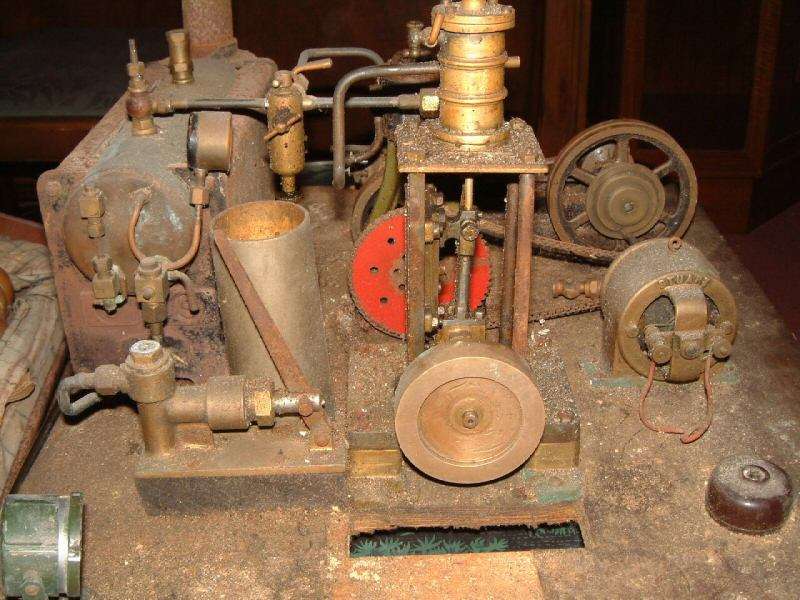
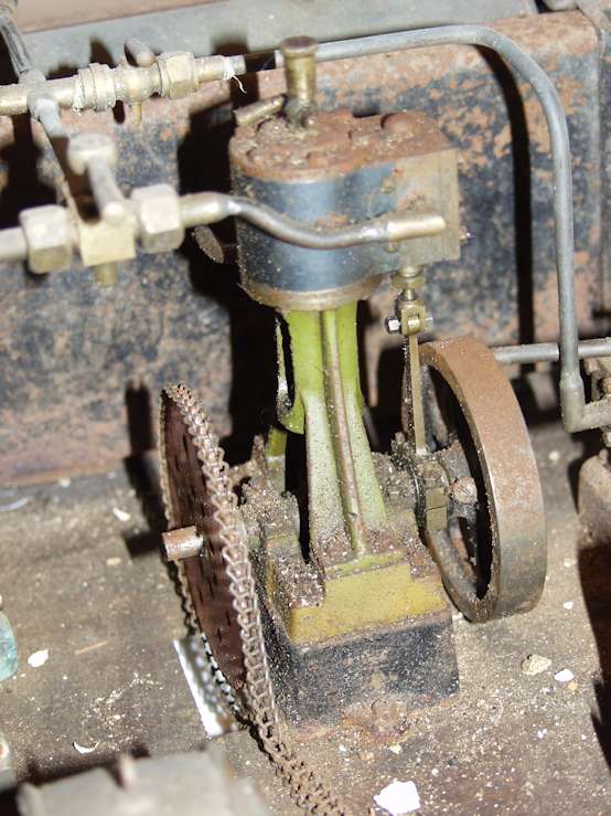
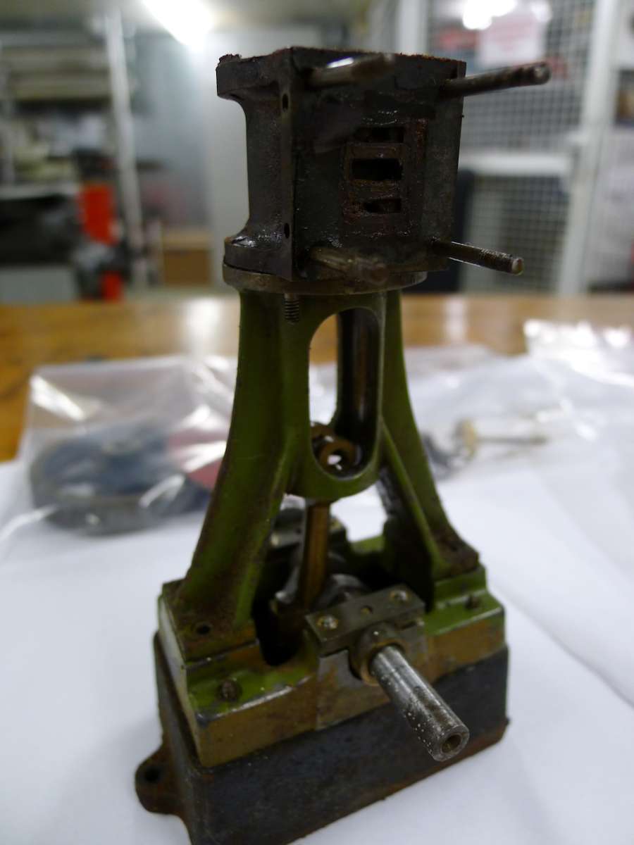
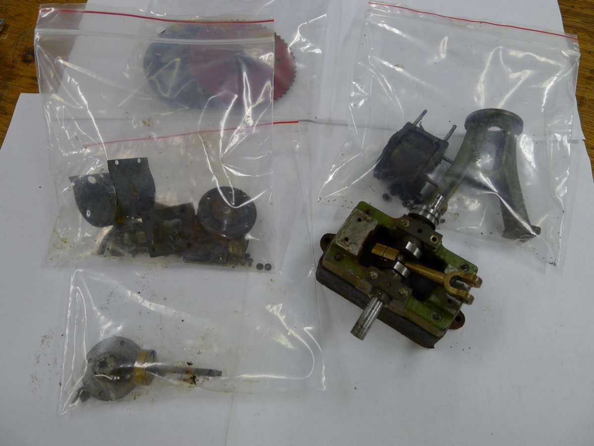
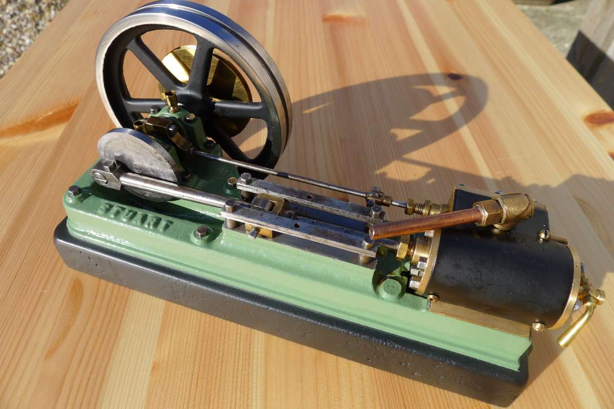
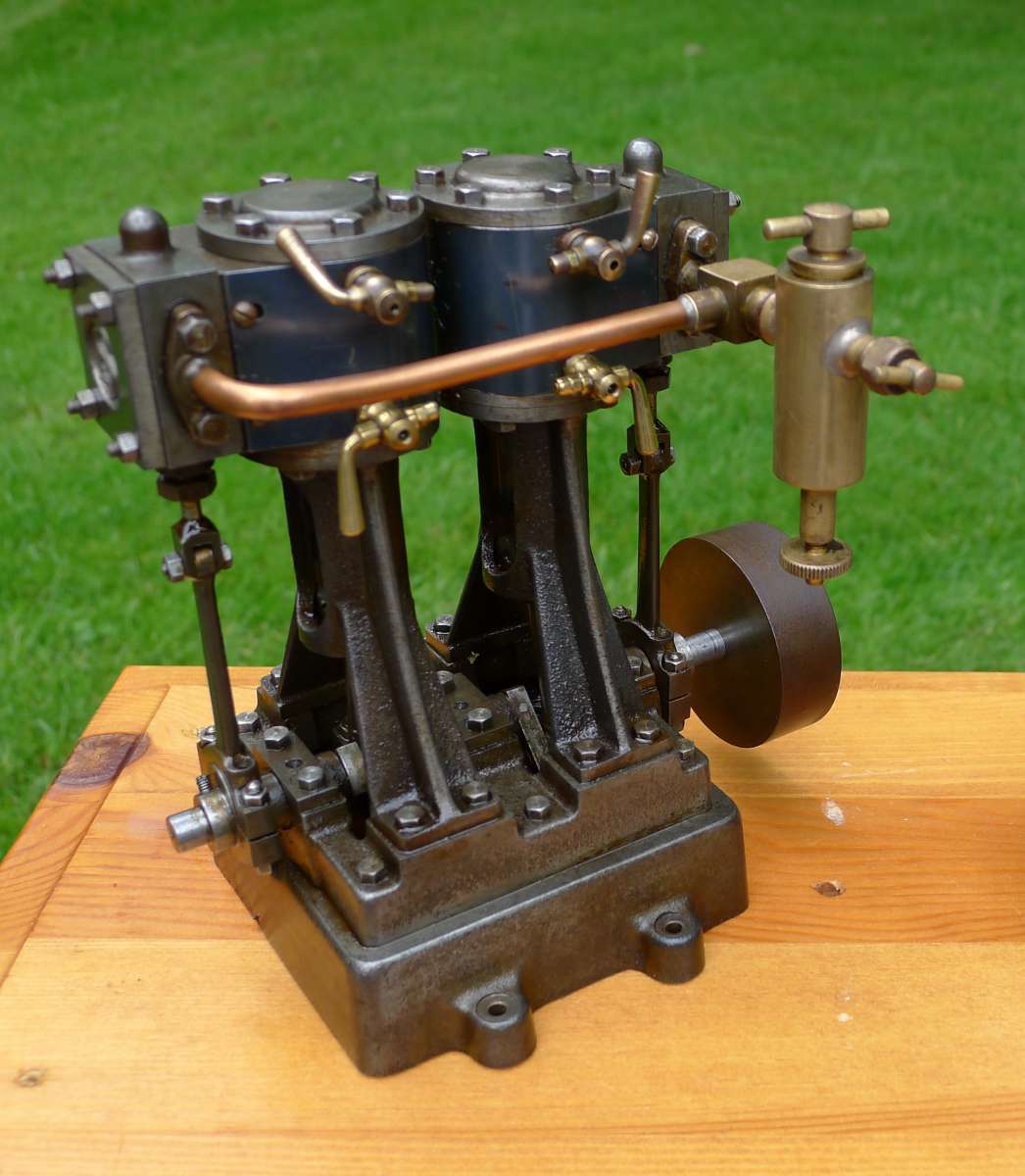
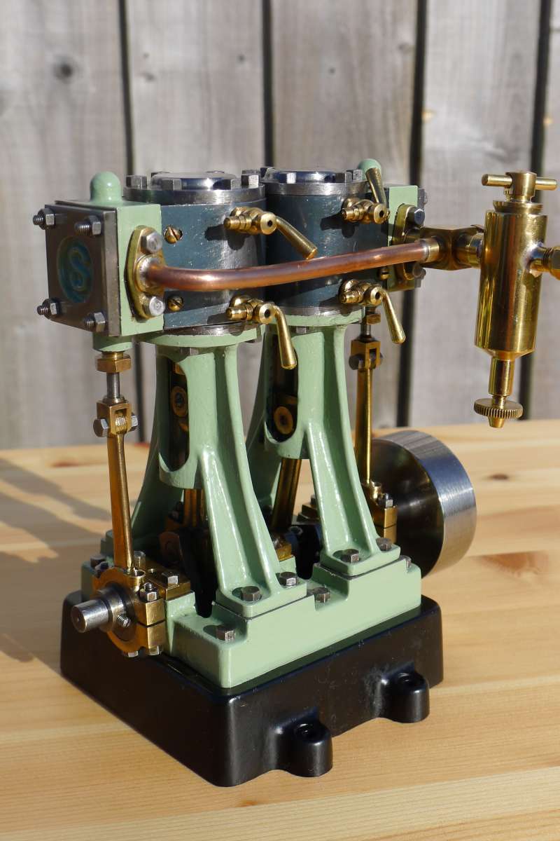
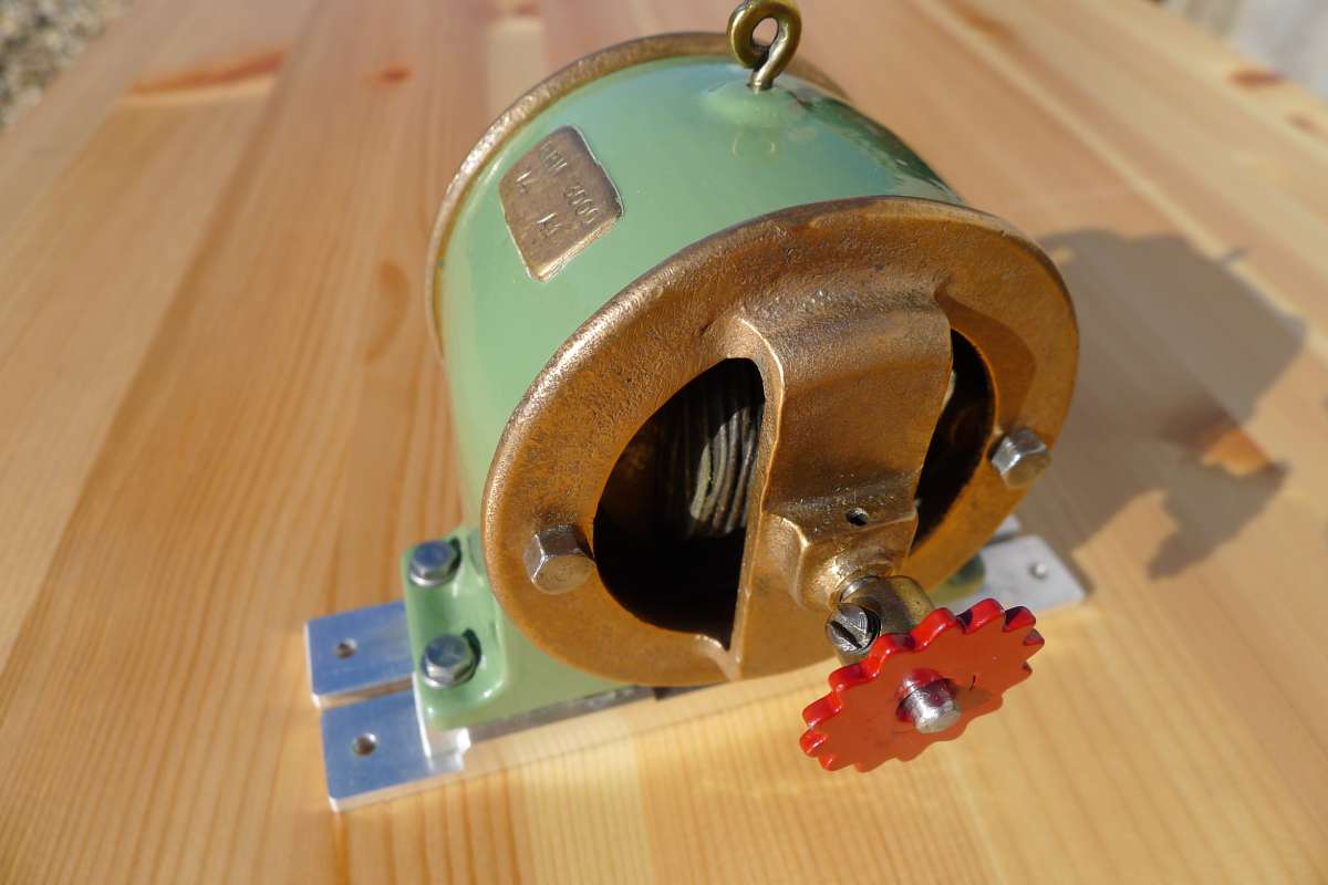
Stuart Restoration

Advert

Stuart Restoration

Home Forums Stationary engines Stuart Restoration

Viewing 18 posts - 1 through 18 (of 18 total)
  • Author
    Posts
  • #811614
    Richard Simpson
    Participant
      @richardsimpson88330

      Although my main interest is model boats I do also dabble with other steam related items such as Stuart Turner engines and plant.  I purchased this item on Ebay around 25 years ago now with the intention of doing a restoration job on it.  When I saw it I started to realise just what I had taken on.  It had sat in an attic for a great many years and my initial thoughts were that it was from around the 1950s or 1960s.  I now know better.  Anyway to kick things off this is what I received when I opened up the box.

      03-03-04-01StuartPlantOriginal1

      DD_3

      EC_3

      F8_3

      4E_3

      8B_3

      001

      Advert
      #811627
      Frank Gorse
      Participant
        @frankgorse

        Just needs a rub with a bit of  Scotchbright Richard. What vintage do you think if not 50s/60s?

        #811631
        Harry Wilkes
        Participant
          @harrywilkes58467

          Nice steam plant good luck with restoration

          H

          #811638
          Richard Simpson
          Participant
            @richardsimpson88330

            Thanks for the comments gents.

            The first engine I decided to have a go at was the 10V, as it looked like the most likely candidate for success.  The process went something along these lines.

            First the strip down.

            01

            Items were bagged according to their grouping so things made a bit more sense when reassembled.


            02

            The running gear was the first bit to be cleaned up.  The right hand bearing is still the original finish but the left hand bearing has been cleaned.  I wanted to aim for a well used but well looked after finish so I wasn’t going for a return to as made but wanted to keep some of the character and finish.

            03

            Eventually, after a lot of work with the Dremel and a wire brush it came out like this.  Luckily the bearings were not too slack so didn’t need replacing or sleeving.

            04

            Other parts were cleaned up ready for painting.  Surfaces were lapped and the painted surfaces taken down to a sound surface.

            05

            Firstly a primer was applied from an automotive rattle can after all mating surfaces had been masked.

            06

            The satin black base was also sprayed but the green was a two part epoxy paint, hand painted on.

            07

            #811639
            Richard Simpson
            Participant
              @richardsimpson88330

              Non painted parts were simply cleaned up with a rotary wire brush in the Dremel and other abrasives and polishes.

              08

              The port face was a bit of a challenge.  To skim it and return it to a perfect finish would have meant removing too much metal.  After cleaning though it was obvious that the surface required dressing up.

              09

              So I decided to lap it to an acceptable standard on a piece of glass with wet and dry abrasive paper taped to it.  It won’t win any competitions for efficiency but I hoped it would run smoothly and reliably

              10

              Starting to rebuild by replacing the running gear onto the bed plate.  The original builder had marked all the bearings so I knew that everything was going back the way it had been originally.

              11

              Followed by the ‘A’ frame and crosshead.  Again there was little noticeable wear in the crosshead so I decided that a clean up was good enough.

              12

              The old solid gland packing material was removed from the piston grooves and neoprene piston rings were made in the lathe.  The glands were packed with graphite string and new gaskets made out of chart paper.

              13

              The cylinder was refitted so the valve could be centralised and timed.

              14

              And finally the covers were refitted.  The engine was run on compressed air and it ran extremely smoothly on very little air so I was very pleased.  So that was the first engine.

              15

              There is a YouTube clip of it running here:

              #811640
              Richard Simpson
              Participant
                @richardsimpson88330
                On Frank Gorse Said:

                Just needs a rub with a bit of  Scotchbright Richard. What vintage do you think if not 50s/60s?

                Frank, I’ll explain in detail when I get to the boiler refurb but I now know it is circa 1920s.

                #811650
                JasonB
                Moderator
                  @jasonb

                  That has cleaned up well.


                  The “A” framed 10V was not introduced until 1933, before that the “10” had a single cast standard and turned support much like a miniature No 1 so maybe the whole plant was assembled with items of various vintages if you have something from the 20s.

                  The threads used can also help age an engine, early ones would have used Whitworth and later BA.

                  #811652
                  Richard Simpson
                  Participant
                    @richardsimpson88330

                    I won’t go into the same level of detail with the other components as I did with the 10V as it was all pretty much the same.  The next engine for the treatment was the horizontal S50 engine.  This was stripped, cleaned up, rejointed and resealed and reassembled.  The slide valve was noticeably sloppy on this engine so a shim was made up to sit between the square nut and the rear of the slide valve to remove some of the excessive slack.  Again the engine ran very smoothly and slowly when run on compressed air.

                    01

                    The last engine was a bit of a challenge.  It was an unidentifiable home made engine but was not made particularly well.  The running gear was sloppy and it simply didn’t fit with the rest of the plant.  I decided to replace it with another Stuart engine and was lucky to find a D10 in complete but unpainted condition.

                    02

                    This was stripped down, cleaned up and checked out and finished the same as the other two engines.  Luckily there was very little adjustment to make to the steam manifold to make it fit.

                    03

                    One thing I particularly wanted to do was to make the dynamo work again.  It was stripped, cleaned and painted up before testing it in a lathe.  I couldn’t get it to produce any electrical energy initially so this was going to require further investigation later.  The dynamo was mounted on two runners to allow lateral movement when it was screwed to the base.  This meant that the chain could be tensioned by slackening a couple of pinch bolts thereby removing the need to re-screw the dynamo into the base at different positions.

                    04

                    The boiler was also odd as I noticed that the fittings were screwed directly into threaded holes in the end plate.  Stuart Turner were adamant that they had never produced such an arrangement so I assumed it had been either messed around with or it was a manufacturing fault.  I therefore made my own bushes and fitted them.  When I mentioned it on a different forum a member there informed me that this arrangement was produced on Stuart Turner 500 boilers in the 1920s.  This therefore dated my plant around 30 years older than I had originally thought.  Sadly now the boiler is no longer as original but that’s not the end of the world for this project.

                    05

                    The side plates had the old asbestos based insulation removed and ceramic cloth glued on to them instead.  The fittings were all cleaned up with a rotary wire brush in a Dremel.  The end plates were sprayed matt black and the side plates were sprayed gloss black for no other reason than I like the contrast.  The shell was cleaned up and pickled internally before a test dry assembly.

                    06

                    When I was happy that everything was OK it was taken apart again and the shell was polished up.

                    07

                    I decided then to do a dry assembly of the main components on a new baseboard that I had made just to see how everything went together.  The steam manifold was left as it was but cleaned up.  Everything seemed to go together as I’d hoped.  I’d even managed to get my hands on an original single poker burner so the boiler could be fired by meths as per original.

                    08

                    #811653
                    Richard Simpson
                    Participant
                      @richardsimpson88330

                      The plant sat on a shelf in that condition for a few more years until recently, when a fresh injection of enthusiasm led me to get it out again.  It was time to get this project finished.  The first job was to finish the baseboard, get things permanently fixed down and give things a run.  Most plant like this seem to be finished with black and white floor tiling so I wanted something a little different.  I fancied the idea of wooden floor boards so turned to my stock of doll’s house wooden flooring that I use a lot in model boat construction.  I played around with some washes and was happy that it would look good.  The floor was laid, painted with some enamel washes, distressed with Scotch Brite pads and given a couple of coats of matt polyurethane varnish.

                      The three engines and the boiler were then all fixed to the base with inverted allen cap head screws sunk into the base from underneath.  Nyloc nuts were fitted to the top side.  The manifold was fitted up to everything and a large volume of meths was purchased.

                      The first run proved one thing above all else, the exhaust steam was only ever going to make a mess of everything so an exhaust manifold and a separator was obviously going to be needed.  Luckily I had a spare separator in my drawer so I set about making an exhaust manifold.  This required bespoke adaptors to be made to convert varying thread types to enable a modern 3/16th system of fittings to be used in the pipe.  The separator was also fixed to the base, neatly alongside the S50 engine, which allowed a neat arrangement of an exhaust manifold from the three engines.

                      The tank

                      09

                      and the new exhaust manifold.

                      10

                      With the engine side out of the way I still had the feed system to refit so a new set of pipe work was made to fit the pump to a new copper feed tank and the boiler inlet valve.

                      11


                      #811655
                      Richard Simpson
                      Participant
                        @richardsimpson88330

                        A number of test runs required the S50 to be removed for a couple of little jobs to be done and the dynamo output was tracked down to a weak permanent magnet.  A new one was purchased from Stuart and, for the first time in probably may years, the dynamo produced power.    I was lucky enough to come across a nice brass lamp recently, which was earmarked for this project and i found a simple single pole switch to operate it.  I removed the old bulb and replaced it with a new LED lamp.  A number of runs on steam now gave me an operational lamp again, which, I strongly suspect, fulfils the original purpose of the plant, which would have been as an educational toy.

                        Further steam test proved one thing, the D10 and the 10V worked perfectly on steam but the S50 would not.  Various different tests confirmed that it worked perfectly on compressed air, so I believe the engine is OK, but it locks up when steam is supplied.  I suspect the quality of the steam from the boiler is so low that it very readily recondenses in the steam manifold and collects in the low part of the manifold just before the S50.    This will be addressed at a later date but meanwhile what to do for now would be the question.  As the main aim had been to get the plant ready to present at the Yeller Belly Steam Show this year, a charity steam toy show in Horncastle, I really didn’t want the added concern of using a large meths burner so I had already decided that it would be displayed using compressed air.  As I had already earmarked a couple of figures to bring a bit of life to the plant I decided that one could be working at a workbench with a large valve sat on it as though being maintained.  This valve is simply a replacement fitting for the safety valve on the boiler, which then allows a compressor to be directly connected up to the boiler.  I scratch built a work bench with a cradle for the valve and made up a bespoke valve for the air line.  Basically is is somewhere to keep the valve and prevent it from getting lost.

                        Painting up the figures, adding handrails and all the other bits and pieces of detail finally finished off the plant ready for November.  The three engines run beautifully on compressed air and the lamp over the work bench comes on with the switch.  I’m a happy teddy.

                        Final pictures.

                        Fred at his workbench looking after the air valve.

                        P1110490

                        The dynamo, producing power again.

                        P1110491

                        Fred’s mate Albert leaning on his shovel while keeping an eye on things.  These are of course the days before health and safety when everything moving would need to be enclosed!

                        P1110492

                        The S50 with the separator tank sat alongside it.

                        P1110493

                        Over the S50 to the 10V.  Note all the steam manifold was also lagged with string.

                        P1110494

                        Access to the meths burner.

                        P1110496

                        The new copper feed tank and the Stuart Turner feed pump.

                        P1110500

                        The D10 from the other side.

                        P1110501

                        Finally an overview.

                        P1110508

                        #811656
                        JasonB
                        Moderator
                          @jasonb

                          Is it a 500 or 501 boiler? The early 500 boilers did not have a water gauge, just a pair of try cocks.

                          How many tubes are there under the boiler barrel?

                          #811668
                          SillyOldDuffer
                          Moderator
                            @sillyoldduffer

                            Excellent, just what I like with my breakfast coffee.  Hard to date, could have been made almost any time in the 20th Century because Stuart have been going for donkeys years.  Ditto Meccano, who provided the chain and sprocket wheels.

                            May I suggest three minor improvements, replacing parts out of character with the rest.  Nothing difficult, and they offend my eye!

                            improvements

                            The switch at arrow ‘A’ is clearly designed for human fingers, and its scale is wrong for the model.  And the d*mn thing being bright and shiny catches the eye.    Nothing that size and shape existed in an engine house!  Could be hidden round the back or replaced with a simple home-made brass knife switch scaled to match the man.

                            The plastic twin cable connected to the dynamo is also a bit out of place, though only a pendant might notice!   First, wiring is never run at anything other than a right-angle, so drop it straight down to a new hole in the floor.   Second, plastic insulated wire could be replaced with shiny brass strip or thick copper wire.   Both look more like the open busbars found in early electrical installations, and would match the look of the steam installation.

                            The way the dynamo is fixed to the floor looks odd to me.  No Aluminium in early engine rooms!   The sticky out feet are unnecessary and the mounting seems over-complicated.  Might be a poor implementation – an old dynamo I saw in Wales had a similar arrangement, except it the slim Aluminium in the model was replaced by a hefty balk of timber, a good way of reducing vibration on the cheap.  I’d be happier if the model dynamo were bolted straight to the floor, or the Aluminium was disappeared by painting it black!

                            Sorry to be a fuss-pot, but minor anachronisms stand out in a first-class job!

                            OMG, I’ve turned into Inspector Meticulous.  Nurse, where’s my medication…

                            🙂

                            Dave


                            #811670
                            Richard Simpson
                            Participant
                              @richardsimpson88330

                              The dynamo is mounted like that because it is free to slide to ensure the perfect chain tension.  The unit is then locked in place by two screws underneath the unit.  The cable is mounted at an angle to give a little flexibility to accommodate movement of the dynamo.

                              My apologies for offending your eye, it wasn’t my intention.

                              #811680
                              Richard Simpson
                              Participant
                                @richardsimpson88330
                                On JasonB Said:

                                Is it a 500 or 501 boiler? The early 500 boilers did not have a water gauge, just a pair of try cocks.

                                How many tubes are there under the boiler barrel?

                                I was reliably informed that when they were first introduced the 1920s, that Stuart 500 boilers only were not fitted with mounting bushes but the fittings were screwed directly to the threaded end shell.  The larger boilers used normal bronze mountings.  After a few years the 500 boiler also reverted to using bronze mountings.  I have now come across one other example of a Stuart 500 boiler which also has fittings screwed directly into the end plate.

                                Its all a bit irrelevant now as I’ve fitted my own bushes and hence rendered the boiler non standard, but that was as a result of Stuart informing me that they never built boilers without bushes.

                                #811686
                                JasonB
                                Moderator
                                  @jasonb

                                  I’m more of an engine man than boiler as I like to recreate the obsolete and obscure engines from the likes of Stuart, Bassett-lowke, Gammages, etc. I think the 500 with just try cocks screwed them into the plate but not 100% sure if the first ones with water glasses did or not. The 10V is certainly 1933 at the earliest.

                                  The way you have mounted the dynamo is perfectly period correct so can’t agree with Dave about bits sticking out. Infact some of the other suppliers of model dynamos provide similar adjustable mountings as an extra.

                                  #811700
                                  Colin Bishop
                                  Moderator
                                    @colinbishop34627

                                    I think Dave is being a bit picky really As MB Forum moderator I suggested Richard share his work on here as it would be of interest to ME members. Just to give a bit of background, Richard is a superb model maker as well as an expert in model marine steam and his modelling interests include model railways including building scenery. He can turn his hand to most model making and model engineering subjects, always to a high standard as befits his professional background.

                                    He is also an expert in restoring classic motorcycles and his day job until not too long ago was Chief Engineer of an 85,0000 ton cruise ship for a major cruise line.

                                    The latest issue of Model Boats includes his 166th regular article on model marine steam and associated subjects and he has contributed many other modelling articles over the years, particularly with regard to weathering effects on scale models. A pretty impressive CV really and one I doubt if many others on these forums could match.

                                    Colin

                                    #811718
                                    bernard towers
                                    Participant
                                      @bernardtowers37738

                                      Well done nice job its far too easy to go down the picking holes route.

                                      #811730
                                      JasonB
                                      Moderator
                                        @jasonb

                                        Did seem a bit odd to just pick out the bare aluminium as incorrect when there is a whacking great copper boiler and feed water container but that did not seem to be a nit to pick.

                                        The dynamos do need to be run at a fair lick to get something out of them, you have a reasonable ratio with the size of the drive sprocket so the engine should not need to be run too fast, you want about 3000rpm at the dynamo. The amount of steam the boiler can produce will likely be the governing factor at least for prolonged running. My 10V will run quite a few LEDs off a compressor

                                        The table engine could still be improved and treated as a separate project. The cylinder has the looks of one from Stevens’s Model Dockyard with it’s twin bands. the remaining barstock parts like entablature, columns and base could with a bit of work and some paint be made to look a lot more like castings and then it would just need a spoked flywheel in place of the disc one which is completely out of keeping on that engine, it would be more appropriate on the 10V.

                                      Viewing 18 posts - 1 through 18 (of 18 total)
                                      • Please log in to reply to this topic. Registering is free and easy using the links on the menu at the top of this page.

                                      Advert

                                      Latest Replies

                                      Home Forums Stationary engines Topics

                                      Viewing 25 topics - 1 through 25 (of 25 total)
                                      Viewing 25 topics - 1 through 25 (of 25 total)

                                      View full reply list.

                                      Advert

                                      Newsletter Sign-up