Myford ML4 Restoration: Headstock bearings and spindle removal

Advert

Myford ML4 Restoration: Headstock bearings and spindle removal

Home Forums Manual machine tools Myford ML4 Restoration: Headstock bearings and spindle removal

Viewing 25 posts - 51 through 75 (of 123 total)
  • Author
    Posts
  • #469111
    Howard Lewis
    Participant
      @howardlewis46836

      For what my advice is worth, I am fully in agreement with Brian about holding a close clearance on chuck registers.

      In the case of a 3 Jaw chuck, it will have some eccentricity anyway. There seems absolutely no sense in having a slack fit between chuck and mandrel, to make matters worse.. If you have that, you will have no idea what run out there is each time that you fit, or maybe, even, use the chuck. That will make holding diamters concentric more difficult. And if you are merely trying to take a skim to clean up, will require a deeper cut, which could be more metal than you want to remove.

      A 4 jaw chuck will allow you to compensate for any eccentricity of the chuck, but why make extra work, for no good reason?

      Howard

      Edited By Howard Lewis on 04/05/2020 18:27:10

      Advert
      #469130
      david bennett 8
      Participant
        @davidbennett8

        The subject of nose registry has been done to death on many other sites. Don't forget the nose thread is an inclined plane, and together with an accurate abutment face acts similarly to a nose taper. I suggest we ask the original poster to try an ml7 3 jaw chuck before modifying the lathe nose and let us know if it repeats well.

        Dave

        #469142
        Luke Mitchell
        Participant
          @lukemitchell30627

          Hi all,

          I've just taken some measurements and the gap between my ways is 20.2mm. This is considerably less than the 35mm that you mention, Brian.

          Jon, does that couple with measurements for your machine?

          Posted by david bennett 8 on 04/05/2020 19:49:01:

          The subject of nose registry has been done to death on many other sites. Don't forget the nose thread is an inclined plane, and together with an accurate abutment face acts similarly to a nose taper. I suggest we ask the original poster to try an ml7 3 jaw chuck before modifying the lathe nose and let us know if it repeats well.

          Dave

          If I purchase or come across a chuck with an ML7 backplate, which is quite likely if I can't improve upon my existing selection, I will try it as-is and take some measurements. For science.

          I am inclined, however, to make the modification. It seems the more trustworthy option and, to boot, the change is not a permanent one and so the ML4 can be restored to it's original state if necessary (although this may well be difficult if the fit is good enough!).

          Cheers

          #469156
          Jon Cameron
          Participant
            @joncameron26580

            Hello,

            2nd attempt at a.(shortened) reply, Luke, I'll get measuring the steady and sharpen my pencil. It should be possible to build it up and machine it back from bar stock.

            I actually came across this thread by accident, though glad I did as hopefully I can repay some of the help I recieved when I started with mine.

            I never did make an adaptor.for the spindle nose as been a poorper machinist the cost of buying new 3 and 4jaw chucks, and faceplate ect. Wasn't viable at the time, however as tooling increases the more I have bought that needs the 1.1/8" thread. The lathe came with plenty of tooling already threaded 7/8" 9TPI so I have kept it as it was.

            There is a lot of issues that has prompted my lathe been pulled apart, the main one was the motor running hot. There was a knocking from the layshaft, (not a myford one), on stripping down the motor pulley has never been keyed and had come loose on the shaft, also the bearings for the layshaft (they look like brass) have worn oval so combined it was making a heck of a racket. Theres a few other issues that I'll be sorting out. Plus now i have garage instead of the 6×4' shed. So there was another reason to strip it down, I have room to do bigger projects.

            If I can be of any assistance just ask.

            #469159
            Jon Cameron
            Participant
              @joncameron26580

              Luke, the first reply I posted detailed the bed. Mine measured 25mm between the ways and is raw cast. 75mm over the bed ways.

              #469174
              Howard Lewis
              Participant
                @howardlewis46836

                From what I have seen of the M types, the official steady would probably clamp across the dovetail bed.

                For one ML4 owner, I made a Saddle Stop which did this.

                So, possibly, it may be possible to make a fixture to clamp to the dovetail, and have a steady fixed to its top?

                Just a thought

                Howard

                #469184
                Jon Cameron
                Participant
                  @joncameron26580

                  Howard the original fixed steady for the ML1,2,3&4, has a flat soleplate, and a 1/8" plate, to a 3/8" BSF bolt which pulled the steady into the ways. It should be possible to build one up (although not as ornate) from 20x100mm plate, around 150mm off, some 5 or 6mm x 40mm plate, around and some 1/2" steel round. Either bolted or preferably welded before been machined down. The ML10 and M-type lathe both utilised the dovetail ways to locate onto the bed.

                  Luke is the second person now owning an ML4 that wishes to have a fixed steady, so would be practical for me to measure and do a set of drawings so they could be used to fabricated up.

                  #469192
                  david bennett 8
                  Participant
                    @davidbennett8

                    Luke thanks in advance for your future efforts for science!.The ideal time to try this is when you

                    are trueing your new backplate to your lathe. When it is true,de-mount the backplate, then try to re-mount it off centre.Let us know if you can.

                    Dave.

                    #469266
                    Brian Wood
                    Participant
                      @brianwood45127

                      Gentlemen,

                      I live and learn along with you. Dad's ML4 had a machined gap running down the centre of the bedways, I made my 4 arm steady using that as the locator to keep it at right angles to the lathe centreline.

                      With my present lathe, the ML7R and it's predecessor the ML7, this big steady fitted that gap of 35 mm precisely so in my ignorance I assumed the earlier ML4s were also machined and to that dimension.

                      Clearly I have something to learn from this aspect although I would just add that the accessories section in Dad's handbook shows a three arm steady [and rather crude it was too with round steel fingers] located from the gap between the bedways, not across them.

                      Kind regards to all Brian

                      #469281
                      Jon Cameron
                      Participant
                        @joncameron26580

                        Hi Brian, I must admit that having the centre section machined would be advantageous for setting up tooling such as a fixed steady, it would have also eliminated the cost of having the adaptor plate made for the alomco milling attachment. hey ho.

                        Perhaps the centre section was machined at a later date, or requested when your father bought the lathe from myford.

                        The steady you describe is what I have with the three fingers around the bore, with the top piece pivoted so it can be opened to retrieve the work piece. I have some of the steel mentioned earlier so if I can get the drawing finished and ledgible, (i'm no draftsman, but try my best), I will make a start on welding the bits together to build up the base, and pivot. Having a think on machining it last night. it will all be able to be machined on the faceplate, utilising an angle plate or packed up on the cross slide for drilling the hole in the base, (a little less precarious), with less overhang from the faceplate.

                        Jon

                        #469317
                        Brian Wood
                        Participant
                          @brianwood45127

                          Hello Jon,

                          Considering I would have been maybe 5 or 6 years old when Dad ordered his lathe, I can't be sure if he asked for the gap in the bedways to be machined. I rather doubt it though, I am pretty sure that is how it was supplied at the time. Certainly it was never machined later.

                          He also had to convince the pen pushers in the Ministry of Supply to issue him with a wartime Machine Tool Licence to be able to buy it in the first place. The excuse was that he needed it to be able to re-machine cast tungsten carbide glazing cylinders used in his leather factory to put a shine on the finished product, while at the same time bringing out the final colour from the previous matt finish. And as we all know of course, grinding is the only way of coping with that requirement, not with a lightweight lathe. ..

                          With the pretty well complete absence of any kind of understanding by the civil servants of mechanical matters [much like today really, little changes] the license was granted, the machine and accessories were ordered BUT it was delivered to our home, a flat adjacent—it never went into the factory!! He was always rather proud of the con he had pulled.

                          Kind regards Brian

                          Edited By Brian Wood on 05/05/2020 11:34:24

                          #469364
                          Jon Cameron
                          Participant
                            @joncameron26580

                            Hi Brian, I've heard of stories of men having to swindle the system to be able to buy a lathe and other tools after the war time years. There was little resources and the idea of buying a lathe for pleasure, instead of using it to get Britain back on its feet, well…… Its does make me smile of Curly tucked away in a bunker machining away on his little lathe. Bits of scrap, that he turned into loco's, and even simple toys for the young enthusiast. Then retiring to the house to respond to letters and write articles for ME.

                            His garden railway was very nearly blown to bits at one point, been adjacent to a main line. I'll leave it there as its slightly off topic for this thread, but always amuses me.

                            #469365
                            Jon Cameron
                            Participant
                              @joncameron26580

                              Hi Brian, I've heard of stories of men having to swindle the system to be able to buy a lathe and other tools after the war time years. There was little resources and the idea of buying a lathe for pleasure, instead of using it to get Britain back on its feet, well…… Its does make me smile of Curly tucked away in a bunker machining away on his little lathe. Bits of scrap, that he turned into loco's, and even simple toys for the young enthusiast. Then retiring to the house to respond to letters and write articles for ME.

                              His garden railway was very nearly blown to bits at one point, been adjacent to a main line. I'll leave it there as its slightly off topic for this thread, but always amuses me.

                              #469392
                              Michael Gilligan
                              Participant
                                @michaelgilligan61133

                                Intrigued by this discussion about the Fixed Steady …

                                I was surprised and delighted to find this: **LINK**

                                http://vintagemachinery.org/pubs/4654/6592.pdf

                                Accessories MA-62 and MA-62a being relevant, and presumably identical except for their centre heights.

                                MichaelG.

                                #469413
                                Brian Wood
                                Participant
                                  @brianwood45127

                                  Hello Michael,

                                  Yes indeed, those were the ones. As I said further back in the thread, the fixed steady was located by the guide block that fitted the space between the bed ways. My Dad's lathe, the ML4 he bought in 1945, came with this feature machined. Both Luke and Jon have what sounds like they have cast finishes to theirs.

                                  The fixed steady was rather crude, the fingers were in steel bar, perhaps 1/4 inch diameter, with no concession to avoid marking the work and the travelling steady support feature was merely a piece of notched out flat steel bar. I know this was in wartime and maybe the best that could be done for the price, but even as a kid I thought these were crude pieces. Other things were much better finished. Even the 25 T gear on the spindle was stamped with the machine serial number as well as the spindle…

                                  Well found

                                  Kind regards Brian

                                  #469473
                                  Jon Cameron
                                  Participant
                                    @joncameron26580

                                    Now then Michael, that's intruging indeed!!! I'd seen that publishing once already but hadn't paid attention to the myford part number. What year was that sales magazine published??? The fixed steady I have is M47, which predates those part numbers, plus mine was in Myford colours, though in my opinion poorly machined. As Brian says it has crude 1/4" steel fingers with not a lot of regard to the surface finish.

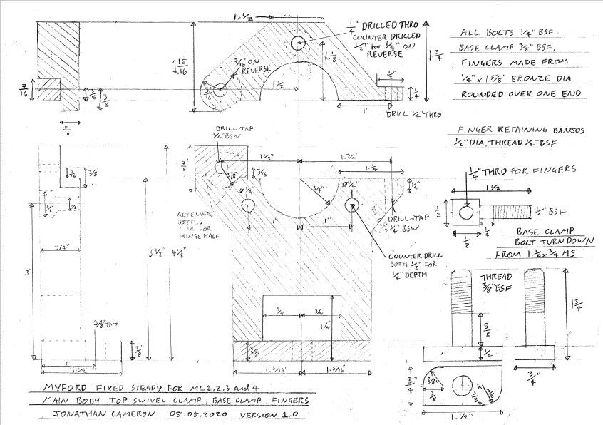
                                    Luke you'll be pleased to hear that I have just finished the drawings tonight for the fixed steady. So will take into work tomorrow and scan them before posting. There is an error on the hinge, but follow guidance of the dotted line and you'll not go far wrong. These have taken the best part of 8hours to draw up so I wasn't going to start again, just point out the error of my ways. The hardest part was trying to fit all the drawings onto a single A4 sheet, without missing any information/measurement, Plus it had to be legible.

                                    #469477
                                    Michael Gilligan
                                    Participant
                                      @michaelgilligan61133
                                      Posted by Jon Cameron on 06/05/2020 01:08:45:

                                      Now then Michael, that's intruging indeed!!! I'd seen that publishing once already but hadn't paid attention to the myford part number. What year was that sales magazine published???

                                      […]

                                      .

                                      Sorry, no idea of the publication date … ‘though it must, presumably, have been at the time when all four models were available.

                                      MichaelG.

                                      .

                                      P.S. ___ This includes a better inage of the front-cover graphic: **LINK**

                                      https://www.worthpoint.com/worthopedia/vintage-myford-lathes-instruction-501450427

                                      “Our Products cover the World” … that’s a Marketing gem star

                                      #469479
                                      Michael Gilligan
                                      Participant
                                        @michaelgilligan61133

                                        Here’s a useful reference image, adapted from : http://www.lathes.co.uk/myford-ml2-ml4/page3.html

                                        http://www.lathes.co.uk/myford-ml2-ml4/page3.html

                                        6bf2caf4-f378-4b2e-9275-6fa94d8013d9.jpeg

                                        I think that’s all I can do to help.

                                        MichaelG.

                                        #469505
                                        Brian Wood
                                        Participant
                                          @brianwood45127

                                          Nice one Michael, and yes it is just as I remember from all those years ago.

                                          Capacity was abysmal, I think it could just about manage 3/4 inch diameter!!

                                          Kind regards Brian

                                          #469514
                                          Jon Cameron
                                          Participant
                                            @joncameron26580

                                            Hello,

                                            Well i've no idea how to load a PDF to the forum. So here's a snip of the PDF from my screen instead. Feel free to PM me with your email and ill happily send the PDF to you. The steady can be built up using 20x100mm Mild Steel flat, and 10mm Mild steel flat, 6mm and 12mm round stock. The threads can also be changed within reason to suit yourself. Its drawn in imperial as that's what bolts most old myfords use so made sense. The critical dimensions are the centre height and bore. all others can be played with easily. It can also be adapted for the 3.1/8" centre height lathes by simply reducing the centre height and then work dimensions from around the bore. The main lower body can be welded or even bolted together.

                                            Please note the dotted line on the lower hinge part needs to be followed. I'm afraid I wasn't going to start again, If anyone notices any other issues with the drawing let me know. If there's a few ill redraw it. It dawned on me that not only would it not close if built as drawn it wouldn't even go together. Also should have written on the drawing to check clamp bolt for length from job, but you already knew that.

                                            Luke I hope this is of great help to you. Ill Look at the travelling steady next week.

                                            myford fixed steady drawing image.jpg

                                            #469535
                                            Michael Gilligan
                                            Participant
                                              @michaelgilligan61133
                                              Posted by Jon Cameron on 06/05/2020 09:51:51:

                                              Hello,

                                              Well i've no idea how to load a PDF to the forum. So here's a snip of the PDF from my screen instead. Feel free to PM me with your email and ill happily send the PDF to you. […]

                                              .

                                              I will certainly do that, Jon … it looks a nice adaptable design

                                              I’m also happy to convert your PDF to JPG and re-post it here, if that’s O.K.

                                              MichaelG.

                                              #469537
                                              Luke Mitchell
                                              Participant
                                                @lukemitchell30627

                                                Hi Jon,

                                                Many thanks for taking the time to measure and draft that blueprint. I'm sure it will be very helpful to others, as well as to myself. Whilst I'm not in a position to fabricate one at the moment (no welder, limited workshop) I'll be giving it a go whenever the lockdown is eased as I can use a friend's.

                                                If it's not too much of a hassle, I would also be interested in the travelling steady. I've noticed considerable flex in the work when turning longer stock and I feel that the addition of a travelling steady would be very useful for combating it. At present I'm simply taking much lighter cuts – but I'm sure it's added hours to my tinkering time!

                                                Re: the ways of my lathe, the gap (20mm or so, as I mentioned) is definitely rough-cast and not machined. What I find strange is that my ML4 was clearly purchased with a few "extras" (MT2 in the spindle, tumbler reverse) and so the original purchaser didn't skimp on expense. I wonder whether the machined gap, which Brian mentions, was a bespoke addition?

                                                Looking at photographs on lathes.co.uk (see here), it seems as though the gap is quite well finished but it's not obvious if it's been machined or not. Given that it has been painted, I would suspect not.

                                                I will take some photographs when I'm next out in the garage. Quite busy with work at the moment and so I've had less time to play that usual – I'm also waiting for the thrust bearing to be delivered so that I can rebuild the spindle.

                                                Cheers

                                                #469538
                                                Jon Cameron
                                                Participant
                                                  @joncameron26580

                                                  Hi Michael,

                                                  That may be clearer than the windows snipping tool I used for the image posted above.

                                                  Ive replied to your PM and email sent. It could be utilised on other lathes with a slotted gap and even on an ML7 for smaller work, though I think the base should be increased to help with ridgidity in that case. Also the clamp bolt would need lengthening to allow a good contact with under the bed. I know the Alomco milling attachment needed to have smaller clamps (by 1/4" length I think) to clear the casting under the bed.

                                                  Jon

                                                  Edited By Jon Cameron on 06/05/2020 11:17:26

                                                  #469543
                                                  Brian Wood
                                                  Participant
                                                    @brianwood45127

                                                    Hello Luke,

                                                    The standard spec for ML4 lathes included the uprated Morse taper in the headstock, it did make a big difference to the machine as a whole.

                                                    As for the machined gap, maybe like the cars of the 1950s where useful things like a heater were " extras" maybe the machined gap was one of those. I have no idea of course of what Dad specified in the order, but if you had a mind to carry it out, running an end mill up the gap to finish it off to some size or other would not be too difficult for someone with a suitable size of vertical mill.

                                                    You can cobble a travelling steady together to support slender work, the manufacturers version was really awful and fully equipped to tear up the surface of whatever it was supporting!

                                                    Kind regards Brian

                                                    Edited By Brian Wood on 06/05/2020 11:30:39

                                                    #469555
                                                    Jon Cameron
                                                    Participant
                                                      @joncameron26580

                                                      Hi Brian's correct on the morse taper in the spindle. The earlier ones utilised MT1 tapers, and the 7/8" 9TPI nose thread. This went into production as a standard item, the tumble reverse was an optional extra, as was the uprated tailstock, which looks more like the M-type tailstock. A thread dial indicator and also conical bronze dials were amongst the options available. As well as the accessories detailed in Michaels link above.

                                                      The travelling steady used just a solid piece of steel screwed on the side, again pretty useless for a good surface finish, and I think a ball bearing arrangement below and to the rear axis of the lathe on the support finger would be helpful to eliminate the steady messing up the finish of the workpiece

                                                      Regards

                                                      Jon

                                                      Edited By Jon Cameron on 06/05/2020 12:06:34

                                                    Viewing 25 posts - 51 through 75 (of 123 total)
                                                    • Please log in to reply to this topic. Registering is free and easy using the links on the menu at the top of this page.

                                                    Advert

                                                    Latest Replies

                                                    Home Forums Manual machine tools Topics

                                                    Viewing 25 topics - 1 through 25 (of 25 total)
                                                    Viewing 25 topics - 1 through 25 (of 25 total)

                                                    View full reply list.

                                                    Advert

                                                    Newsletter Sign-up